WAGO MOVILINK SPEEDWAY 767 User manual

Pos:2/Dokumentationallgemein/Einband/EinbandHandbuch- F ro nts ei t e 2015 - mit DocV ari abl e n (Sta nd ar d)@ 9\mod_1285229289866_0.docx@ 64941 @ @ 1
WAGO-SPEEDWAY 767
Manual
767-5204
MOVILINK® Interface (RS-232, RS-
485)
2 interfaces (2 x M12) + 4 digital inputs/outputs (2 x
M12, two inputs/outputs per connector)
Version 1.1.0
Pos: 3 / All e S eri e n ( All ge mei n e M od ul e) /Hi nw eis e z ur Dok um ent ati o n/I mpr es su m für St a ndar dh an d büc her - allg . Anga ben, Ansc hrifte n, Telef onnu mmern un d E-Mail-A dr es se n @ 3\mod_1219151118203_21.docx@ 21060 @ @ 1

2 WAGO-SPEEDWAY 767
767-5204 MOVILINK® Interface (RS-232, RS-485)
Manual
Version 1.1.0
© 2016 by WAGO Kontakttechnik GmbH & Co. KG
All rights reserved.
WAGO Kontakttechnik GmbH & Co. KG
Hansastraße 27
D-32423 Minden
Phone: +49 (0) 571/8 87 – 0
Fax: +49 (0) 571/8 87 – 1 69
E-Mail: [email protected]om
Web: http://www.wago.com
Technical Support
Phone: +49 (0) 571/8 87 – 5 55
Fax: +49 (0) 571/8 87 – 85 55
E-Mail: [email protected]om
Every conceivable measure has been taken to ensure the accuracy and
completeness of this documentation. However, as errors can never be fully
excluded, we always appreciate any information or suggestions for improving the
documentation.
E-Mail: documentation@wago.com
We wish to point out that the software and hardware terms as well as the
trademarks of companies used and/or mentioned in the present manual are
generally protected by trademark or patent.
=== Ende d er Lis t e f ür Te xt mar ke Ei nb and _ vor n e = = =

WAGO-SPEEDWAY 767 Table of Contents 3
767-5204 MOVILINK® Interface (RS-232, RS-485)
Manual
Version 1.1.0
Pos: 5 /D o ku ment ati on allg e mei n /Ver zei c hni ss e/I nh alt s verz ei ch nis - Ü ber schrif t oG und Ver zei c h nis @ 3\mod_1219151230875_21.docx@ 21063@ @ 1
Table of Contents
1Notes about this Documentation................................................................. 6
1.1 Validity of these Operating Instructions ................................................... 6
1.2 Copyright................................................................................................... 6
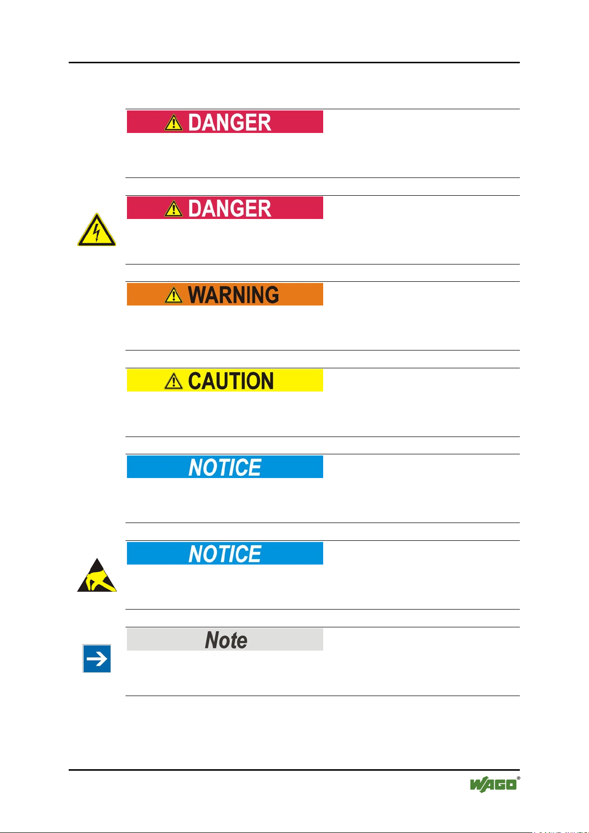
1.3 Symbols..................................................................................................... 7
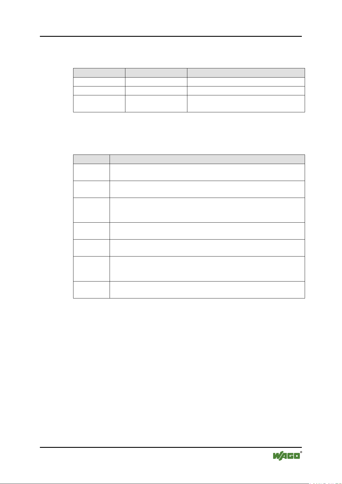
1.4 Number Notation....................................................................................... 9
1.5 Font Conventions ...................................................................................... 9
2Important Notes ......................................................................................... 10
2.1 Legal Bases ............................................................................................. 10
2.1.1 Subject to Changes ............................................................................. 10
2.1.2 Personnel Qualification ...................................................................... 10
2.1.3 Intended Use....................................................................................... 11
2.1.4 Technical Condition of Specified Devices ......................................... 11
2.2 Safety Advice (Precautions).................................................................... 12
2.3 Safety Equipment .................................................................................... 13
2.4 Notes on Operation ................................................................................. 14
3Device Description ..................................................................................... 15
3.1 Connectors............................................................................................... 17
3.2 Marking Possibilities and Fastening ....................................................... 18
3.3 Display Elements .................................................................................... 19
3.4 Labeling................................................................................................... 20
3.5 Schematic Diagram ................................................................................. 22
3.6 Dimensions.............................................................................................. 23
3.7 Technical Data ........................................................................................ 24
3.7.1 Device Data ........................................................................................ 24
3.7.2 Supply................................................................................................. 24
3.7.3 Communication .................................................................................. 24
3.7.4 MOVILINK®Interfaces ..................................................................... 25
3.7.5 Digital Inputs ...................................................................................... 25
3.7.6 Input Characteristic ............................................................................ 25
3.7.7 Digital Outputs ................................................................................... 26
3.7.8 Information for Actuator Selection .................................................... 26
3.7.9 Effect of Operating State on Outputs ................................................. 27
3.7.10 Configurable Functions of the MOVILINK®Interfaces .................... 27
3.7.11 Configurable Functions of the Digital Inputs/Outputs ....................... 27
3.7.12 Diagnostics ......................................................................................... 27
3.7.13 Process Image..................................................................................... 28
3.7.14 Indicators ............................................................................................ 28
3.7.15 Isolation .............................................................................................. 28
3.8 Approvals ................................................................................................ 29
3.9 Standards and Guidelines........................................................................ 30
4Mounting..................................................................................................... 31
4.1 Information on Mounting........................................................................ 31
4.2 Tools and Accessories Required for Mounting....................................... 33
4.3 Direct Mounting on Your System ........................................................... 34
4.4 Mounting on a Carrier Rail (only with WAGO Accessories)................. 35

4 Table of Contents WAGO-SPEEDWAY 767
767-5204 MOVILINK® Interface (RS-232, RS-485)
Manual
Version 1.1.0
4.4.1 Fastening the Carrier Rail Adapter to the Module ............................. 35
4.4.2 Fastening the Module with Carrier Rail
Adapter to a Carrier Rail .................................................................... 36
4.5 Mounting on a Profile Rail (only with WAGO Accessories) ................. 37
4.5.1 Fastening the Profile Adapter to the Module ..................................... 37
4.5.2 Fastening the Module with Profile
Adapter to a Profile Rail..................................................................... 38
4.6 Marking and Replacing the Marking Spaces .......................................... 39
4.7 Mounting the Spacer in the Case of Compact Arrangement................... 40
5Connecting Data and Supply Cables........................................................ 42
5.1 Notes ....................................................................................................... 42
5.2 Required Accessories .............................................................................. 43
5.3 Connecting the S-BUS Cables ................................................................ 44
5.4 Connecting the Supply Cable.................................................................. 46
5.5 Connecting Interface Cables ................................................................... 48
5.5.1 Connection Example .......................................................................... 50
5.6 Connecting Sensor/Actuator Cables ....................................................... 51
6Commissioning ........................................................................................... 53
7Parameterizing ........................................................................................... 54
7.1 Electronic Type Label ............................................................................. 56
7.2 Diagnostic Overview............................................................................... 57
7.3 Input and Output Parameters................................................................... 59
7.3.1 Connection Mode "Digital Output".................................................... 60
7.3.2 Connection Mode "Digital Input" ...................................................... 62
7.4 Parameters of the Interfaces .................................................................... 63
7.4.1 Operating Mode.................................................................................. 63
7.4.2 Parameters of the serial Interfaces...................................................... 63
7.4.3 Parameters of the MOVILINK®Interfaces ........................................ 63
7.5 Global Settings ........................................................................................ 64
7.6 Parameters of Field Supply ..................................................................... 64
7.7 Automatic Storage of System Parameters............................................... 65
7.8 Updating the Firmware ........................................................................... 65
8Process Image ............................................................................................. 66
8.1 Process Image in Easy Mode .................................................................. 67
8.1.1 Input Data in Easy Mode .................................................................... 67
8.1.2 Output Data in Easy Mode ................................................................. 70
8.2 Process Image in Mailbox 2.0 Mode....................................................... 73
8.2.1 Input Data in Mailbox 2.0 Mode ........................................................ 73
8.2.2 Output Data in Mailbox 2.0 Mode ..................................................... 75
9MOVILINK®Interfaces............................................................................ 77
9.1 Function Block Simatic S7...................................................................... 77
9.2 Data Transfer........................................................................................... 77
9.2.1 Data Transfer in Easy Mode............................................................... 77
9.2.2 Data Transfer in Mailbox Mode ......................................................... 84
9.2.2.1 MOVILINK®Mailbox 2.0 Message Types................................... 84
9.2.2.1.1 Message Type 6 ........................................................................ 85
9.2.2.1.2 Message Type 8 ........................................................................ 86

WAGO-SPEEDWAY 767 Table of Contents 5
767-5204 MOVILINK® Interface (RS-232, RS-485)
Manual
Version 1.1.0
9.2.2.1.3 Message Type 9 ........................................................................ 88
9.2.2.1.4 Using Message Type 6.............................................................. 89
9.2.2.1.5 Using Message Type 8 in Mailbox Mode................................. 93
10 Diagnostics .................................................................................................. 99
10.1 LED Signaling......................................................................................... 99
11 Service ....................................................................................................... 102
11.1 Updating the Firmware ......................................................................... 102
11.2 Replacing the Module ........................................................................... 102
11.2.1 Disconnecting the Cables ................................................................. 102
11.2.2 Removing the Module from Your System ....................................... 103
11.2.3 Removing the Module from the Carrier Rail ................................... 103
11.2.4 Removing the Module from the Profile Adapter.............................. 104
11.2.5 Connecting the Module .................................................................... 104
11.3 Disposal................................................................................................. 104
12 Appendix................................................................................................... 105
12.1 Diagnostic Information ......................................................................... 105
12.2 Mailbox 2.0 Transmission Method ....................................................... 106
12.2.1 Message ............................................................................................ 106
12.2.2 Transmission Channel ...................................................................... 107
12.2.2.1 The Handshake Byte.................................................................... 108
12.2.3 Communication Phases .................................................................... 109
12.2.3.1 Synchronization ........................................................................... 109
12.2.3.1.1 Mailbox Commands................................................................ 109
12.2.3.1.2 Acknowledgement .................................................................. 110
12.2.3.1.3 Signaling ................................................................................. 110
12.2.3.1.4 Finite Automation ................................................................... 111
12.2.3.2 Data Exchange ............................................................................. 112
12.2.3.2.1 Example .................................................................................. 113
List of Figures .................................................................................................... 114
List of Tables...................................................................................................... 115
=== En de der Lis te für T extmar ke Verz eich nis_vor ne == =

6 Notes about this Documentation WAGO-SPEEDWAY 767
767-5204 MOVILINK® Interface (RS-232, RS-485)
Manual
Version 1.1.0
Pos: 7 /A lle Ser ie n (Al lg em ein e M od ul e)/Ü ber sc hri ft en f ür all e S erie n/H i nweis e zur D o ku ment ati on /Hi nw eise zu dies er D o kum ent atio n - Ü b ers chr if t 1 @ 4\mod_1237987661750_21.docx@ 29029 @ 1@ 1
1 Notes about this Documentation
Pos: 8 /Ser i e 76 7 (WA GO-SP EED WAY) /H in weis e zur D ok um en tati o n/Hi nw eis e z ur Do kum e ntat io n I/ O-M odul e 7 6 7-xxxx @ 5\mod_1248172015859_21.docx@ 38666@ @ 1
The module shall only be installed and operated in conjunction with these
operating instructions and the system description.
Pos: 9 /Ser i e 76 7 (WA GO-SP EED W AY) /Wic hti ge Erl äu ter ung en/ Sic her hei ts hi nweis e/ War n ung /War nu ng : R ele as e N ot es be ac ht en @ 8\mod_1278912368761_21.docx@ 59530@ @ 1
Observe release notes!
Please note that, within the SPEEDWAY system, a function is provided without
restriction only if all system's components have the same system-wide firmware
release. Therefore, always observe the appropriate release notes on products used.
Pos: 10 /S er ie 76 7 ( WA GO -S PE ED W AY) / Wic hti g e E rl ä ut eru ng e n/ Sic her h eit s hin w eis e/ A ch tu ng / Ach tu ng : V ers or g u ngs a usl eg ung @ 8\mod_1278912433448_21.docx@ 59533@ @ 1
Supply layout!
In addition to these operating instructions, you will need the “WAGO
SPEEDWAY 767, System Description and Information” manual, which can be
downloaded at www.wago.com. There you will find information regarding supply
layout, etc.
Pos:11/Alle Serien(AllgemeineModule)/Hinweise zurDokumentation/Hinweise/Hinweis:Dokumentationaufbewahren@ 4\mod_1237987339812_21.docx@ 29026@ @ 1
Always retain this documentation!
This documentation is part of the product. Therefore, retain the documentation
during the entire service life of the product. Pass on the documentation to any
subsequent user. In addition, ensure that any supplement to this documentation is
included, if necessary.
Pos: 12 /S er ie 76 7 ( WA GO -SPEEDWAY)/Hinweisez urDokumentation/Gültigkeit DokumentationI/O-Modul 767-xxxx@ 5\mod_1248172494859_21.docx@ 38679@ 2 @ 1
1.1 Validity of these Operating Instructions
These operating instructions are only applicable to the WAGO SPEEDWAY 767
Series module MOVILINK® Interface (RS-232, RS-485), 767-5204.
Pos: 13.1 /All e Seri en ( Al lg emei ne M o dul e)/H i nweis e zur D o ku ment ati on /Ur heb ersc hutz ausführlich @ 4\mod_1235565145234_21.docx @ 27691@ 2@ 1
1.2 Copyright
This Manual, including all figures and illustrations, is copyright-protected. Any
further use of this Manual by third parties that violate pertinent copyright
provisions is prohibited. Reproduction, translation, electronic and phototechnical
filing/archiving (e.g., photocopying) as well as any amendments require the
written consent of WAGO Kontakttechnik GmbH & Co. KG, Minden, Germany.
Non-observance will involve the right to assert damage claims.
Pos:13.2/Dokumentationallgemein/Gliederungselemente/---Seite nwe chs el--- @ 3\mod_1221108045078_0.docx @ 21810@ @ 1

WAGO-SPEEDWAY 767 Notes about this Documentation 7
767-5204 MOVILINK® Interface (RS-232, RS-485)
Manual
Version 1.1.0
Pos: 13.3 /All e Seri en ( Al lg emei ne M o dul e)/Ü ber sc hri fte n f ür all e S eri en/ Hin wei s e z ur D ok um enta ti on/ S ymbol e - Ü ber sc hr ift2 @ 13\mod_1351068042408_21.docx@ 105270@ 2 @ 1
1.3 Symbols
Pos: 13 .4.1 /Al le Seri en (All gemei ne Mod ule)/ Wichti ge Erl äuter unge n/Sich erheit s- undsonstigeHinweise/Gefahr/Gefahr:_WarnungvorPersonenschädenallgemein_- Er l äu ter ung @ 13 \mod_1343309450020_21. docx @ 10 1029 @ @ 1
Personal Injury!
Indicates a high-risk, imminently hazardous situation which, if not avoided, will
result in death or serious injury.
Pos: 13 .4.2 /Al le Seri en (All gemei ne Mod ule)/ Wichti ge Erl äuter unge n/Sich erheit s- und so ns ti ge H in wei s e/ Gef ahr /G ef ahr : _War nu ng vor P er so nen sc hä de n dur c h el ek tri sc he n St ro m_ - Erläuterung@ 13\mod_1343309694914_21.docx@ 101030@ @ 1
Personal Injury Caused by Electric Current!
Indicates a high-risk, imminently hazardous situation which, if not avoided, will
result in death or serious injury.
Pos: 13 .4.3 /Al le Seri en (All gemei ne Mod ule)/ Wichti ge Erl äuter unge n/Sich erheit s- und s ons ti g e Hi n wei s e/W ar nung / War n ung: _W arn u ng vor P er so nens c häd e n al lg em ei n_ - Erläuterung @ 13\mod_1343309877041_21.docx@ 101035@ @ 1
Personal Injury!
Indicates a moderate-risk, potentially hazardous situation which, if not avoided,
could result in death or serious injury.
Pos: 13 .4.4 /Al le Seri en (All gemei ne Mod ule)/ Wichti ge Erl äuter unge n/Sich erheit s- undsonstige Hin weise/Vor sic ht /V or si ch t: _ War nu ng vor P er s one nsc hä de n al lg e mei n_ - Erläuterung@ 13\mod_1343310028762_21.docx@ 101038@ @ 1
Personal Injury!
Indicates a low-risk, potentially hazardous situation which, if not avoided, may
result in minor or moderate injury.
Pos: 13 .4.5 /Al le Seri en (All gemei ne Mod ule)/ Wichti ge Erl äuter unge n/Sich erheit s- undsonstigeHinweise/Achtung/Achtung:_Warnung vor S ac hs c häd en al lg e mei n_ - Erläuterung@ 13\mod_1343310134623_21.docx@ 101041 @ @ 1
Damage to Property!
Indicates a potentially hazardous situation which, if not avoided, may result in
damage to property.
Pos: 13 .4.6 /Al le Seri en (All gemei ne Mod ule)/ Wichti ge Erl äuter unge n/Sich erheit s- und so ns ti ge H in wei s e/ Ach tu ng/ Ach tu ng : _ War nu ng vor S ac hsc hä d en d ur c h el ektr os tat is ch e Aufladung_- Erläuterung @ 13\mod_1343310227702_21.docx@ 101044@ @ 1
Damage to Property Caused by Electrostatic Discharge (ESD)!
Indicates a potentially hazardous situation which, if not avoided, may result in
damage to property.
Pos: 13 .4.7 /Al le Seri en (All g e mei ne M o d ule) / Wic hti ge Erl äut er u ng en/ S ich er h eits - und sons tigeHin weise/Hinweis/Hinweis:_ WichtigerHi nweis allgemein_ - Erläuterung@ 13\mod_1343310326906_21.docx@ 101047@ @ 1
Important Note!
Indicates a potential malfunction which, if not avoided, however, will not result in
damage to property.
Pos: 13 .4.8 /Al le Seri en (All gemei ne Mod ule)/ Wichti ge Erl äuter unge n/Sich erheit s- und so ns t ig e Hi n wei s e/I nf or mat io n/I nf or mat io n: _W eiter e I nf or ma ti on allg e mei n_ - Erl äu ter ung @ 13 \mod_1343310439814_21.docx@ 101051@ @ 1

8 Notes about this Documentation WAGO-SPEEDWAY 767
767-5204 MOVILINK® Interface (RS-232, RS-485)
Manual
Version 1.1.0
Additional Information:
Refers to additional information which is not an integral part of this
documentation (e.g., the Internet).
Pos:13.5/Dokumentationallgemein/Gliederungselemente/---Seite nwe chs el--- @ 3\mod_1221108045078_0.docx @ 21810 @ @ 1

WAGO-SPEEDWAY 767 Notes about this Documentation 9
767-5204 MOVILINK® Interface (RS-232, RS-485)
Manual
Version 1.1.0
Pos: 13.6 /All e Seri en ( Al lg emei ne M o dul e)/H i nweis e zur D o ku ment ati on /Dar s tell ung der Za hle nsys te me - Ü b ers chr if t 2 un d I n hal t @ 3\mod_1221059454015_21.docx@ 21711 @ 2 @ 1
1.4 Number Notation
Table 1: Number Notation
Number Code
Example
Note
Decimal
100
Normal notation
Hexadecimal
0x64
C notation
Binary
'100'
'0110.0100'
In quotation marks, nibble separated with
dots (.)
Pos: 13.7 /All e Seri en ( Al lg emei ne M o dul e)/H i nweis e zur D o ku ment ati on /Sc hri ft kon venti o ne n - Ü bers c hri ft 2 undInhalt@ 3\mod_1221059521437_21.docx@ 21714@ 2 @ 1
1.5 Font Conventions
Table 2: Font Conventions
Font Type
Indicates
italic
Names of paths and data files are marked in italic-type.
e.g.: C:\Program Files\WAGO Software
Menu
Menu items are marked in bold letters.
e.g.: Save
>
A greater-than sign between two names means the selection of a
menu item from a menu.
e.g.: File > New
Input
Designation of input or optional fields are marked in bold letters,
e.g.: Start of measurement range
“Value”
Input or selective values are marked in inverted commas.
e.g.: Enter the value “4 mA” under Start of measurement range.
[Button]
Pushbuttons in dialog boxes are marked with bold letters in square
brackets.
e.g.: [Input]
[Key]
Keys are marked with bold letters in square brackets.
e.g.: [F5]
Pos: 14 /D o ku me nt ati o n al lg e mei n/ Gl ie der ung s ele m e nte /---Seit e n we chs el --- @ 3\mod_1221108045078_0.docx@ 21810 @ @ 1

10 Important Notes WAGO-SPEEDWAY 767
767-5204 MOVILINK® Interface (RS-232, RS-485)
Manual
Version 1.1.0
Pos: 15 /A lle Ser ien (Al lge meine Mo dule)/ Über schrif ten für all e Serie n/Wic htig e Erläuterungen/WichtigeErläuterungen- Über sc hr ift 1 @ 4\mod_1241428899156_21.docx@ 32170@ 1 @ 1
2 Important Notes
Pos: 16 .1 /All e Seri en( Allg emeine M odul e)/Wic htig e Erläut erung en/ Wichtig e Erlä uteru ngen - Einl ei t ung @ 3\mod_1221059818031_21.docx@21717 @ @ 1
This section includes an overall summary of the most important safety
requirements and notes that are mentioned in each individual section. To protect
your health and prevent damage to devices as well, it is imperative to read and
carefully follow the safety guidelines.
Pos: 16.2 /All e Seri en ( Al lg emei ne M o dul e)/Ü ber sc hri fte n f ür all e S eri en/ Wi cht ig e Er lä uter u ngen /Re ch tli ch e Gr u ndl age n - Ü ber sc hri ft 2 @ 3\mod_1221060626343_21.docx@ 21726@ 2 @ 1
2.1 Legal Bases
Pos: 16.3 /All e Seri en ( Al lg emei ne M o dul e)/ Wi c hti ge Erl äut er u ng e n/ Änd er u ng s vor be hal t - Ü bersc hrift 3 un dI nhalt @ 3\mod_1221060036484_21.docx@ 21720@ 3 @ 1
2.1.1 Subject to Changes
WAGO Kontakttechnik GmbH & Co. KG reserves the right to provide for any
alterations or modifications that serve to increase the efficiency of technical
progress. WAGO Kontakttechnik GmbH & Co. KG owns all rights arising from
the granting of patents or from the legal protection of utility patents. Third-party
products are always mentioned without any reference to patent rights. Thus, the
existence of such rights cannot be excluded.
Pos:16.4/Serie767(WAGO-SPE ED WA Y) / Wi c hti g e Er l ä ut er ung e n/I /O-M od ul / Per s on alq u ali fi ka tio n 767-xxxx @ 5\mod_1248175871265_21.docx@ 38705@ 3 @ 1
2.1.2 Personnel Qualification
All sequences implemented on the module may only be carried out by electrical
specialists with sufficient knowledge in automation. The specialists must be
familiar with the current standards and guidelines for the module and automation
environment.
Pos:16.5/Dokumentationallgemein/ Gl ie der ung s ele m en te /---Sei t en we chs el --- @ 3\mod_1221108045078_0.docx@ 21810 @ @ 1

WAGO-SPEEDWAY 767 Important Notes 11
767-5204 MOVILINK® Interface (RS-232, RS-485)
Manual
Version 1.1.0
Pos:16.6/Serie767(WAGO-SPE ED WA Y) / Wi c hti g e Er l ä ut er ung e n/I /O-M odul / Bes tim m u ng sg e mäß e Verw e nd ung 767-5204@ 14\mod_1357822229320_21.docx@ 108238@ 3 @ 1
2.1.3 Intended Use
The 767-5204 module has two serial interfaces for controlling drives using the
MOVILINK®protocol and configurable digital inputs and outputs. These are
suitable for the output of digital signals as well as for detecting digital field
signals.
The module is supported by all series 767 fieldbus couplers of Release 5 or
higher.
Pos:16.7/Serie767(WAGO-SPE ED WA Y) / Wi c hti g e Er l ä ut er ung e n/I /O-M odul / Bes tim m u ng sg e mäß e Verw e nd ung 767-I O s allg e mei n 1 @ 7\mod_1266322273828_21.docx@50731 @ @ 1
The module may not be used to control safety-related functions, i.e. it cannot be a
functional part of a safety function.
Pos:16.8/Serie767(WAGO-SPE ED WA Y) / Wi c hti g e Er l ä ut er ung e n/I /O-M odul / Bes tim m u ng sg e mäß e Verw e nd ung 767-I O s allg e mei n 2 @ 5\mod_1248176511796_21.docx@38751 @ @ 1
The module may only be operated in combination with components of the WAGO
SPEEDWAY 767 Series.
The module was developed for applications requiring IP 67 (NEMA type 6, 6P)
protection.
Pos:16.9/Serie767(WAGO-SPE ED WA Y) / Wi c hti g e Er l ä ut er ungen/I/O-Mod ul/ B es ti mm u ng sg e mäß e Ver we nd ung 7 67-xxxx allg emein3 @ 8\mod_1278997190572_21.docx@ 59680@ @1
Applications other than those described in this manual are not permitted.
Pos: 16.1 0 / All e Seri e n ( Al lg e m ein e M o dul e) / Wi ch tig e Erlä ut er u ng en/ T ech ni sc her Zus ta nd der Gerät e - Ü bers chrift 3 un dI nhalt @ 3\mod_1221060446109_21.docx @ 21723@ 3@ 1
2.1.4 Technical Condition of Specified Devices
The devices to be supplied ex works are equipped with hardware and software
configurations, which meet the individual application requirements. WAGO
Kontakttechnik GmbH & Co. KG will be exempted from any liability in case of
changes in hardware or software as well as to non-compliant usage of devices.
Please send your request for modified and new hardware or software
configurations directly to WAGO Kontakttechnik GmbH & Co. KG.
Pos: 16.1 1 /D o ku ment ati o n all ge mei n/G li ed eru ngsel e me nte/---S ei ten w ec hs el--- @ 3 \mod_1221108045078_0.docx@ 21810@ @ 1

12 Important Notes WAGO-SPEEDWAY 767
767-5204 MOVILINK® Interface (RS-232, RS-485)
Manual
Version 1.1.0
Pos: 16.1 2 / All e Seri e n ( Al lg e m ein e M o dul e) /Ü b ers c hri ft en für all e Ser i en/ Wi c hti g e Er l äut er ung e n/ Sic her hei t shi n wei s e - Ü b ers chr if t 2 @ 6\mod_1260180299987_21.docx@ 46724 @ 2@ 1
2.2 Safety Advice (Precautions)
Pos: 16.1 3 / S eri e 767 ( W AG O-S PE ED WA Y) / Wic ht ig e Erläu ter ung en /Sic h erh ei ts hin w eis e /G ef ahr/ G ef ahr : El ektr is c he S pa n nu ng @ 8\ mod_1278307980373_21.docx@ 58901@ @ 1
Electric voltage!
Operate the 767 Series components exclusively with 24 VDC PELV (Protective
Extra Low Voltage) or SELV (Safety Extra Low Voltage) voltage sources. Failure
to comply may result in electric shock.
Pos: 16.1 4 / S eri e 767 ( W AG O-S PE ED WAY )/ Wi ch ti g e Erläu ter ung en /Sic h erh ei ts hi n wei se / V ors ic h t/ Vor si c ht: Heiß e Ansc hl uss b uch se n @ 8\mod_1278308217203_21.docx @ 58913@ @ 1
Hot connection sockets!
Even when taking into account derating, high surface temperatures on the metallic
connection sockets and on the enclosure can arise during operation. If the 767
Series component has been in operation, allow it to cool off before moving it.
Pos: 16.1 5 / S eri e 767 ( W AG O-S PE ED WA Y)/ Wic ht ig e Er läu ter ung en /Si c her h eits hi nw eis e/A c htu ng /Ac ht ung : H öc hs te S tr o mbel as tbar kei t der V ers or g ungs k ont ak te @ 8\mod_1278308653219_21.docx@ 58916 @ @ 1
The highest current carrying capacity of the supply contacts is 4 A!
Always observe the maximum current carrying capacity per supply line (ULS, UA)
for each 767 Series component and the overall power consumption for all
767 components. Neither of these values shall exceed 4 A since an increase in
current causes the contacts to overheat and damages the 767 Series components.
Information regarding the power demand of each 767 Series component can be
found in the corresponding data sheet, which is available from www.wago.com.
Pos: 16.1 6 / S eri e 767 ( W AG O-S PE ED WAY )/ Wi ch ti g e Erläu ter ung en /Sic h erh ei ts hi n wei se / Ac ht u ng /Ac ht ung : Off en e Ansc hl üss e @ 8\mod_1278308159953_21.docx@58910 @ @ 1
Exposed connections!
If connections have not been closed with protective caps, liquid or dirt can
penetrate the components of the 767 Series module and ruin it. Therefore, close
all unnecessary connections with protective caps, which must be ordered
separately, in order to maintain the IP67 degree of protection. (See section
“Accessories” of the fieldbus coupler/controller manual.)
Pos: 16.1 7 / S eri e 767 ( W AG O-S PE ED WA Y)/ Wi ch ti ge Erl äu ter ung en /I/ O-M odul / Sic her hei tshi n wei se 767-xxxx_2 @ 7\mod_1267623532771_21.docx @ 51669@ @ 1
•Disconnect the power supply from the system on which you wish to mount
the 767 Series device.
•Observe the appropriate accident prevention regulations for your system
during assembly, start-up, maintenance, and repairs. For example, BGV A3,
“Electrical systems and equipment”.
•The operating instructions for the 767 Series module and the system
description must be laid out ready on site.
•Observe the exact positioning (coding) between plug and socket.
•The 767 Series device shall not come into contact with substances having
seeping and insulating properties. Otherwise, additional measures shall be

WAGO-SPEEDWAY 767 Important Notes 13
767-5204 MOVILINK® Interface (RS-232, RS-485)
Manual
Version 1.1.0
taken for the device, such as installation of an enclosure that is resistant to
the above-mentioned substance properties.
•Electronic components fulfilling the ESD requirements according to the IEC
61000-6-2 are integrated in the 767 device. As higher voltages may occur,
under unfavorable circumstances, due to electrical charge in the field,
discharge must be ensured before performing work on the 767 system.
•Ensure that the potential equalization is correctly laid out.
Pos: 16.1 8 / S eri e 767 ( W AG O-S PE ED WAY )/ Wi ch ti g e Erläu ter ung en /I/ O-M odul / Sic her hei tshi n wei se 7 67-xxxx_3 @ 7\mod_1267624103126_21.docx@ 51676@ @ 1
•Keep all cables a sufficient distance away from electromagnetic sources of
interference in order to maintain a high level of interference resistance of
the 767 system against electromagnetic emissions. Use only shielded cables
at the necessary locations, and always observe the appropriate standards for
EMC-suitable installations.
•For the power supply and for the S-BUS, use only pre-assembled WAGO
system cables, so the specified characteristics of the technical data can be
achieved.
Pos: 16.1 9 / S eri e 767 ( W AG O-S PE ED WAY )/ Wi ch ti g e Erläu ter ung en /I/ O-M odul / Sic her hei tshi n wei se 7 67-xxxx_4 @ 7\mod_1267623157545_21.docx@ 51662@ @ 1
•Replace defective or damaged modules (e.g., deformed connections), else
function disruptions can occur in the respective fieldbus stations or nodes.
•When laying any cables, make sure that you do not lay them within the
shear range of movable machine parts.
•For each activity, observe the corresponding personnel qualification in the
corresponding section.
•Observe the marking on the front and rear side of the module.
Pos: 16.2 0 / S eri e 767 ( W AG O-S PE ED WAY )/ Wi ch ti g e Erläu ter ung en /I/ O-M odul / Sic her hei tsei nr ich tu nge n 76 7-xxxx @ 7 \mod_1268142379773_21.docx@ 52055 @2 @ 1
2.3 Safety Equipment
All 767 Series products are designed to meet the requirements of IP67. This
includes complete protection against accidental contact with electrical voltage and
currents – even when wet.
Pos: 16.2 1 /D o ku ment ati o n all ge mei n/G li ed eru ngsel e ment e/ ---S eit en wec hs el--- @ 3 \mod_1221108045078_0.docx@ 21810@ @ 1

14 Important Notes WAGO-SPEEDWAY 767
767-5204 MOVILINK® Interface (RS-232, RS-485)
Manual
Version 1.1.0
Pos: 16.2 2 / S eri e 767 ( W AG O-S PE ED WAY )/ Wi ch ti g e Erläu ter ung en /I/ O-M odul / Hin wei se z um Betr i eb 7 67-xxxx, Teil 1 @ 7\mod_1266921815843_21.docx@ 51219@ 2 @ 1
2.4 Notes on Operation
When integrating the 767 module in your machine or system, all the currently
applicable norms, regulations and guidelines shall be observed during all
activities: for example, BGV A3, “Electrical systems and equipment”,
DIN EN 418, EN 60204. The emergency stop equipment shall remain effective in
all operating modes of the system and machine.
For protection from electromagnetic interferences
•Connect your system to protective earth (PE), and
Pos: 16.2 3 / S eri e 767 ( W AG O-S PE ED WAY )/ Wi ch ti g e Erläu ter ung en /I/ O-M odul / Hin weise z um Betri eb 767-I /O , T eil 2 @ 5\mod_1248180225875_21.docx@ 38755@ @ 1
•Ensure that the cable routing and the installation of the fieldbus cable, S-
BUS cable, supply cable, and sensor or actuator cable are correct.
Pos: 16.2 4 / S eri e 767 ( W AG O-S PE ED WAY )/ Wi ch ti g e Erläu ter ung en /I/ O-M odul / Hin wei se z um Betr i eb 7 67-xxxx, Teil 3 @ 7\mod_1266921848140_21.docx@ 51222@ @ 1
The following elements for 24 V supply shall be present:
•Outer lightning protection on buildings
•Inner lightning protection of supply lines and signal lines
•Safe electrical separation of low voltage 24 VDC through PELV (Protective
Extra Low Voltage) or SELV (Safety Extra Low Voltage) voltage sources
Pos: 17 /D o ku me nt ati o n al lg e mei n/ Gl ie der ung s ele m e nte /---Seit e n we chs el --- @ 3\mod_1221108045078_0.docx@ 21810 @ @ 1

WAGO-SPEEDWAY 767 Device Description 15
767-5204 MOVILINK® Interface (RS-232, RS-485)
Manual
Version 1.1.0
Pos: 18 /A lle Ser ien (Al lge meine Mo dule)/ Über schrif ten für all e Serie n/Ger äteb eschr eibung /Ger ätebe schrei bung - Ü ber sc hr ift 1 @ 3\mod_1233756084656_21.docx@ 27096@ 1 @ 1
3 Device Description
Pos:19.1/Serie767(W AGO-SP E ED WA Y) / Ger ät eb esc hr ei bu ng/ I /O-M o dul e/ G er ät e bes chr eib ung 7 67-5204@ 14\mod_1357822310944_21.docx@ 108246@ @ 1
The 767-5204 module makes it possible to connect drives that support the
MOVILINK®protocol to an RS-232 or RS-485 interface. In addition, two of the
connections can each be parameterized with two signal channels as digital inputs
or outputs. In this way, the module has space to connect up to four digital
actuators or sensors to both control solenoid valves, contactors, etc., and to
evaluate sensors, proximity switches, etc.
The properties (e.g. filter times) of all signal channels of the module can be
parameterized independently, depending on fieldbus via the device description file
(e.g. GSD, GSDML, etc.) of a fieldbus or independent of the fieldbus via an
FDT/DTM frame application such as WAGOframe.
The module supports the MOVILINK®protocol from SEW-EURODRIVE GmbH
& Co.KG. Support is limited to a subset of the protocol. Supported are PDU types
0x05 (cyclic) and 0x85 (acyclic) that send a telegram with 6 bytes of user data to
the drive.
Data can be transferred in "Mailbox" or "Easy" mode.
In Mailbox mode, communication with the module is message-based, i.e. a set of
MOVILINK®user data is transferred to the mailbox as a block and then
transferred to the module. Received data also arrives at the control unit as a block.
In Mailbox mode, both MOVILINK®interfaces are accessed simultaneously.
In Easy mode, the MOVILINK® data is written from the control unit to the
process image and read from the process image directly. Only one serial interface
can be used and only PDU type 0x05 (cyclic) is supported.
All data from the drive is transferred transparently to the connected fieldbus
master. The module works independent of the fieldbus used half-duplex at up to
57600 baud depending on the configuration.
The default operating mode of the serial interfaces is RS-485 half-duplex. The
default data transmission rate is 9600 baud. 1 start bit, 8 data bits and 1 stop bit
are sent. There is even parity generation and dataflow control.
As required, the module can be reconfigured in wide ranges:
•Module operating mode: Mailbox mode or Easy mode (either interface 1 or
2)
•Operating mode of the serial interfaces: RS-232 or RS-485
•Baud rate of the serial interfaces: 9600 baud or 57600 baud
In RS-232 mode, the interface works in accordance with the TIA/EIA-232-F and
CCITT V 28/DIN 66259-1 standards. In RS-485 mode, the interface works in
accordance with the TIA/EIA-485-A, DIN 66259 standards.

16 Device Description WAGO-SPEEDWAY 767
767-5204 MOVILINK® Interface (RS-232, RS-485)
Manual
Version 1.1.0
The positive switching digital inputs have a characteristic in accordance with
IEC61131-2, Type 2. They have extensive parameterization options channel-by-
channel such as filter times or signal inversion.
The positive switching outputs are designed for 0.5 A (max. 0.6 A) and short
circuit/overload protected. There are also parameterization options for the outputs
channel-by-channel such as substitute value strategy.
Pos:19.2/Dokumentationallgemein/Gliederungselemente/---Seite nwe chs el--- @ 3\mod_1221108045078_0.docx @ 21810 @ @ 1

WAGO-SPEEDWAY 767 Device Description 17
767-5204 MOVILINK® Interface (RS-232, RS-485)
Manual
Version 1.1.0
Pos: 19.3 /All e Seri en ( Al lg emei ne Mo d ule) /Ü bers c hri ft en f ür all e S eri e n/G erä te bes c hrei bu ng /A nsc hlüs s e - Ü ber sc hr ift 2 @ 4\mod_1240984262656_21.docx@ 31961@ 2 @ 1
3.1 Connectors
Pos:19.4/Serie767(WAGO-SPE ED WA Y) / Ger ät eb esc hrei bu ng /A nsc hl üs s e/I /O-Mod ul e/A nsc hl üss e 767-52 03, -52044xM12- Bild @ 12\mod_1329737283576_21.docx@ 89297 @ @ 1
Figure 1: Connectors (exemplary)
Pos:19.5/Serie767(WAGO-SPE ED WA Y) / Ger ät eb esc hrei bu ng /A nsc hl üs s e/I /O -Mo d ule/ L eg e nd e An s chl us s 767-xxxx S-BU S @ 5\mod_1248847875187_21.docx@ 39167@ @ 1
Table 3: Legend for figure "Connectors"
Position
Description
Function
1
S-BUS input
M12 plug, B-coded
For transmitting data from previous 767
Series components.
2
S-BUS output
M12 socket, B-coded
For transmitting S-BUS data to the next
767 Series components or to the S-BUS
terminator.
Pos:19.6/Serie767( WAGO-S PE ED WA Y) / Ger ät ebes c hr ei bu ng /A ns c hl üss e/ I /O-M o dul e/ L eg end e Ansc hl uss 7 67-520 4 Seriel le Sch nittst elle @ 14 \mod_1360912437399_21.docx @ 111964@ @ 1
3
Serial interfaces 1 and 2
M12 socket, A coded
MOVILINK®devices with one of the
following interfaces are supported:
RS-232, RS-485.
Pos:19.7/Serie767(WAGO-SPE ED WA Y) / Ger ät eb esc hrei bu ng /A nsc hl üs s e/I /O -Mo d ule/ L eg e nd e An s chl us s 767-520x Digitalein-/ausg äng e @ 11\mod_1319721824565_21.docx@ 82639@ @ 1
4
Digital inputs and outputs
X1 and X2, (double
assignment)
M12 socket, A coded
For connecting digital sensors or
actuators.
Pos:19.8/Serie767(WAGO-SPE ED WA Y) / Ger ät eb esc hrei bu ng /A nsc hl üs s e/I /O -Mo d ule/ L eg e nd e An s chl us s 767-520xVersorgungsteil@ 11\mod_1319722213192_21.docx@ 82643@ @ 1
5
Supply output
M12 socket, A coded
For providing system and/or actuator
power supply to adjacent I/O modules.
6
Supply input
M12 plug, A coded
For infeed of system and actuator supply.
Pos:19.9/Dokumentationallgemein/Gliederungselemente/---Seite nwe chs el--- @ 3\mod_1221108045078_0.docx @ 21810@ @ 1
1
2
5
3
3
6
4
4

18 Device Description WAGO-SPEEDWAY 767
767-5204 MOVILINK® Interface (RS-232, RS-485)
Manual
Version 1.1.0
Pos: 19.1 0 / S eri e 767 ( W AG O-SPEEDWAY)/Gerätebeschreibung/Befestigung/I/O-Module/Beschriftung und Befestigung767-xxxx_4xM12 - Bild @ 5\mod_1248845067328_21.docx@ 39110@ 2 @ 1
3.2 Marking Possibilities and Fastening
Figure 2: Marking possibilities and fastening (exemplary)
Pos: 19.1 1 / S eri e 767 ( W AG O-S PE ED WA Y)/G erätebeschreibung/Befestigung/I/O-Modul e/Leg ende zu B eschri ftung un d Befes tigu ng 767-xxxx @ 5\mod_1249475777546_21.docx@ 40514@ @ 1
Table 4: Legend for figure "Marking possibilities and fastening"
Position
Description
Function
10
Module marker card
For identifying the module within a
fieldbus node.
11
Mounting holes
With integrated function earth (FE) socket
for fastening and grounding the module.
12
Marker strips
For identifying inputs.
Pos: 19.1 2 /D o ku ment ati o n all ge mei n/G li ed eru ngs el e me nt e/---S eit en wec hs el --- @ 3\mod_1221108045078_0.docx @ 21810@ @ 1
10
11
12
11

WAGO-SPEEDWAY 767 Device Description 19
767-5204 MOVILINK® Interface (RS-232, RS-485)
Manual
Version 1.1.0
Pos: 19.1 3 / All e Seri e n ( Al lg e m ein e M o dul e) /Ü b ers c hri ft en für all e Ser i en/ G er ät e bes chr ei bung / An z eig e el em e nt e - Ü ber sc hr ift 2 @ 4\mod_1240984390875_21.docx@ 31964@ 2 @ 1
3.3 Display Elements
Pos: 19.1 4 / S eri e 767 ( W AG O-S PE ED WAY )/G erä te be s chr eib u ng /A nz ei g eel e me nt e/ I/ O-M od ul e/A nz ei g e ele m en te 767- xxxx_IO _4 xM12 - Bild @ 5\mod_1248851030140_21.docx@ 39179@ @ 1
Figure 3: Display elements (exemplary)
Pos: 19.1 5 / S eri e 767 ( W AG O-S PE ED WAY )/G erä te be s chr eib u ng /A nz ei g eel e me nt e/ I/ O-M odul e/Lege nde zu A nzeig eele mente 7 67-xxxx, Pos. 15+16: Status SBund F @ 5\mod_1248854485718_21.docx@ 39190@ @ 1
Table 5: Legend for figure "Display elements"
Position
LED
Color
Meaning
15
SB
Green/red/orange
S-BUS status
16
F
Red
Diagnostic information
Pos: 19.1 6 / S eri e 767 ( W AG O-S PEED WA Y)/ G erä te be sc hr ei bu ng /A nz ei g eel e ment e/ I /O-M odul e/Leg ende zu A nzeig eele mente 7 67-5203, Pos. 17: St at us I nt erf ac e u n d DI O @ 11 \mod_1319722517163_21.docx@ 82647 @ @ 1
17
Ch1.1
Yellow
Status of the serial interfaces.
Detailed information can be found in
section "Diagnostics" > "LED
Signaling".
Ch1.2
Yellow, red
Ch2.1
Yellow
Ch2.2
Yellow, red
0 … 3
Yellow, red
Information about the inputs and
outputs. Detailed information can be
found in section "Diagnostics" >
"LED Signaling".
Pos: 19.1 7 / S eri e 767 ( W AG O-S PE ED WAY )/G erä te be s chr eib u ng /A nz ei g eel e me nt e/ I/ O-M odul e/Lege nde zu A nzeig eele mente 7 67-xxxx, P os. 18+1 9: Status U A und ULS @ 7\mod_1268053208570_21.docx@ 51957 @ @ 1
18
UA
Green
Actuator supply is present.
19
U
LS
Green
Logic supply and sensor supply are
present.
Detailed information
Detailed information can be found in section "Diagnostics" > "LED Signaling".
Pos: 19.1 8 /D o ku ment ati o n all ge mei n/G li ed eru ngsel e me nte/---S ei ten w ec hs el--- @ 3 \mod_1221108045078_0.docx@ 21810@ @ 1
15
17
16
17
19
18

20 Device Description WAGO-SPEEDWAY 767
767-5204 MOVILINK® Interface (RS-232, RS-485)
Manual
Version 1.1.0
Pos: 19.1 9. 1 / A ll e S er ie n ( All g em ei ne M o dul e) /Üb er sc hr i ft en f ür all e Serie n/ G er ät e besc hr eib ung / Be dr uc kung - Über s chr ift 2 @ 4\mod_1241082409515_21.docx@ 32035@ 2 @ 1
3.4 Labeling
Pos: 19.1 9. 2 / S eri e 767 ( W AG O-SP E ED WA Y )/G erä te be s chr eib u ng /B edr uc kung / I /O-M od ul e/Bedruckung767-520 4 - Bild @ 14\mod_1357822384724_21.docx@ 108254@ @ 1
Figure 4: Labeling
Pos: 19.1 9. 3 / S eri e 767 ( W AG O-SP E ED WA Y )/G erä te be s chr eib u ng /B edr uc kung / I /O-M od ul e/Leg e nde zur B edr uc kung 7 67-520 3, -5204Interface+ DIO @ 12\mod_1329291749635_21.docx@ 89000@ @ 1
Table 6: Legend for figure "Labeling"
Position
Description
30
Manufacturer's mailing address
31
Pin assignment of S-BUS
32
Pin assignment of the serial interfaces
33
Pin assignment of the inputs/outputs
34
Pin assignment of supply input and output
35
Information on approvals and CE marks
36
Item number
37
Clear labeling of the module
Pos: 19.1 9. 4 /D o kume nt ati on al lg em ein /Gli ed eru ng sel eme nt e/---Sei t enw ec hs el--- @ 3 \mod_1221108045078_0.docx@ 21810@ @ 1
37
31
30
36
33
35
32
34
This manual suits for next models
1
Table of contents
Other WAGO Recording Equipment manuals