Laird RM126 Series User manual

https://www.lairdconnect.com/
1
© Copyright 2023 Laird Connectivity
All Rights Reserved
Americas: +1-800-492-2320
Europe: +44-1628-858-940
Hong Kong: +852 2762 4823
Quick Start Guide v1.0
Laird Connectivity’s RM126x modules come with Laird Connectivity’s proprietary AT Interface firmware preloaded to the
module. This enables a Hosted Mode where users can enter AT commands from their host platform to control various
behavior of the radios such as configuring the LoRa radio, joining a LoRaWAN network server and reading/writing data for
I2C/SPI.
This document demonstrates RM126’s operations in two different modes. First, it will utilize standard LoRaWAN protocol
where we configure a RM126x and communicate with a network server through a LoRaWAN gateway. And second, we will put
two RM126x modules into P2P (Point-to-Point) mode where they will communicate with each other without using a Gateway
and Network Server.
Figure 1: Standard LoRaWAN protocol
Figure 2: P2P protocol
For a full list of AT commands, please refer to the User Guide for the RM126x AT Interface Application.
Note: Alternatively, you can develop your own firmware, instead of using AT Interface firmware, by using Simplicity
Studio offered by Silicon Labs. This document does not cover that custom application development.

https://www.lairdconnect.com/
2
© Copyright 2023 Laird Connectivity
All Rights Reserved
This quick start guide document is applicable to the following part number(s) running Laird Connectivity’s AT Interface
application.
Note: It is important that you select the hardware for your desired region.
The RM1262 supports USA, Canada, Australia, and New Zealand.
The RM1261 supports Europe, UK, Taiwan, Japan, and India.
RM126x Development Kits
▪(453-00139-K1) Development Kit, RM1262, SX1262, MHF4,
▪(453-00140-K1) Development Kit, RM1261, SX1261, MHF4.
RM126x modules
▪(453-00139R) Module, RM1262, SX1262, MHF4 - Tape / Reel,
▪(453-00139C) Module, RM1262, SX1262, MHF4 –Cut Tape.
▪(453-00140R) Module, RM1261, SX1261, MHF4 - Tape / Reel,
▪(453-00140C) Module, RM1261, SX1261, MHF4 –Cut Tape.
LoRaWAN Gateway
▪We will use the Laird Connectivity RG1xx LoRaWAN Gateway for demonstration purposes, however any LoRaWAN
gateway should work.
LoRaWAN Network server
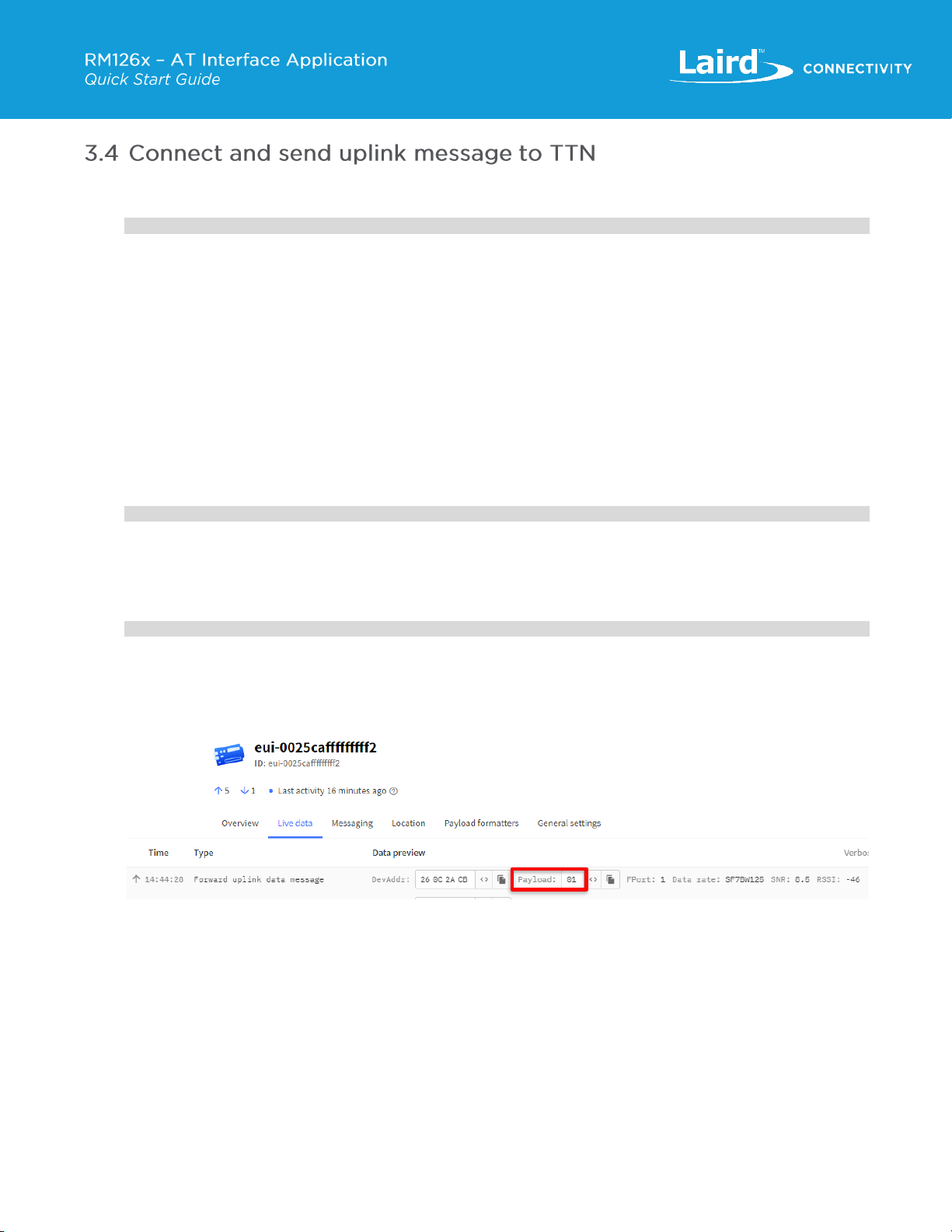
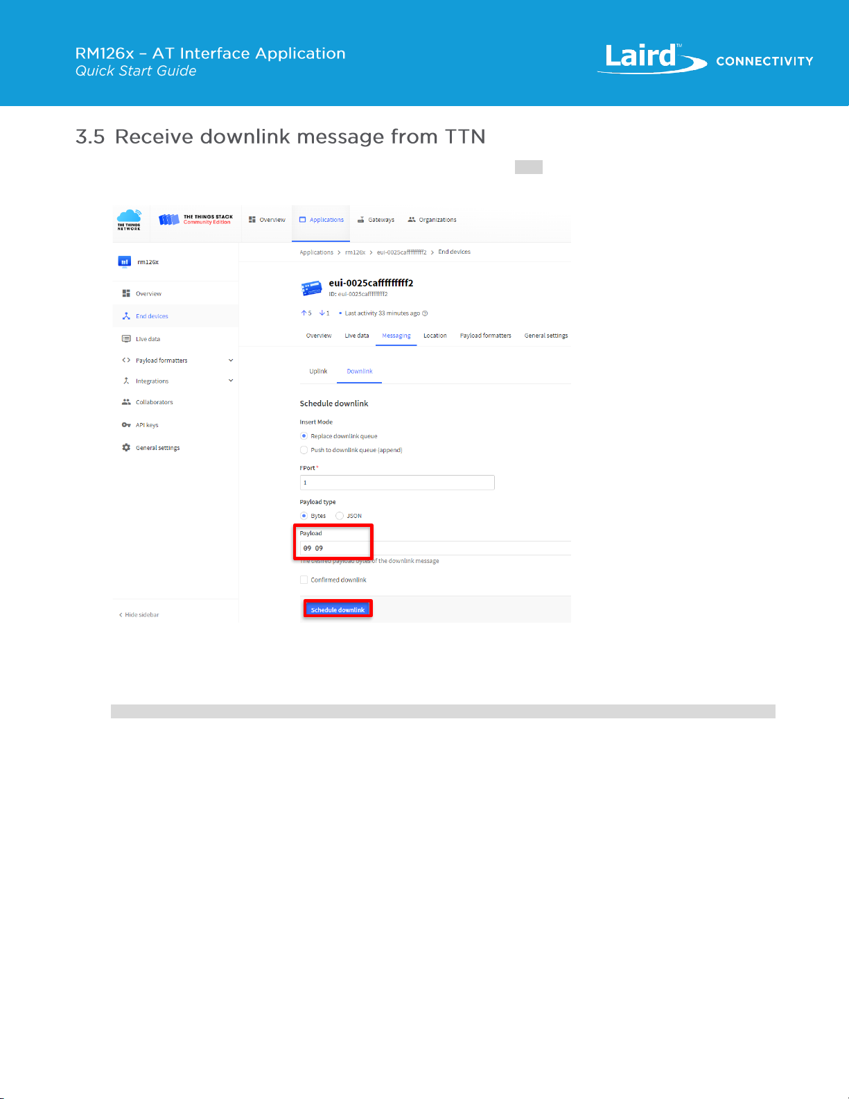
▪We will use The Things Network (TTN) as the Network Server in this document, however any network server should
work.
Software and Tools
1. The latest available version of the AT Interface application for RM126x can be found at:
https://github.com/LairdCP/RM126x_Firmware/releases.
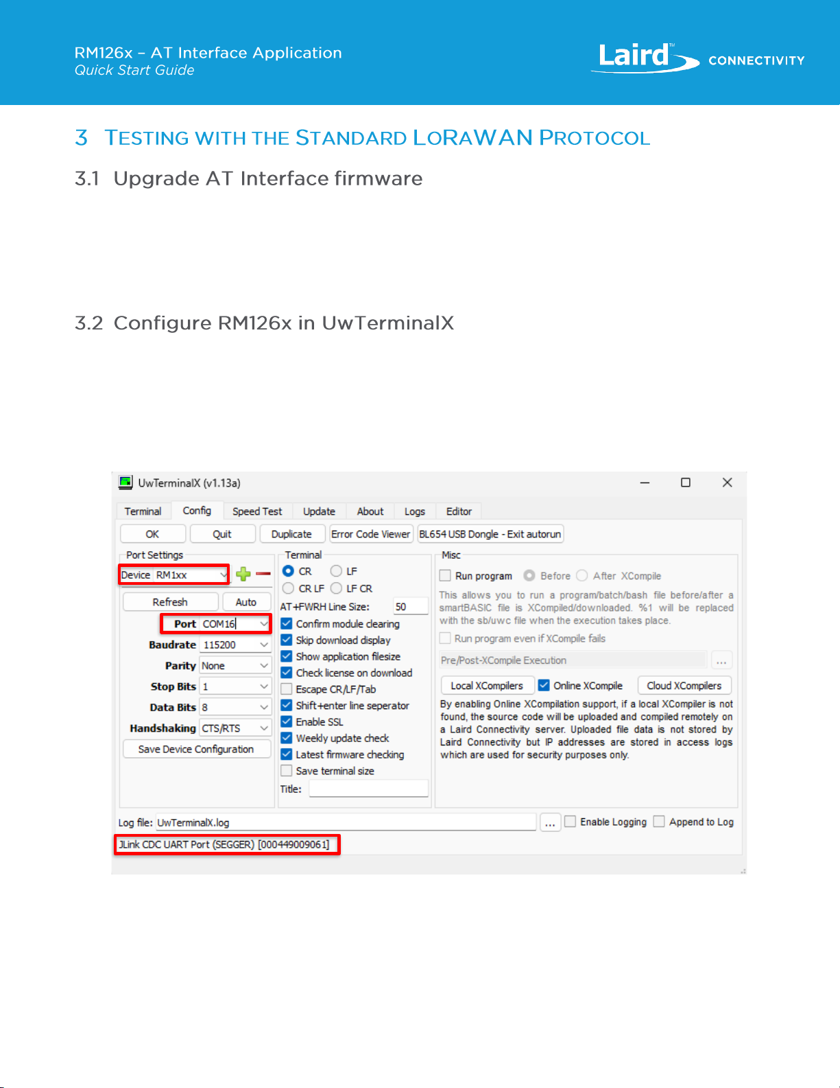
2. (Recommended) UwTerminalX v1.13a or later: https://github.com/LairdCP/UwTerminalX/releases.
You can also use other terminal programs such as TeraTerm, PuTTY or RealTerm.
Note: The RM126x development boards will show up as a JLink CDC UART Port (SEGGER) device in the Windows
device manager under “Ports (COM & LPT)”. If the driver is not installed automatically when the DVK is plugged
into your Windows PC, we recommend installing Simplicity Studio 5 or the latest version of the J-Link Software and
Documentation Pack.

https://www.lairdconnect.com/
3
© Copyright 2023 Laird Connectivity
All Rights Reserved
The RM126x modules should be updated with the latest version of the AT Interface application to fully utilize all the features of
the AT command set. The firmware version loaded to the RM126x module can be verified by sending the “ATI 3” command in
UwTerminalX (Figure 5) to confirm it matches the latest release version which can be found in
https://github.com/LairdCP/RM126x_Firmware/releases.
This quick start guide document assumes that you are familiar with programming firmware for RM126x. The further information
and instructions can be found in User Guide - Firmware Options and Upgrading - RM126x Series.
Before getting started, complete the following setup:
1. Attach the included external antenna to MHF4 connector.
2. Connect your RM126x development board to your PC via the included USB micro cable, and make sure that the blue
“J-Link” LED is active on RM126x DVK.
3. Launch UwTerminalX.exe on your development PC. From the Config tab in the Device drop-down menu, select
RM1xx under Port Settings. This will auto-populate the connection settings (baudrate, parity, stop bits, data bits and
handshaking) with the exception of the Port.
Figure 3: UwTerminalX: Settings & Config window

https://www.lairdconnect.com/
4
© Copyright 2023 Laird Connectivity
All Rights Reserved
4. Press Refresh and select the COM Port which your RM126x development kit was assigned by Windows Device
Manager. In the bottom-left corner of UwTerminalX you should see JLink CDC UART Port (SEGGER).
5. Please keep all other Settings and click Save Device Configuration followed by OK to advance to the Terminal tab.
6. Type AT into the terminal and press Enter. If you see the return value OK, then you are successfully communicating
with your RM126x over UART.
7. Retrieve DevEUI using AT%S 501? The output below is an example and your DevEUI will be different.
AT%S 501?
0025CAfffffffff2
Note: This step is not required if firmware is upgraded via UART. If you upgrade firmware through SWD, the radio will
DevEUI will be erased. Therefore, the value of the pre-programmed DevEUI should be stored so that it can be re-
programmed in later step. Alternatively, you can scan the QR code on the module label which contains this DevEUI
value.
Also, in the firmware version 127.4.1.421 and 128.4.1.421, DevEUI is erased when AT&F is called. In later
firmware, this will be fixed so that DevEUI will persist over AT&F.

https://www.lairdconnect.com/
5
© Copyright 2023 Laird Connectivity
All Rights Reserved
8. Next, perform a factory reset with the AT&F command. This will set all writable parameters to their default values and
perform a warm reset.
Figure 4: UwTerminalX: AT and AT&F command usage

https://www.lairdconnect.com/
6
© Copyright 2023 Laird Connectivity
All Rights Reserved
9. In the next step, we are requesting the RM126x module name and firmware version with the ATI command:
ATI 0
RM1262
ATI 3
128.4.1.391
Figure 5: UwTerminalX: ATI command usage
10. Configure the RM126x to enable the radio to connect to LoRaWAN Network Server via a LoRaWAN Gateway.
First, set the S register to configure the region for the desired country using the ATS 611=x, where x is the number of
the selected region as per the below selections:
▪RM1261 only:
–1: EU_EU868
–2: UK_EU863_870
–8: TAIWAN_AS923_1
–9: JAPAN_AS923_1
–11: INDIA_IN865_867
▪RM1262 only:
–3: USA_CANADA_US902_928
–4: AUSTRALIA_AU915_928
–5: AUSTRALIA_AS923_1
–6: NEW_ZEALAND_AS923_1
–7: NEW_ZEALAND_AU915_92
ATS 611=3

https://www.lairdconnect.com/
7
© Copyright 2023 Laird Connectivity
All Rights Reserved
11. Check if the pre-programmed DevEUI is set with”AT%S 501?”
AT%S 501?
If “0000000000000000” is returned, the DevEUI has been erased. Set 64 bit (16 hexadecimal characters) of the
LoRaWAN Dev EUI that you retrieved in step 7.
AT%S 501="0025CAfffffffff2"
Set the 64 bit (16 hexadecimal characters) LoRaWAN Join EUI. Replace the string value, between the quotes, with
your own user defined value.
AT%S 502="0025CA0000000001"
Set the 128 bit (32 hexadecimal characters) LoRaWAN AppKey EUI. Replace the string value, between the quotes,
with your own user defined value.
AT%S 500="0025CA00000000010025CA0000000001"
12. Save parameters to non-volatile memory and reset the module by performing a warm reset.
AT&W
OK
ATZ
OK
Note: RM126x uses Class A by default, therefore it was not necessary to configure it. If it is necessary to test with Class
B or C, S Register 603 can be used to configure the Class setting using the following syntax:
ATS 603=<value>
where <value> is 0 for Class A, 1 for Class B and 2 for Class C.
The Laird Connectivity RG1xx Gateway does not support Class B, therefore, if you are testing with this Gateway
only Class A or Class C should be configured.
This section assumes you know how to configure your gateway and register the RM126x and gateway to your network server.
For demonstration purposes this App Note uses RG1xx for the LoRaWAN Gateway and TTN for the Network Server. For
additional information on configuring RG1xx and TTN Network Server please reference Application Note - Setting up Basic
station on the Things Stack v3..

https://www.lairdconnect.com/
8
© Copyright 2023 Laird Connectivity
All Rights Reserved
1. Join the TTN network
AT+JOIN
JOIN: [OK], [TX]: C:11, F:904500000Hz, DR:0, [RX]: W:1, C:3, F:925100000Hz, DR:10
▪OK: RM126x received Join Accept from server and thus join process succeeded.
▪For [Tx]
–C: channels used to send Join Request
–F: Frequency used to send Join Request
–DR : data rate used to send Join Request
▪For [Rx]
–W : window to receive Join Accept –either Rx1 or Rx2
–C : channel used to receive Join Accept
–F : frequency used to receive Join Accept
–DR : data rate used to receive Join Accept
Or if the join fails, it will return a response in the following format:
AT+JOIN
JOIN: [FAIL], [TX]: C:15, F:905300000Hz, DR:0
2. To send uplink data from the RM126x to LoRa Network Server (such as TTN) use the command AT+SEND "<UPLINK
DATA IN HEX FORMAT>" as shown below.
AT+SEND "01"
TX: [ACK], C:10, F:904300000Hz, DR:3
3. Confirm the LoRa Network Server received the data under the Application/End Device/Live Data as shown in the
example below from TTN.
Figure 6: End device’s live data page on TTN

https://www.lairdconnect.com/
9
© Copyright 2023 Laird Connectivity
All Rights Reserved
1. On TTN, enter the string you want to send down to the RM126x module (0909 in the example below). On TTN Network
Server this can be scheduled under: Application > End Devices > Messaging > Downlink, and click Schedule
Downlink.
Figure 7: Schedule downlink from TTN
2. The LoRaWAN end device can receive data only after it sends uplink data in Class A, therefore to RX the downlink
packet, send another uplink message from the RM126x node.
AT+SEND "01"
TX: [ACK], C:13, F:904900000Hz, DR:3
3. The RM126x will show the received downlink message.
RX: W:1, P:1, C:5, F:926300000Hz, DR:13, 0909
▪W : window to receive downlink message - either Rx1 or Rx2
▪P: port at which downlink messsage arrived
▪C: channels used to receive downlink
▪F: frequency used to receive downlink
▪DR : data rate used to receive downlink

https://www.lairdconnect.com/
10
© Copyright 2023 Laird Connectivity
All Rights Reserved
It is possible to use up to 64 devices in a P2P network, but we will use 3 devices in this example to demonstrate P2P
functionality.
Each P2P peer is assigned a unique device address in ascending order beginning with 0. We will call the first device node0,
the second device node1 and the third device node2. The node0 will send out beacons, based on which other peers (e.g.
node1, node2) will synchronize timing in order to schedule transmit and receive slots.
IMPORTANT: When testing P2P functionality with two or more RM126x modules which are in close proximity (within 4-5
feet) of each other, Tx power should be set to its lowest setting of 1 dBm. Testing with a higher TX power
could result in damaging the radios due to RF energy saturation on the receiver, from which the radio may
not be recoverable. Setting TX power to 1dBm is covered in the parameter settings below.
1. Plug in each of the three RM126x DVK to USB ports in your computer and access them through a serial terminal with
proper configuration, as explained in 3.2 Configure RM126x in UwTerminalX above.
Figure 8: Three RM126x prepared for P2P test
2. On node1, enter the following commands.
Commands
Description
AT&F
Factory reset the RM126x (Optional –this will restore module to default settings)
ATZ
Soft reset
ATS 603=3
Set node1 for P2P mode
ATS 611=3
Set region to US (See AT Interface User Guide for correct Region setting if not US)
ATS 700=1
Set P2P Device address to 1 for node1
ATS 701=3
Set P2P network size to 3 (Should be equal to the number of nodes in the network including 0)
ATS 703=2
Set P2P data rate to DR2 (See AT Interface User Guide for Alternative data rate options)
ATS 704=0
Set P2P Listen duration to 0 which enables Class C listening.
ATS 705=0
Set P2P listen frequency to 0 which enables Class C listening behavior
ATS 706=2
Set P2P Beacon data rate to DR2 (See AT Interface User Guide for Alternative data rate
options)
ATS 708=1
Set P2P Tx power to 1dBm (The reduced Tx power is used here in assumption that your two
RM126x are in close proximity.)
AT&W
Save parameters to non-volatile memory
ATZ
Soft reset

https://www.lairdconnect.com/
11
© Copyright 2023 Laird Connectivity
All Rights Reserved
Commands
Description
ATS 707=20
Set allowed P2P Packet size. Note that this value may differ for each country. It should be
lower than value returned by “ATI 4003”
ATS 702=26
Set P2P Windows length. Note that this value may differ for each country. It should be
higher than value returned by “ATI 4005”
AT&W
Save parameters to non-volatile memory
ATZ
Soft reset
AT+P2PS
Start P2P session. The node1 will start listening for synchronization events.
3. On node2, enter the following commands.
Commands
Description
AT&F
Factory reset the RM126x (Optional –this will restore module to default settings)
ATZ
Soft reset
ATS 603=3
Set node2 for P2P mode
ATS 611=3
Set region to US (See AT Interface User Guide for correct Region setting if not US)
ATS 700=2
Set P2P Device address to 2 for node2
ATS 701=3
Set P2P network size to 3 (Should be equal to the number of nodes in the network including 0)
ATS 703=2
Set P2P data rate to DR2 (See AT Interface User Guide for Alternative data rate options)
ATS 704=0
Set P2P Listen duration to 0 which enables Class C listening.
ATS 705=0
Set P2P listen frequency to 0 which enables Class C listening behavior
ATS 706=2
Set P2P Beacon data rate to DR2 (See AT Interface User Guide for Alternative data rate
options)
ATS 708=1
Set P2P Tx power to 1dBm (The reduce Tx power is used here in assumption that your two
RM126x are in proximity.)
AT&W
Save parameters to non-volatile memory
ATZ
Soft reset
ATS 707=20
Set allowed P2P Packet size. Note that this value may differ for each country. It should be
lower than value returned by “ATI 4003”
ATS 702=26
Set P2P Windows length. Note that this value may differ for each country. It should be
higher than value returned by “ATI 4005”
AT&W
Save parameters to non-volatile memory
ATZ
Soft reset
AT+P2PS
Start P2P session. The node1 will start listening for synchronization events.
4. On node0, enter the following commands.
Commands
Description
AT&F
Factory reset the RM126x (Optional –this will restore module to default settings)
ATZ
Soft reset
ATS 603=3
Set node0 for P2P mode
ATS 611=3
Set region to US (See AT Interface User Guide for correct Region setting if not US)
ATS 700=0
Set P2P Device address to 0 for node0

https://www.lairdconnect.com/
12
© Copyright 2023 Laird Connectivity
All Rights Reserved
Commands
Description
ATS 701=3
Set P2P network size to 3 (Should be equal to the number of nodes in the network including 0)
ATS 703=2
Set P2P data rate to DR2 (See AT Interface User Guide for Alternative data rate options)
ATS 704=0
Set P2P Listen duration to 0 which enables Class C listening.
ATS 705=0
Set P2P listen frequency to 0 which enables Class C listening behavior
ATS 706=2
Set P2P Beacon data rate to DR2 (See AT Interface User Guide for Alternative data rate
options)
ATS 708=1
Set P2P Tx power to 1dBm (The reduce Tx power is used here in assumption that your two
RM126x are in proximity.)
AT&W
Save parameters to non-volatile memory
ATZ
Soft reset
ATS 707=20
Set allowed P2P Packet size. Note that this value may differ for each country. It should be
lower than value returned by “ATI 4003”
ATS 702=26
Set P2P Windows length. Note that this value may differ for each country. It should be
higher than value returned by “ATI 4005”
AT&W
Save parameters to non-volatile memory
ATZ
Soft reset
AT+P2PS
Start P2P session. The node0 will broadcast beacons for synchronization events.
5. On node0, transmit data to node1 over P2P connection with unicast.
AT+P2PT 1,”00AA”
On the node1, the transmitted message will appear.
RX: [P2P] S:0, 00AA
Where S :0 indicates the P2P packet was received from Node 0, followed by the data, 00AA.

https://www.lairdconnect.com/
13
© Copyright 2023 Laird Connectivity
All Rights Reserved
6. This time, we broadcast a message from node1.
AT+P2PT 64,”00BB”
Node0 and node2 will receive the message with some time delay.
RX: [P2P] S:1, 00BB
Where S:1 indicates the P2P packet was received from Node 1, followed by the data, 00BB
7. End P2P connection when P2P test is done. Issue this command on all nodes - node0, node1 and node2.
AT+P2PE

https://www.lairdconnect.com/
14
© Copyright 2023 Laird Connectivity
All Rights Reserved
Version
Date
Notes
Contributor(s)
Approver
1.0
10 Oct 2023
Initial Release
Seokwoo Yoon
Rikki Horrigan
Senthooran
Ragavan
Other manuals for RM126 Series
1
This manual suits for next models
2
Other Laird Recording Equipment manuals