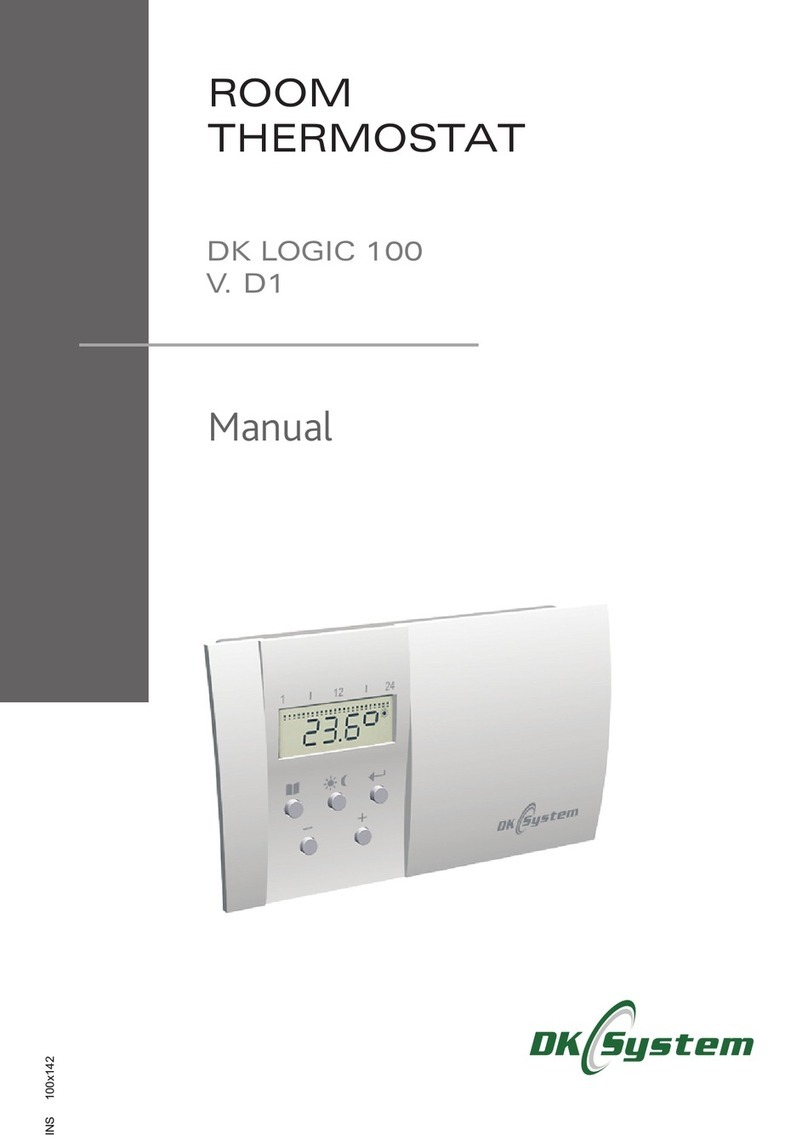
DK System DK LOGIC 200 User manual

WIRELESS
ROOM
THERMOSTAT
DK LOGIC 200
Manual
INS-012-005 130X184,5

Wireless room thermostat DK LOGIC 200
2
Table of Contents
1. Description of a thermostat...................................................................
2. Notes on installation...............................................................................
3. Description of the transmitter components - display..........................
4. Description of the transmitter components - buttons.........................
5. Thermostat installation - transmitter.....................................................
6. Description of the receiver components..............................................
7. Installation and connection of the receiver to electrical system.......
8. Receiver encoding..................................................................................
9. Interferences - communication error....................................................
10. Description of LEDs singalling system..............................................
11. Options of the thermostat - transmitter..............................................
12. First start...............................................................................................
13. PROG mode - programming for automatic operation......................
13.1 Program Pr. 1 and Pr. 2.....................................................................
13.2 Program Pr.3 - user settings..............................................................
13.3 Example - programming the automatic operation mode....................
14. Momentary temp. change in automatic mode....................................
15. MANU mode - manual operation mode...............................................
16. TEST function........................................................................................
17. Protection against freezing function...................................................
18. CLO mode - setting the current hour and day....................................
19. PAr1 mode - a parameter visible on a main screen...........................
20. PAr2 mode - program version and RESET..........................................
21. Setting a default day and night temperature......................................
22. OFF function.........................................................................................
23. Battery replacement.............................................................................
24. Faults.....................................................................................................
25. Technical data - transmitter.................................................................
26. Technical data - receiver......................................................................
27. Table of programs.................................................................................
28. Rules of conduct with waste electrical and electronic equipment..
3
3
4
5
5
6
7
8
8
9
9
10
10
11
11
12
15
15
15
16
16
16
17
18
18
18
19
20
20
21
23

3
Wireless room thermostat DK LOGIC 200
1. Description of a thermostat
2. Notes on installation
A wireless room thermostat DK LOGIC 200 is designed for automatic adjustment
of temperature in a room by switching on/off of the boiler.
The thermostat is equipped with a relay output, which sends an on / off signal
when the pre-set temperature has been exceeded.
A device has the following features:
q ability of selecting different programs for each day of the week
q two factory pre-set programs
q two selectable temperature - day and night
q six heating periods per day
q easy and intuitive programming
q possibility of short-term changes in heating temperature
q easy installation
q frost protection
q heater adjustable every 0.5 °C
q multifunction display
q memorizing all the settings, even in the long-term absence of batteries
q The device must be installed by an authorized person.
qIt is required that the boiler had its own safeguards against excessive
temperature rise of the boiler caused e.g. boiler controller or related
equipment malfunction.
qThe controller should be placed in a location that prevents its heating to a
temperature higher than 40 °C.
qThe controller must not be exposed to water and conditions causing
condensation (e.g. sudden changes in ambient temperature).
qThe device should be installed and operated as described in the assembly
description and rules for electrical equipment.

4
Wireless room thermostat DK LOGIC 200
2. Notes on installation (cont.)
q Before starting the transmitter and receiver, you should check the electrical
connections.
q Connection of the power cord should be made with the device powered off (a
power plug must be disconnected from the mains). Connection of the devices
with the mains plug of the controller plugged in creates an electric shock.
q You must not use a damaged devices.
3. Description of the transmitter components - display
Fig. 1 Display components
1. Flashing point indicating the current time
2. Indication of the option currently in use: AUTO, MANU, PROG
3. Indication of protection against freezing
4. Display of temperature or time
5. Indication of boiler operation
6. Indication of the lowered temperature (night mode)
7. Indication of the comfort temperature (day mode)
8. Graphic presentation of the selected program
1
2
3
6
7
5
8
AUTO
MANU
PROG P
T
4
Note: The “room thermostat service” option must be turned on in
the programmer after the thermostat has been connected to the
boiler's programmer.
!

5
Wireless room thermostat DK LOGIC 200
4. Description of the transmitter components - buttons
5. Thermostat installation - transmitter
Thermostat DK LOGIC 200 should be located in a place not exposed to other
sources of heat (radiator, fireplace, etc.), affecting the accuracy of the
temperature readout in the room. The device consists of two parts: front - a
microprocessor and rear - connector.
1. Menu
2. Setting the temperature (comfort / lowered), operation in a manual mode,
operation in an anti-freezing mode
3. Confirmation; additionally in AUTO mode, when the button is pressed the
pre-set temperature, time and a day of the week are displayed
4. Change of functions or pre-set values.
1 2 3
4
1. Detach the front and back parts of the thermostat.
2. Install the back part directly on a wall.
3.Put two 2 x 1.5 V alkaline batteries type AA / LR6 into the front part of the
thermostat.
4.Put the front and back part together - a thermostat is ready for
programming.
Fig. 2 Description of the transmitter's buttons

6
Wireless room thermostat DK LOGIC 200
6. Description of the receiver components
Fig. 3 Description of the receiver components
1
N LRE1
23
4
5 5
6 7 8
POWER SUPPLY
INTERFERENCES
RE1
1. Green diode - POWER SUPPLY
2. Blue diode - COMMUNICATION
3. Red diode - INTERFERENCES
4. Orange diode - RE1 boiler relay
5. Installation slots
6. FUNCTIONS button
7. RE1 - clamps to install the boiler wires
8. NL - power supply clamps ~230 V, 50 Hz

7
Wireless room thermostat DK LOGIC 200
7. Installation and connection of the receiver to electrical
system
1. Open the front part of the receiver housing.
2. Using two screws and dowels attach the receiver to the wall.
3. Turn off the voltage on a wire feeding the receiver.
4. Connect the cables between a boiler or a programmer and a RE1 clamp in the
receiver (Fig.4).
5. Connect the feeder cable with the appropriate clamps in the receiver (Fig.4):
-a blue wire must be connected to the N clamp (“neutral”)
-a brown wire must be connected to the L clamp (“phase”)
6. Close the front part of the receiver housing.
7. Turn the power on - a green diode POWER SUPPLY should lit on the receiver,
informing on the correct connection.
Note: As the radio interferences are possible, it is recommended to
install the receiver at least 0.5m from large metal objects and
electrical quads
!
Fig. 4 Diagram of the receiver connections to the boiler/programmer and to
the electrical system
N LRE1
RE1
~ 230 V, 50Hz
Boiler or
programmer
POWER SUPPLY
INTERFERENCES

8
Wireless room thermostat DK LOGIC 200
8. Receiver encoding
9. Interferences - communication error
A transmitter and receiver, which can be found in a single original box, have been
pre-set in the factory to use thus their encoding is not necessary.
If needed, the encoding steps described below must be followed:
Radio wave interferences may occur sporadically,
which can lead to a lack of communication
between the receiver and the transmitter. If this
happens, a red INTERFERENCES diode starts to
blink on a receiver and an Err1 message will be
displayed on the transmitter screen.
To restore communication follow the steps
described in the encoding process - see point 8
Receiver encoding.
1. Press and hold for 5 sec. the FUNCTIONS button - the memory will reset -
a blue and red diodes will lit at the same time. Once the memory is cleared, a
red diode INTERFERENCES will flash.
2. Press and hold for 1.5 sec. the FUNCTIONS button - the receiver will go to
a standby mode waiting for a code to be introduced - a blue and red diodes
will be flashing alternately.
3. At that time, a TEST function must be called on the DK LOGIC 200
transmitter. A code will be directed to a receiver: two diodes blue and red will
blink twice at the same time.
4. Next, a short communication test will be made - the RE1 relay will be
connected twice and an orange diode will be lit.
5. The transmitter and receiver set has been properly configured.

Wireless room thermostat DK LOGIC 200
9
11. Options of the thermostat - transmitter
10. Description of LEDs singalling system
AUTO Automatic mode - a thermostat works by the
pre-set program in line with the adjusted
day and night mode temperature.
MANU Manual mode - allows adjustment of the
heating temperature without interfering in
the pre-set program.
CLO Hour and day setting mode.
MANU
AUTO
PROG Time range programming mode for a day
and night temperature.
PROG
PAr1 A setting mode of the permanently visible
parameter (hour and temperature).
GREEN diode is on receiver well connected to the grid
BLUE diode blinks sending or receiving the signal
RED diode blinks no encoding - memory is empty
RED diode is on interferences
ORANGE diode is on RE1 relay is shorted
BLUE and RED diodes blink alternately waiting for the code
BLUE and RED diodes blink at the same time receiving the code
BLUE and RED diodes are on at the same time erasing the memory
PAr2 Program # and RESET.
OFF Turning off thermostat operation.

Wireless room thermostat DK LOGIC 200
10
12. First start
13. PROG mode - programming for automatic operation
1. When the batteries are in, the display will show
0:00 hours, and the thermostat will work in P1
mode - see point 13 “PROG mode - program-
ming the automatic operation mode”.
1. Press twice until the PROG appears on
the screen. Confirm by pressing .
AUTO
2. Use the “-/+” buttons to set the actual hour.
Confirm by pressing ; To set minutes,
please follow the same procedure. Confirm by
pressing . A screen showing the current
day of the week will be shown.
t
t
3. Use the “-/+” buttons to set the actual day of the
week. Confirm by pressing . The controller
will show the main screen, taking into account
the introduced settings. The controller is in the
P1 program - see point 13 “PROG mode -
programming the automatic operation
mode”, using the default settings of the
comfort temperature (day) at the level of 21°C
and the lowered temperature (night) at the level
of 18°C. The way of changing the default
tempe-ratures has been described in the point
21 “Setting the default day and night tempe-
rature”.
AUTO
t
2. Use “-/+” to select one of the programmes (Pr.
1, Pr. 2 or Pr. 3) and confirm by pressing
For Pr. 1 and Pr. 2, the controller will go to to the
main screen view; For Pr. 3 the proces of
individual settings programming must be
continued.
.
PROG
t
PROG
PROG

11
Wireless room thermostat DK LOGIC 200
13.1 Program Pr. 1 and Pr. 2
AUTO
The Pr. 1 program carries out the heating process
between 6.00 and 23.00 hrs. in all days of the
week.
AUTO
The Pr. 2 program carries out the heating process
between 6.00 and 8.00 and from 16.00 to 23.00 by
five days of the week (Mon-Fri). On Saturday and
Sunday the heating takes place between 6.00 and
23.00 hrs.
AUTO
13.2 Program Pr.3 - user settings
1. Once the Pr. 3 is confirmed, a d:1 will appear on
the screen indicating that the system is ready
for setting the program to Monday (the first day
of the week).
PROG
PROG
d.1 Monday 1:U1, 1:U2, 1:U3, 1:U4, 1:U5, 1:U6
d.2 Tuesday 2:U1, 2:U2, 2:U3, 2:U4, 2:U5, 2:U6
d.3 Wednesday 3:U1, 3:U2, 3:U3, 3:U4, 3:U5, 3:U6
d.4 Thursday 4:U1, 4:U2, 4:U3, 4:U4, 4:U5, 4:U6
d.5 Friday 5:U1, 5:U2, 5:U3, 5:U4, 5:U5, 5:U6
d.6 Saturday 6:U1, 6:U2, 6:U3, 6:U4, 6:U5, 6:U6
d.7 Sunday 7:U1, 7:U2, 7:U3, 7:U4, 7:U5, 7:U6
dP.P Mon-Fri PP:U1, PP:U2, PP:U3, PP:U4, PP:U5, PP:U6
dS.n Sat, Sun Sn:U1, :U2, :U3, :U4, Sn:U5, Sn:U6
dP.n entire week Pn:U1, :U2, :U3, :U4, Pn:U5, Pn:U6
Sn Sn Sn
Pn Pn Pn
Note: For each day of the week it is possible to set max. three day
and night temperature periods, and its change is possible after at
least 10 minutes (which is the minimum programmable time). They
can be set in the following daily programmes:
!

12
Wireless room thermostat DK LOGIC 200
13.2 Programme Pr.3 - user settings (cont.)
2. Use the “-/+” to choose a day (range of days) to
be programmed (acc. to the matching above)
and confirm with . For d:1, 1:U1 will be
displayed on a screen (and in the same manner
for all remaining programmes, in line with the
matching above), next, an hour will be
displayed for which a start of the first day or
night temperature ranges in a given day must
be determined.
3. Use the “-/+” buttons to set the hour when the
first temperature range starts, and the buttons
to check what temperature - comfort (day)
or lowered (night) is about to start at a given
hour - a corresponding symbol (Sun) or
(Moon) will be displayed on a right side of the
screen.
.
.
t
PROG
PROG
PROG
PROG
PROG
PROG
4. Confirm the settings by pressing ; A symbol
of another temperature range in a given day will
be displayed on a screen (e.g. 1:U2), and then
the hour when it should start - the setting is
carried out as described above.
5. All the remaining temperature ranges are being
set in the same way.
t
6. Once the settings are done, press twice
until the main scree is shown. AUTO
A thermostat will be programmed for the entire
week between 6 - 9 and 16 - 21 and a daily tempe-
rature of 22°C will be set; for the remaining period
of the day, a lowered temperature of 17°C, as per
the diagram below, will be set.
17
22
°C
hours6 9 16 21
13.3 Example - programming the automatic operation mode

13
Wireless room thermostat DK LOGIC 200
13.3 Example - programming the automatic operation mode (cont.)
1. Set the values of a day and night temperature
as described in point 21 “Setting the default
day and night temperature”.
2. Press twice till the PROG symbolsis shown
on a screen and confirm by pressing .
4. Use the “-/+” buttons to select the dP.n range
(from Monday to Sunday) and confirm by
pressing . Pn.U1 will be displayed, and
then an hour for which the start of the first day or
night temperature range in this period must be
displayed
t
3. Use the “-/+” buttons to select the Pr. 3 and
confirm by pressing . A d.1 symbol will be
displayed.
t
PROG
PROG
t
PROG
PROG
PROG
PROG
PROG
5. Use the “-/+” buttons to set the hour to 6:00; and
the buttom to set the symbol and
confirm by pressing . A symbol of the next
range Pn:U2 will appear on the screen, and
next the hour at which it should start.
t
PROG
6. Use the “-/+” buttons to set the hour to 9:00; and
the button to set the symbol and confirm
by pressing . A symbol of the next range
Pn:U3 will appear on the screen, and next the
hour at which it should start.
tPROG

14
Wireless room thermostat DK LOGIC 200
13.3 Example - programming the automatic operation mode (cont.)
PROG
7. Use the “-/+”buttons to set the hour to 16:00;
and the button to set the symbol and
confirm by pressing . A symbol of the next
range Pn:U4 will appear on the screen, and
next the hour at which it should start.
t
PROG
PROG
PROG
PROG
8. Use the “-/+” buttons to set the hour to 21:00;
and the button to set the symbol and
confirm by pressing . A symbol of the next
range Pn:U5 will appear on the screen, and
next the hour at which it should start.
tPROG
PROG
9. Confirm by pressing (w/o introducing any
changes). A symbol of the next range Pn:U6
will appear on the screen, and next the hour at
which it should start.
t
PROG
PROG

15
Wireless room thermostat DK LOGIC 200
13.3 Example - programming the automatic operation mode (cont.)
Note: If no changes are made for three minutes in the PROG mode,
the controller will automatically go to the AUTO mode.
!
14. Momentary temp. change in automatic mode
This function allows temporary change of the heating temperature set in AUTO
mode. It can be made by pressing the “-/+” buttons; such a temperature will be
maintained until the activation of the next program.
10. Without making any changes, press for a
few times until the main screen is shown. AUTO
15. MANU mode - manual operation mode
The MANU mode allows changing the heating temperature without interfering
with the set program.
2. Use the “-/+” button to set the required
temperature; a thermostat will keep it until the
next manual change or switching the controller
to the automatic mode.
1. Press the button for a few Times till the
MANU symbol and temperature appears. MANU
MANU
3. After a while, the controller will automatically
switch to perform manual settings, and the
screen will show the current measured
temperature or hour (depending on setting the
Par1 - see point 19 “PAr1 - parameter visible
on the main screen”).
MANU
16. TEST function
The TEST function allows controlling the proper
connection of the controller to the boiler or
programmer.
Press the button , and then . TEST will be
displayed on a screen, and the controller will
perform several cycles of turning the boiler on and
off - the function active in AUTO and MANU mode.
MANU
P

Wireless room thermostat DK LOGIC 200
16
17. Protection against freezing function
This function allows protecting the installation against freezing and turns the
boiler on when the room temperature drops below 3 °C.
T
T
1. Press the button for a few times till and
a temperature of 3 °C appears on the screen
T
2. After a while, the controller will automatically
switch to perform the protection against
freezing function and the screen will show the
current measured temperature or hour (depen-
ding on setting the PAr1 - see point 19 “PAr1 -
parameter visible on the main screen”).
18. CLO mode - setting the current hour and day
1. Press the button for a few times till CLO
symbol appears on the screen. Confirm by
pressing .
t
2. An indication of hour is blinking on a screen -
this can be set by using the “-/+” buttons and
confirmed by pressing . Next, following the
same steps, the minutes can be set and
confirmed by pressing .
t
t
3. An indication of a day of the week is blinking on
a screen - this can be set by using the “-/+”
buttons (d:1 - Monday; d:2 - Tuesday, etc.) and
confirm by pressing - after a while, the
controller will switch to the main screen view.
19. PAr1 mode - a parameter visible on a main screen
PAr1 - selection of parameter displayed on the screen during operation of the
thermostat (hour / temperature).
1. Press the button for a few times till Par1
appears on the screen. Confirm by pressing
.
t

Wireless room thermostat DK LOGIC 200
17
20. PAr2 mode - program version and RESET
PAr2 - shows the program version installed in the controller. Additionally, in this
mode, it is possible to reset all the settings of the thermostat.
19. PAr1 mode - a parameter visible on a main screen (cont.)
2. One of the following symbols will appear on the
screen: C - means that the time will be seen on
a main screen; t - means that the temperature
will be seen on a main screen. Choose the
required option by pressing the “-/+” buttons
and by confirming with after a while, the
controller will switch to the main screen view.
1. Press the button for a few times till the PAr2
symbol appears. Confirm by pressing .
t
2. A number of the installed program, e.g. 10.04
will appear on the screen. Pressing the button
will cause the controller to switch to the
main screen view.
20.1 RESET
If necessary, it is possible to reset all the settings, returning to the factory
controller. To do this:
1. Go to the view of the program number.
2. Press and hold the “-” button for a few seconds;
RES will appear on the screen, and after a while
the controller will switch to the main screen
view - it will be working on the factory (default)
settings, realizing the Pr1 program.

AUTO
18
Wireless room thermostat DK LOGIC 200
21. Setting a default day and night temperature
1. Press the button ; currently set default
comfortable temperature (day) will appear on
the screen - the factory pre-set temperature is
21°C. Use the “-/+” buttons to set the parame-
ters as per the user’s request; use the to
confirm and to switch to the main screen; press
to go to the default settings of the lowered
(night) temperature
t
2. Current default lowered (night) temperature will
be displayed on a screen - the factory pre-set
temperature is 18°C. Use the “-/+”buttons to set
the parameters as per the user's request and
use to confirm; the controller will show the
main screen taking into account the introduced
settings.
t
22. OFF function
OFF function allows turning the thermostat off.
Press the button for a few times till OFF
appears on the screen and confirm by pressing
; the current measured temperature or time
will appear on the screen (depending on setting the
PAr1 - see point 19 PAr1 - parameter visible on the
main screen), which will be displayed alternating
with the OFF symbol.
t
Note: Disabling the OFF function, i.e. unlocking the controller
operation takes place by pressing the button - the controller will
return to work in AUTO mode.
!
23. Battery replacement
The need to replace the battery is indicated on the
display with the BATT symbol. Use the alkaline
batteries 2 x 1,5 V, type AA/ LR6.
AUTO

Wireless room thermostat DK LOGIC 200
19
Note: After replacing the batteries, a BATT symbol may appear on
the screen until the data and readings are reloaded in the controller.
Also, after replacing the batteries, please check and adjust the time
setting.
!
24. Faults
In the case of thermostat malfunction, before filing a complaint, please follow
a few steps to check the transmitter:
1. Check the battery level. If low, please replace the batteries - see point 23
“Battery replacement”. Pay attention to batteries polarity.
2. Check the terminals connecting the batteries with the thermostat plate.
Tighten the screws connecting the metal contacts of the thermostat (see
Fig. 5).
3. Check the position of the thermistor. Make it straight if bent (see Fig. 6).
4. Test the relay - see point 16 “TEST function”.
5. Eliminate the interference of radio waves, which can cause loss of com
munication between the transmitter and receiver - see point 7.
6. If necessary, carry out the receiver coding - see point 6 “Receiver enco-
ding”.
23. Battery replacement (cont.)
Fig. 5 Connection of the elements in a transmitter
AA / LR6
contacts screw
thermistor
Fig. 6 Incorrect location of the thermistor in a transmitter

Wireless room thermostat DK LOGIC 200
20
25. Technical data - transmitter
26. Technical data - receiver
Power alkaline batteries 2 x 1.5 V type AA / LR6
Number of programs 6 per day
Hysteresis 0.5°C
Min. programmable time 10 min.
Heating range from 5°C to 39°C
Temperature setting accuracy 0.5°C
Temperature measurement error +/- 0.5°C
Output max. 5 A / 250 V
Rated voltage 230 V, 50 Hz
Communication type bilateral
Frequency 433,92 MHz
Max. range 35 m (depending on the environment)
Transmitter output max. 5 A / 250 V
Protection class IP 20
Ambient temperature from 0°C to + 40°C
Table of contents
Other DK System Thermostat manuals