dlb AIJGO-34/COMP User manual

www.dlb.hu +36 27 502 555sales@destsa.hu
INSTRUCTION
MANUAL
AIJGO34/COMP
PERSONAL GROUNDING TESTER WITH PLATFORM,
DOUBLE DUAL FOOT ELECTRODE, RFID READER, LCD DISPLAY,
OPERATING SOFTWARE AND ENTRANCE GATE WITH TURNSTILE

TABLE OF CONTENTS
About the product ............................................ 3
Technical informations ........................................ 4
Parts of the tester ............................................. 6
Turnstile control system wiring guide .......................... 8
Items supplied with the tester .................................. 8
Packaging dimensions and weights of the product .............. 9
Assembly instructions ........................................10
Setting the operating direction of the tester ...................14
Operation instructions .......................................22
Calibration / verication guide ................................23

3
ABOUT THE PRODUCT
ӹTester for checking personal grounding before entering an ESD protected area
(EPA)
ӹTesting footwear system and wrist strap/groundable ESD smock system at the
same time
ӹCan be used to test a groundable ESD smock system
ӹTest result indication on LCD display, with LED light and sound
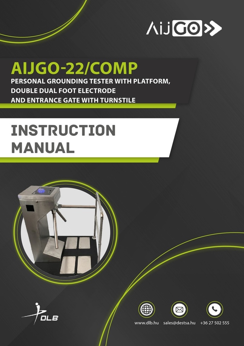
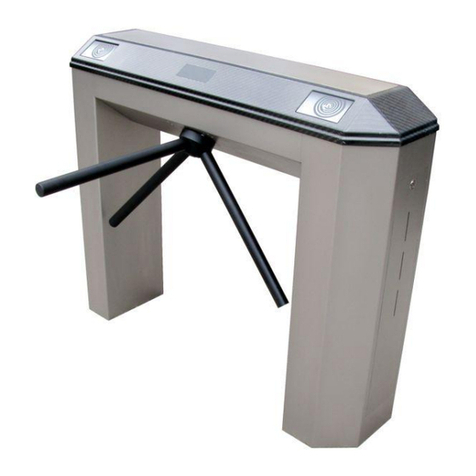
The AIJGO-34/COMP is a tester for checking personal grounding before entering an
ESD protected area (EPA). It may be a good choice if you want to identify persons
entering the site. Tester with LIGHT BAR system – such AIJGO products have a steel
touch button, the measured results are indicated by LED lights. Type with COMPLEX
system – these testers are supplied built-in in an entrance gate with turnstile.
COMFORT system product – such AIJGO devices have touch button and RFID reader,
an RFID card is required for use, which includes the type of test to be used. This type
can be: 1. Footwear system test 2. Wrist strap/groundable ESD smock system test 3.
Footwear system and wrist strap/groundable ESD smock system combined test 4.
VIP test. The test can start after the card has been scanned.
Thanks to the dual foot electrode, the tester simultaneously measures the resistance
of the right and left foot relative to the hand. After the test, the measured values are
displayed on the built-in LCD display. The measured results are stored on an internal
SD card. In the event of a power disconnection, the gate automatically drops down
its turnstile to allow free passage.
It is also possible to congure it so that a test can be carried out without touching the
touch button, but an RFID card is required in this case too. The product is supplied
with an operating software and can operate individually with this. If required, a
management software called PieManager can be purchased to congure it over a
LAN network and to retrieve the measured results. The system assigns a test method
to users and manages their identication data. It saves the entry data as .csv les
(compatible with Excel and text editor) and automatically logs daily events.
It is recommended and sucient to purchase only one management software if
several testers are purchased and networked. Purchasing and networking multiple
management software with multiple testers can lead to communication and system
malfunctions. If you have several testers and you do not network them, but use them
as separate devices, please buy individual software for each device to congure and
collect data over the LAN network.
The tester is supplied with manufacturer’s calibration certicate, platform, double
dual foot electrode and entrance gate with turnstile.

4
Resistance values indicated as acceptable by the tester
Default setting when measuring footwear system 100 KΩ – 100 MΩ
You can also set an upper value of 35 MΩ, see the PieManager management software description.
Default setting when measuring wrist strap/
groundable ESD smock system 750 KΩ – 35 MΩ
TECHNICAL INFORMATIONS
Gate properties
ӹManual rotation with mechanical assistance (rotary motor)
ӹRotation can be blocked electronically
ӹAutomatic turnstile drop down in the event of power disconnection
ӹConnectable to a re alarm system, it can be set to drop down the turnstile after
a signal from the system, allowing free passage through the gate.
ӹFor indoor use only
Operating system Linux Raspbian
The tester can be congured via LAN network
using RJ45 cable
Test voltage 100 V DC
Wrist strap/groundable ESD smock system
connection
With a combined 10 mm snap, 4 mm banana
plug socket
Power supply 230 V AC
Sizes 1000 x 950 x 1049,5 mm with platform and
touch button
CE declaration
We declare that the AIJGO-34/COMP product complies with the requirements of IEC
61340-5-1, ANSI/ESD S20.20 and Directive 2001/95/EC (General product safety).
Warning
The device can deliver an eective output power of up to 20 µA or less at a maximum
voltage of 100 V for 2-4 seconds at 0,5 second cycles. Therefore, persons with an
implanted electronic device (e.g. insulin pump, pacemaker, etc.), known or acute
hear rhythm disorders and other disorders of the heart’s impulse generation and
conduction, seizure disorders (e.g. epilepsy) should consult their doctor before using
this device.
It is forbidden to modify the device, both in terms of hardware and software.
Any modication to the product will void the warranty.

5
AIJGO-34/COMP Personal grounding tester with platform, double dual foot electrode, and
entrance gate with turnstile
AIJGO-BAR1 Barrier for AIJGO-22/COMP or AIJGO-34/COMP tester
AIJGO-OLED Optional gate opening touch button outwards
AIJGO-34/MSW
PieManager management software for AIJGO-34 and AIJGO-34/COMP (if
buying more than one tester, it is sucient and recommended to buy one if
they will be networked together)
Order codes

6
PARTS OF THE TESTER
1. Steel touch button with 9 RGB LEDs
2.
Combined 4 mm banana plug and 10 mm snap
socket for connecting wrist strap/groundable
ESD smock
3. LCD display
1
2
3
4
4
4. Speaker location
6
7
6. Cable for connecting foot electrodes 7. Connector to the common grounding point
of the gate
5
5. RFID reader

7
8
8. AIJGO-OLED - Optional gate opening touch
button outwards

8
TURNSTILE CONTROL SYSTEM
Wiring guide
The tester is supplied built-in in an
entrance gate
Arm dropping (Input)
Crossing conrmation
(Output, Normally Open)
Crossing conrmation (Input)
Output direction start (Input)
Input direction start (Input)
LED ( - )
LED direction 1 (Output)
LED direction 2 (Output)
LED Common (Output)
Output latch control
(Output 24V 1A)
Input latch control
(Output 24V 1A)
Arm motor (Output)
12V DC 1A (Output)
Power, 24V DC 2A
Turnstile control system
Platform with foot electrodes, foot
electrode cables
ITEMS SUPPLIED WITH THE TESTER

9
PACKAGING DIMENSIONS AND WEIGHTS OF THE
PRODUCT
SIze of the package Weight of the package
AIJGO-34/COMP - 1. package 112 x 48 x 45 cm 73 kg
AIJGO-34/COMP - 2. package with barrier 100 x 105 x 14 cm 56 kg
AIJGO-34/COMP - 2. package without
barrier 100 x 105 x 14 cm 53 cm
1. package
2. package

10
RFID reader (built-in)
Multifunctional unit that can handle cards that comply with most known RFID
standards:
LF reader (low frequency), 125/134 kHz types:
eMarine (EM4100, 4102, 4200), HID ProxCard II, Indala, Indala, Kantech, ISO 18000,
ISO 11784/85 HDX, ISO 11784/85 FDX(-B), TI RFID (Tiris, e.g. RI-TRP-R4FF, RI-TRP-W4FF),
Casi Rusco, HITAG 1/S, HITAG 2
HF reader (high frequency), 13,56 MHz types:
ISO-14443A type of encoders: Mifare Classic (1k/4k), Mifare Ultralight, Mifare DESFire,
Mifare Plus, Mifare ProX, Mifare SmartMX
ISO-15693 type of encoders: Texas Instruments TAG-IT Plus, Texas Instruments TAG-
IT Standard, Texas Instruments TAG-IT Pro, PicoPass, HID iClass, Legic Advant
ISO-14443B type of encoders: SRI512, SRT512, SRI4K, SRIX4k, ISO-14443B type card
emulation
ISO-18092/NFC type communication: active P2P communication according to
NFCIP-1, NFC card emulation (passive), mobile phone with NFC function (Android,
iOS, Windows Mobile) in the modes listed previously
ASSEMBLY INSTRUCTIONS
1. Place the platform to the desired location, then
remove the M8 screw nuts and washers (4-4
pieces)
2. Open the front cover of the gate with a key and
remove it from the gate

11
3. Place the gate on the platform (with the cables
of the foot electrodes routed through the
bottom of the gate)
4. Fix the gate to the platform using the screw
nuts and washers supplied
5. Connect the wires of the foot electrodes to be
used to the wires of the gate. Brown wire must
be connected to brown, blue to blue
6. Connect the wires of the unused foot electrodes
to the common grounding point of the gate
7.
Connect the Raspberry-PI in the entrance gate
to the computer network with a LAN cable
Optional: the Raspberry-PI also has a WIFI module.
If you use this, you do not need to use a LAN cable
(ask your IT specialist for help). From a stability
point of view, however, we recommend that you
choose a LAN connection.

12
8.
Ask a qualied electrician to connect the
gate to the EPH network of the building. For
information on connecting the re alarm wiring,
see below.
Emergency open wiring guide
The connectors must be short-circuited and not energised, as this will cause the
panel to fail.
Turnstile control system
Emergency open (Input)

13
9. Turn on the circuit breaker
10. Put the front cover of the gate back in place and
lock it with a key
11.
AIf you have also purchased a barrier, unscrew
the 6 D-head M8 x 20 screws from the platform
and secure the barrier to the platform with
them
12. Remove the protecion foil from the foot
electrode plates
13. Connect the device to mains voltage
14. The tester is ready to use after the turnstile has
been folded up

14
SETTING THE OPERATING DIRECTION OF
THE TESTER
A tester with turnstile can be used in two directions. When passing through, the
tester can be on the left or on the right side. The most commonly used solution is to
position the tester right-handed and allow the turnstile to rotate freely backwards.
I. Settings in the case of a tester positioned to the right of the movement
direction and the turnstile rotates freely backwards
1. RFID reader position
When facing the tester, the RFID reader should
be positioned to the right in this case. If it is not,
unscrew the two screws that hold the reader
and move the reader to the right side. Fix the
reader there with the screws.
2. Connection of foot electrodes
When facing the tester, the pair of foot electrodes on the right side should be
connected for use. If it is not connected for this, then connect the wires of it to the
foot electrode connecting wires of the gate. Brown wire should be connected to
brown, blue to blue. Connect the wires of the unused foot electrodes to the common
grounding point of the gate if they are not already connected there.

15
3. Enableing free backwards rotation of
the turnstile by suitable connection on the
control panel of the gate
Counting from the left side of the gate control
panel, leave the eighth quick connector
marked JM free, and connect the ninth marked
BM if they are not like this.
4. Enableing entering in case of a successful
test with appropriate connection
On the gate control panel, connect the fth
quick connector (counting from the left), the
BST input, to the fourth and fth connectors
(Pass output) of the ESD panel, if it is not yet
connected this way.
BST input
Pass output

16
II. Settings in the case of a tester positioned to the left of the movement
direction and the turnstile rotates freely backwards
1. RFID reader location
When facing the tester, the RFID reader should
be positioned to the left in this case. If it is not,
unscrew the two screws that hold the reader
and move the reader to the left side. Fix the
reader there with the screws.
2. Connection of foot electrodes
When facing the tester, the pair of foot electrodes on the left side should be
connected for use. If it is not connected for this, then connect the wires of it to the
foot electrode connecting wires of the gate. Brown wire should be connected to
brown, blue to blue. Connect the wires of the unused foot electrodes to the common
grounding point of the gate if they are not already connected there.

17
3. Enableing free backwards rotation of
the turnstile by suitable connection on the
control panel of the gate
Counting from the left side of the gate control
panel, leave the ninth quick connector marked
BM free, and connect the eighth marked JM if
they are not like this.
4. Enableing entering in case of a successful
test with appropriate connection
On the gate control panel, connect the fourth
quick connector (counting from the left), the
JST input, to the fourth and fth connectors
(Pass output) of the ESD panel, if it is not yet
connected this way.
JST input
Pass output

18
III. Settings in the case of a tester positioned to the right of the movement
direction and it is needed to use gate open touch button to move backwards
1. RFID reader position
When facing the tester, the RFID reader should
be positioned to the right in this case.
If it is not there and the RFID reader and the
touch button slots are in a standard position,
unscrew the two screws on the left that hold
the reader in place and remove the reader. Also
unscrew the four screws xing the plexiglass.
Remove the plexiglass with the four screws
and the touch button from the right side of the
tester and take it to the left. Fix the reader with
the plexiglass what was previously on the left to
the right side with the screws.
2. Connection of foot electrodes
When facing the tester, the pair of foot electrodes on the right side should be
connected for use. If it is not connected for this, then connect the wires of it to the
foot electrode connecting wires of the gate. Brown wire should be connected to
brown, blue to blue. Connect the wires of the unused foot electrodes to the common
grounding point of the gate if they are not already connected there.

19
3. Blocking the free backwards rotation of
the turnstile and enableing the possibility
to go through the gate after using the touch
button
Counting from the left side of the gate control
panel, connect the eighth and ninth quick
connectors marked JM and BM if they are not
like this.
On the gate control panel, connect the fourth
quick connector from the left, the JST input,
to the eighth and ninth connectors of the ESD
panel (Open relay), if it is not like this.
4. Enableing entering in case of a successful
test with appropriate connection
On the gate control panel, connect the fth
quick connector (counting from the left), the
BST input, to the fourth and fth connectors
(Pass output) of the ESD panel, if it is not yet
connected this way.
BST input
Pass output
JST input
Open relay
JM BM

20
IV. Settings in the case of a tester positioned to the left of the movement
direction and it is needed to use gate open touch button to move backwards
1. RFID reader position
When facing the tester, the RFID reader should
be positioned to the left in this case.
If it is not there and the RFID reader and the
touch button slots are in a standard position,
unscrew the two screws on the right that hold
the reader in place and remove the reader. Also
unscrew the four screws xing the plexiglass.
Remove the plexiglass with the four screws and
the touch button from the left side of the tester
and take it to the right. Fix the reader with the
plexiglass what was previously on the right to
the left side with the screws.
2. Connection of foot electrodes
When facing the tester, the pair of foot electrodes on the left side should be
connected for use. If it is not connected for this, then connect the wires of it to the
foot electrode connecting wires of the gate. Brown wire should be connected to
brown, blue to blue. Connect the wires of the unused foot electrodes to the common
grounding point of the gate if they are not already connected there.
Table of contents
Other dlb Turnstile manuals
Popular Turnstile manuals by other brands

digicon
digicon CATRAX Plus product manual

BOON EDAM
BOON EDAM Turnlock 100 Safety and operation instructions

iDTRONIC
iDTRONIC TTR-08 Assembly and operation manual

Alvarado
Alvarado SLT Installation Instructions and Maintenance Guide

ZKTeco
ZKTeco Mars Pro-S1000 user manual

HIK VISION
HIK VISION DS-K3B601-L Series quick start guide