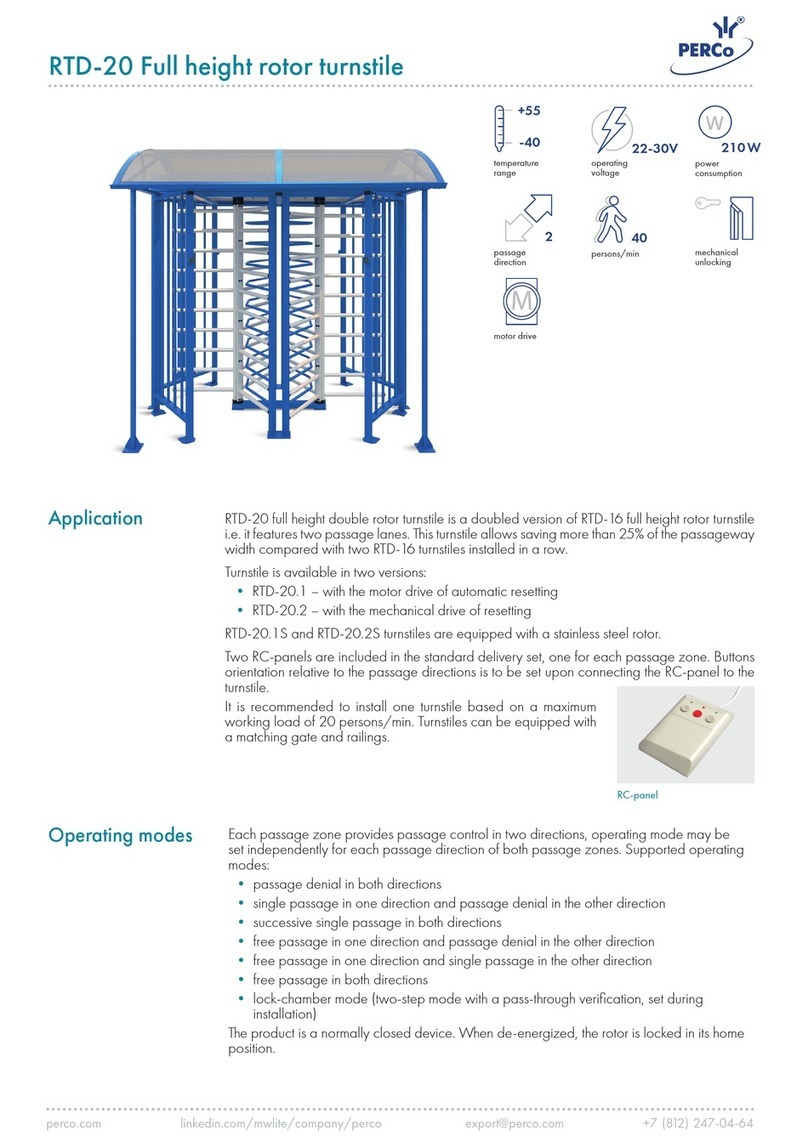
PERCo RTD-15 Series User manual

RF01 0-01
Certificate
Foundation frame
for full height rotor turnstiles
of RTD-15 series

Certificate
1.
1
GENERAL DATA
1.1 Foundation frame RF01 0-01 (hereinafter – the frame) is designed to ease in-
stallation as well as achieve quality and precision in installation of full-height turnstiles of
RTD-15 series, ensuring correct operation and reliability of the turnstile. It is recom-
mended to use the frame for outdoor application of the turnstiles.
1.2 Operation of the frame is allowed at ambient air temperature from – 40 to
+ 40°Сand relative air humidity of up to 98 % at 25°С.
1.3 The frame in the original package should be transported in closed freight con-
tainers or other closed type cargo transport units.
1.4 During storage and transportation the boxes can be stacked no more than 2
layers high.
1.5 Storage of the frame is allowed in dry indoor facilities at ambient air tempera-
ture from – 40 to + 45°Сand relative air humidity of up to 98 % at 25°С. The environ-
ment should be free of acid and alkali vapours and gases that cause corrosion.
1.6 After transportation or storage at temperatures below zero or at high air hu-
midity, prior to the installation the frame must be kept in the original package for 24
hours at least, under normal operation conditions (Ref. Clause 1.2).
2. TECHNICAL SPECIFICATIONS
Overall dimensions (L x W x H)..............................................................1792х1550х70 mm
Net weight:…................................................................................................................23 kg
3. STANDARD DELIVERY SET
–shell 1.....................................................................................................................1
–shell 2.....................................................................................................................1
–plate 1.....................................................................................................................1
–plate 2.....................................................................................................................2
–plate 3.....................................................................................................................1
–plate 4.....................................................................................................................1
Installation tools:
–bolt М8х20........................................................................................................... 12
–bolt М10х16......................................................................................................... 12
–bolt М10х50....................................................................................................... 12
–screw М16х60 .....................................................................................................1
–adjustment pin М8х120 ..........................................................................................8
–washer 8 (extended)............................................................................................ 12
–washer 10 (extended).......................................................................................... 12
–washer 10.......................................................................................................... 12
–washer 16 ............................................................................................................1
Technical documentation:
–certificate................................................................................................................1
–Package..................................................................................................................1
Used to fix a barrier section and a guide barrier section of the turnstile to the frame.
Used to fix a bottom bearing rotation unit of the turnstile to the frame.

Foundation frame RF01 0-01
4.
2
DESIGN
Design, overall view and overall and installation dimensions are shown in Figure 1.
The frame consists of 2 shells made of galvanized sheet steel, and connected with fix-
ture plates with one another.
Figure 1 – Overall and installation dimensions of the frame

Certificate
3
5. ASSEMBLY AND INSTALLATION
5.1 Installation details
It is recommended:
To perform works by at least 2 skilled workers;
To use installation tools:
– hex-nut wrenches S13, S17;
– level.
5.2 Assembly
Unpack the frame and check completeness of the delivery set as per Section 3. As-
sembly scheme is shown in Figure 2.
Figure 2 – Assembly scheme

Foundation frame RF01 0-01
4
5.3 Installation
Prepare foundation for the frame, sized 2000x1700 mm 200-250 mm deep, by
erecting shuttering on the perimeter, orienting it in accordance with layout of
your passage area; the bedding should be leveled, back-filled with gravel and
sand, and compacted;
Assemble the foundation frame in accordance with Figure 2;
It is recommended to horizontally and symmetrically fix reinforcement rods
600-700 mm long through holes in vertical walls of the shell 1 and shell 2;
Mount the assembled frame on the prepared foundation, oriented in accor-
dance with layout of your passage area; under adjustment pins put installation
supports minimum 50 mm thick (adjust position relatively to shuttering taking
into account concreting level);
Check horizontal alignment of the frame at turnstile fixing points, and if neces-
sary adjust it using gaskets and pins supplied in a standard delivery set; max-
imum allowable plane tolerance should not exceed 1,5 mm;
Using L-shaped installation pins and holes in shell 1 and shell 2 fix the frame
relatively to the foundation (installation pins are not included in standard deliv-
ery set); prior to casting the frame must be properly fixed against movements
in any direction;
Lay electric raceways in accordance with turnstile cables layout (Ref. Assem-
bly and Operation Manual of the turnstile) and passage area layout;
Fix the electric raceways relatively to the frame; ends of the electric raceways
should be above casting level (in plates 2 – the raceway is output through
holes designated for the indication cables; in plate 4 – the raceway is output
through the holes designated for control and power cables); it is recommended
to provide pulling wires to lay cables in the electric raceways in advance;
Outside the foundation frame the electric raceways are laid in accordance with
the passage area layout;
Pour concrete to the foundation using concrete of strength class of minimum
B22,5, up to the upper level of threaded bushes as shown in Figure 3.
Threaded holes of the frame (fixing points of the turnstile) should be blinded
with installation bolts to prevent concrete ingress into them during concreting.
NOTE!
Prior to concreting the threaded holes in the frame (fixing points
of the turnstile) must be blinded with installation bolts to pre-
vent ingress of concrete into them.
During concreting make sure all space of the foundation is filled with concrete,
including space under frame itself;
Time for the concrete to set-off before the turnstile mounting is determined by
climate conditions and concrete type.

Certificate
5
Figure 3 – Frame installation layout
6. PERCo WARRANTY
6.1 PERCo (the Manufacturer) warrants that the RF01 0-01 foundation frame (the
Product) complies with technical requirements provided that the instructions on stor-
age, installation and operation, given in the Certificate, are observed.
6.2 The warranty period is 24 (twenty four) months commencing from the date of
sale.
Should there be no date of sale on the warranty card, the warranty period shall
commence from the date of manufacture specified in the Certificate and on the Prod-
uct label.
6.3 In the post-warranty period the replacement parts/components are warranted
to be free from defects in material or workmanship for a period of 3 (three) months
from the date of shipment of the repaired/replaced Product to the Customer.
6.4 All claims with regard to quantity, completeness and defects to appearance
of the Product delivered are accepted by the Manufacturer in writing within no more
than 5 (five) working days after the products are received by the Customer. In case
of failure to meet the abovementioned deadline no claims are accepted.
6.5 The Warranty does not cover:
products, parts and components with:
- external mechanical damages resulting in the Product’s fault;
- defects resulting from Customer's improper testing, operation, installation,
maintenance, modification, alteration, or adjustment;
- damages due to force majeure circumstances (natural disasters, vandal-
ism etc.) or defects as a result of external circumstances (power surges,
electric discharge, etc);
fuses, accumulators, galvanic elements and other components, replacement of
which is performed by the Customer in accordance with the Product’s in-line do-
cumentation.
To the maximum extent permitted by the acting law, the Manufacturer does not in-
cur a liability for any direct or indirect losses of the Customer, including but not limited
to loss of profit or data, losses caused by idle period, missed profit, and etc related to

Foundation frame RF01 0-01
use or impossibility to use products and software, including possible software errors
and failures.
6
6.6 Within the warranty period the products are repaired free of charge at the Manu-
facturer’s site. The Manufacturer reserves the right to repair failed product or replace it
with an operational one. Time of repair is specified at the moment the Product is ac-
cepted for repair. Transportation cost to and back from the place of repair shall be
borne by the Customer.
In order to shorten the repair time the Customer must inform the Manufacturer’s
Technical Support Department (the TSD) of the problem with the Product’s operation
and/or about the origin of the fault by submitting a filled-in Technical Support Form by e-
mail, fax or via the Manufacturer’s website or communicate directly a specialist of the
TSD.
The Manufacturer reserves the right not to accept the Product for repair from the
Customer who failed to submit the Technical Support Form.
The Manufacturer’s warranty obligations don’t cover attendance by the experts of
a Customer and maintenance of any Product on site.
6.7 If in the course of the examination taken by the Manufacturer of the Product
or its parts/components believed to be faulty, no faults have been detected, the
Customer is responsible for compensation of the Manufacturer’s expenses related
to the examination.
6.8 Apart from the warranties mentioned above the Manufacturer does not pro-
vide any other warranties with regard to compatibility of a Product purchased with
software or products produced by other manufacturers as well as any warranties
that this Product will fit for the purposes not stipulated in the Product’s in-line do-
cumentation.
6.9 The warranty does not provide for any claims with regard to the technical speci-
fications of the Product in case they are in compliance with those stated by the Manu-
facturer. The Manufacturer does not guarantee that the Product purchased will meet
Customer’s requirements and expectations.
PLEASE NOTE THAT PERCo PRODUCES TECHNICALLY
SOPHISTICATED PRODUCTS THAT, IF NOT FAULTY, CANNOT BE
RETURNED BACK IF BY SOME REASON THE CUSTOMER DEEMS THEM
UNSATISFACTORY.

Certificate
7
WARRANTY CARD
Foundation frame RF01 0-01
for full height rotor turnstiles of RTD-15 series
Date of manufacture: « » ____________________201__
Quality Control Seal
______________________________
Date of sale: « » ____________________201__
____________________________________
(signature, seal)
Cutting line
Warranty Repair Coupon
Foundation frame RF01 0-01
for full height rotor turnstiles of RTD-15 series
Date of manufacture: « » ____________________201__
Quality Control Seal
______________________________
Date of sale: « » ____________________201__
____________________________________
(signature, seal)


PERCo Industrial
Tel.: +7 812 3216172, +7 812 3298924
Fax: +7 812 2923608
Legal address:
123-V ul. Leona Pozemskogo,
Pskov, 180600, Russia
www.percoweb.com

www.percoweb.com
Table of contents
Other PERCo Turnstile manuals

PERCo
PERCo TTD-12A Installation and operating instructions

PERCo
PERCo T-5 Installation and operating instructions

PERCo
PERCo TTR-08A Installation and operating instructions

PERCo
PERCo TTR-07.1 Installation and operating instructions

PERCo
PERCo Turnichetul TB 1 Supplement

PERCo
PERCo TTD-03.2 User manual

PERCo
PERCo TTR-10A Series Installation and operating instructions

PERCo
PERCo RTD-03S User manual

PERCo
PERCo TTR-11A Supplement

PERCo
PERCo ST-02 Series User manual