dlb AIJGO-22/COMP User manual

www.dlb.hu +36 27 502 555sales@destsa.hu
INSTRUCTION
MANUAL
AIJGO22/COMP
PERSONAL GROUNDING TESTER WITH PLATFORM,
DOUBLE DUAL FOOT ELECTRODE
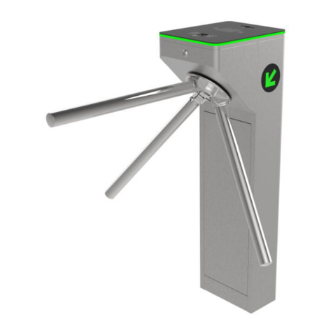
AND ENTRANCE GATE WITH TURNSTILE

TABLE OF CONTENTS
About the product ............................................ 3
Technical informations ........................................ 4
Parts of the tester ............................................. 5
Turnstile control system wiring guide .......................... 6
Items supplied with the tester ................................. 6
Assembly instructions ......................................... 7
Operation instructions .......................................10
Calibration instructions ....................................... 11

3
ABOUT THE PRODUCT
ӹTester for checking personal grounding before entering an ESD protected area
(EPA)
ӹTesting footwear system and wrist strap/groundable ESD smock system at the
same time
ӹCan be used to test a groundable ESD smock system
ӹTest result indication with LED light and sound
ӹSelectable test modes: Footwear sytem test only, or footwear system and wrist
strap/groundable ESD smock system combined test
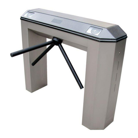
The AIJGO-22/COMP is an easy-to-use tester for checking personal grounding before
entering an ESD protected area (EPA). High load-bearing construction, it may be a
good choice if speed and security are important factors due to the large number of
entrances. Tester with LIGHT BAR system – such AIJGO products have a steel touch
button, the measured results are indicated by LED lights. COMPLEX type – these
testers are supplied built-in in an entrance gate with turnstile. The type of test can
be changed according to the entrance regulations: only footwear system test or
the combined test of the footwear system and wrist strap/groundable ESD smock
system. Thanks to the dual foot electrode, the tester simultaneously measures the
resistance of the right and left foot relative to the hand. In the event of a power
disconnection, the gate automatically drops down its turnstile to allow free passage.
The tester is supplied with manufacturer’s calibration certicate, platform, double
dual foot electrode,and entrance gate with turnstile.
CE declaration
We declare that the AIJGO-22/COMP product complies with the requirements of IEC
61340-5-1, ANSI/ESD S20.20 and Directive 2001/95/EC (General product safety).

4
Resistance values indicated as acceptable by the tester
Default setting when measuring footwear system 100 KΩ – 35 MΩ
An upper value of 100 MΩ can be set by short-circuiting both points of the tester’s TH2 spike pair. This
can be done using a jumper which is on one point of the tester’s TH2 spike pair. However, after setting a
dierent limit from the one used previously, the device must be restarted for the change to take eect.
Default setting when measuring wrist strap/
groundable ESD smock system 750 KΩ – 35 MΩ
TECHNICAL INFORMATIONS
AIJGO-22/COMP Personal grounding tester with platform, double dual foot electrode and
entrance gate with turnstile
AIJGO-BAR1 Barrier for AIJGO-22/COMP or AIJGO-34/COMP tester
AIJGO-LED/KI Optional door opening touch button outwards
Order codes
Gate properties
ӹManual rotation with mechanical assistance (rotary motor)
ӹRotation can be blocked electronically
ӹAutomatic turnstile drop down in the
event of power disconnection
ӹConnectable to a re alarm system,
it can be set to drop down the
turnstile after a signal from the
system, allowing free passage
through the gate.
ӹFor indoor use only
Test voltage 100 V DC
Wrist strap/groundable ESD smock system
connection
With a combined 10 mm snap, 4 mm banana
plug socket
Power supply 230 V AC
Sizes 1000 x 950 x 1049,5 mm with platform and touch
button

5
PARTS OF THE TESTER
1. Steel touch button with 9 RGB LEDs
2.
Combined 4 mm banana plug and 10 mm snap
socket for connecting wrist strap/groundable
ESD smock
3.
Switch for test type selection: if the upper
position is selected, the footwear system and
wrist strap/groundable ESD smock system are
tested, if the lower position is selected, only the
footwear system is tested
1
2
3
4
4. Cable for connecting foot electrodes
5
6
5. Connector to the common grounding point
of the gate
6.
Pair of TH2 spikes which can be used to set the upper resistance limit of the footwear system
measurement. After setting a dierent limit from the one used previously, the device must be restarted for
the change to take eect.

6
TURNSTILE CONTROL SYSTEM
Wiring guide
The tester is supplied built-in in an
entrance gate
Platform with foot electrodes, foot
electrode cables
ITEMS SUPPLIED WITH THE TESTER
Arm dropping (Input)
Crossing conrmation
(Output, Normally Open)
Crossing conrmation (Input)
Output direction start (Input)
Input direction start (Input)
LED ( - )
LED direction 1 (Output)
LED direction 2 (Output)
LED Common (Output)
Output latch control
(Output 24V 1A)
Input latch control
(Output 24V 1A)
Arm motor (Output)
12V DC 1A (Output)
Power, 24V DC 2A
Turnstile control system

7
ASSEMBLY INSTRUCTIONS
1. Place the platform to the desired location, then
remove the M8 screw nuts and washers (4-4
pieces)
2. Open the front cover of the gate with a key and
remove it from the gate
3. Place the gate on the platform (with the cables
of the foot electrodes routed through the
bottom of the gate)
4. Fix the gate to the platform using the screw
nuts and washers supplied
5. Connect the wires of the foot electrodes to be
used to the wires of the gate. Brown wire must
be connected to brown, blue to blue
6. Connect the wires of the unused foot electrodes
to the common grounding point of the gate

8
7.
If you want to set an upper resistance limit of
100 MΩ for measuring the footwear system,
cover both spikes of the tester’s TH2 spike pair
by short-circuiting them. To do this, you can use
the jumper which is on one point of the tester’s
TH2 spike pair. After setting a dierent limit
from the one used previously, the device must
be restarted for the change to take eect.
8.
Ask a qualied electrician to connect the
gate to the EPH network of the building. For
information on connecting the re alarm wiring,
see below.
Emergency open wiring guide
The connectors must be short-circuited and not energised, as this will cause the
panel to fail.
Turnstile control system
Emergency open (Input)

9
9. Turn on the circuit breaker
10. Put the front cover of the gate back in place and
lock it with a key
11.
If you have also purchased a barrier, unscrew
the 6 D-head M8 x 20 screws from the platform
and secure the barrier to the platform with
them
12. Remove the protecion foil from the foot
electrode plates
13. Connect the device to mains voltage
14. The tester is ready to use after the turnstile has
been folded up

10
OPERATION INSTRUCTIONS
1. Step with both feet on the middle of the foot
electrode plates
2. When testing a wrist strap/groundable ESD
smock, connect the wrist strap/groundable ESD
smock to the tester socket
3. Touch both halves of the steel touch button at
the same time and keep your hand on it while
testing is in progress
4. The tester gives light and sound signal about
the result
5. If the test results in acceptable values for the
tester, you can pass through the gate by turning
the turnstile forward

11
Interpreting the colour coding of the touch button
(WS: wrist strap/groundable ESD smock system, LF: footwear system – left foot
RF: footwear system – right foot):
CALIBRATION GUIDE
Foot electrode calibration
1. Place a measuring electrode on the foot
electrode you want to measure and connect it
to a resistance decade
2. Place a hand electrode on the right side of the
tester’s touch button and connect it to the
resistance decade
3. To calibrate, adjust the knobs on the resistance
decade
4. Start testing by touching both parts of the
touch button simultaneously
WS: OK
LF: OK
RF: OK
WS: FAIL
LF: OK
RF: OK
WS: OK
LF: FAIL
RF: OK
WS: OK
LF: OK
RF: FAIL
WS: FAIL
LF: FAIL
RF: FAIL
WS: OK
LF: FAIL
RF: FAIL
WS: FAIL
LF: OK
RF: FAIL
WS: FAIL
LF: FAIL
RF: OK

12
Wrist strap/groundable ESD smock connection calibration
1. Connect the wrist strap/groundable ESD smock
connection to a resistance decade
2. Place a hand electrode on the right side of the
tester’s touch button and connect it to the
resistance decade
3. To calibrate, adjust the knobs on the resistance
decade
4. Start testing by touching both parts of the
touch button simultaneously

13
Table to evaluate the results
The images in this document are for information only. We reserve the right to change the design, accessories,
technical specications and various details of the product without notice. In case of improper use other than
as described in this documentation or in case of modication of the product which D és Tsa. Bt. has not given
its written consent, our company may reject any warranty claims.
Calibration
parameters
Accepted maximum
deviation downwards
from expected value
Lower limit
value Expected value Upper limit
value
Accepted maximum
deviation upwards
from expected value
Footwear system test
(lower limit) - 20% 80 KΩ 100 KΩ 120 K Ω + 20%
Footwear system test
(upper limit) - 10% 31,5 MΩ 35 MΩ 38,5 MΩ + 10%
Wrist strap/groundable
ESD smock system test
(lower limit) - 20% 600 KΩ 750 KΩ 900 KΩ + 20%
Wrist strap/groundable
ESD smock system test
(upper limit) - 10% 31,5 MΩ 35 MΩ 38,5 MΩ + 10%

D és Tsa. Bt.
2600 Vác, Dr. Csányi László Krt. 83.
Hungary
Tel. / Fax: +36 27 502 555
+36 27 200 835
E-mail: sales@destsa.hu
Web: www.destsa.hu
www.dlb.hu
Table of contents
Other dlb Turnstile manuals
Popular Turnstile manuals by other brands

EMIT
EMIT SmartLog Pro 50723 Installation, operation and maintenance

Controlled Access
Controlled Access Tiffany T80-T Service & installation manual

Aventura
Aventura TS-FBS01 installation manual

Ier
Ier Automatic Systems PNG3 Series installation manual

Magnetic
Magnetic mTripod manual

LBA GROUP
LBA GROUP LBAT10 operating instructions