DM&P Group EBOX-335 DX3 Series User manual

EBOX-335xDX3SeriesMiniPC
User’s Guide

EBOX-335xDX3 Series User Manual
DMP Electronics Inc. 2
Copyright
This manual is subject to change without notice for continuous improvement in the product.
All rights are reserved. Manufacturer assumes no responsibility for any inaccuracies that may contain
in this document, and makes no commitment to update or to keep current information in this manual.
No part of this manual may be reproduced, copied, translated or transmitted, in whole or in part,
in any form or by any means without the prior written permission of the DMP Electronics Inc.
Copyright 2021 DMP Electronics Inc.
Trademarks Acknowledgment
is the registered trademarks of DMP Electronics Inc.
Other brand names, product names or trade names appearing in this document are the properties
and registered trademarks of their respective owners. All names mentioned herewith are served for
identification purpose only.
Safety Information
WARNING
Donot exposeEBOX torain or moisture,in order to prevent shockand fire hazard.
Never install EBOX in wet locations.
Do not open cabinet to avoid electrical shock. Referto the nearest dealer for qualified personnel servicing.
Never touch un-insulated terminals or wire unlesspower adaptor anddisplay monitor are disconnected.
Locate EBOX as close as possible to socket outline for easy access and to avoid force caused byentangling
of your arms with surrounding cablesfromthe EBOX.
When using EBOX, avoid using or installing themodem to the serialport during a storm or a lightning.
Do not use the modem or atelephone to report a gas leak in the vicinityof the leak.
USB connectorsaresupplied with Limited Power Sources.
DO NOT ATTEMPT TO OPEN OR TO DISASSEMBLE THE CHASSIS (ENCASING)
OF THIS PRODUCT. PLEASE CONTACT YOUR NEAREST DEALER
FOR SERVICING FROM QUALIFIED TECHNICIAN.

EBOX-335xDX3 Series User Manual
DMP Electronics Inc. 3
Regulatory
FCCClass A Note
This equipmenthas been tested and foundto comply with thelimitsfor a Class Adigital device,
pursuant to Part 15 of the FCC Rules. These limits are designed to provide reasonable protection against harmful
interference when equipment is operated in acommercial environment. This equipment generates, usesand
can radiate radio frequency energy and, if not installed and used in accordance with the instruction manual,
may cause harmful interference in which caseuser will be required to correct interference at his own expense.
Testing was done with shielded cables. FollowFCCregulations, user must use shielded cables with installation.
WARNING
This product complies withEN55032 class A. In a domesticenvironment, may cause radio interference
in which case the user may be required to take adequatemeasures.
Changesor modifications to this unit not expressly approved by the party responsible for compliance could void
the user’s authority to operate the equipment.
Thisdevice complies with Part 15 ofthe FCC rules. Operation is subjectto thefollowingtwo conditions:
(1) this device maynot cause harmful interference, and (2) this device must acceptany interference received,
includinginterference that may cause undesired operation.
This digital apparatus does not exceed Class A limitsfor radio noise emissions from digital apparatus as set out in
interference - causing equipment standard “Digital Apparatus”, ICES-003 ofthe Department of Communications.
Manufacturer’s Declaration of Conformity
This equipmenthasbeen tested and foundto comply with the requirements of European Community Council
Directives2014/30/EU & 2014/35/EU relatingto electromagnetic compatibilityand product safety respectively.
Attention
Thisproduct hasbeen designed and certified to comply with certain regulatoryrequirementspertaining to
Information Technology Equipment. This product hasnot been designed for use as a medical device.
Withoutlimitation ofthe foregoing,thisproductisnotintendedandhas not beencertifiedforuseina hospital
or clinical environment to diagnose, treat, or monitor patientsunder medical supervision, and is not intended
and has not been certified to make physicalorelectrical contact with patients, norto transfer energy to or from
patients and/or to detect such energy transfer to or from patients.

EBOX-335xDX3 Series User Manual
DMP Electronics Inc. 4
Purchase Agreement
Purpose:
In accordance to the general commercial conduct of Trust and FairTrade, herewith below is the agreement
for the protectionfor both parties, DMP and Users in pursuant of trading.
ProductDescription:
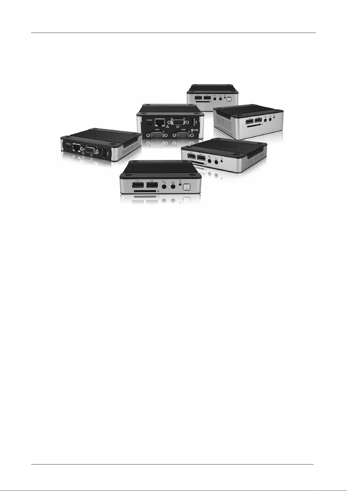
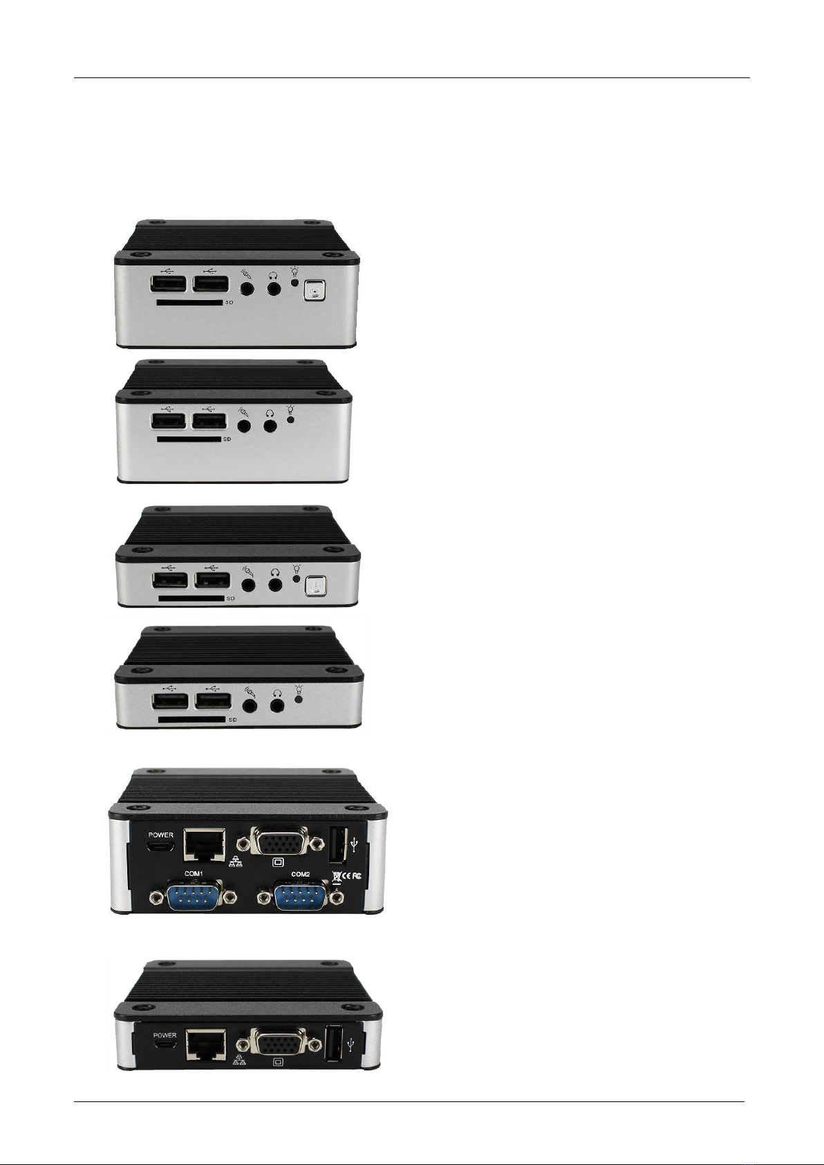
EBOX-335xDX3 Series is a simplifiedand economical design of an embedded device for Special Purpose PC.
It is comprised of x86 technology design withonboard 1GB/2GB DDR3 System memory, VGA or HDMI display,
USB, COM ports, and LAN Interfaces.
Distribution Convention:
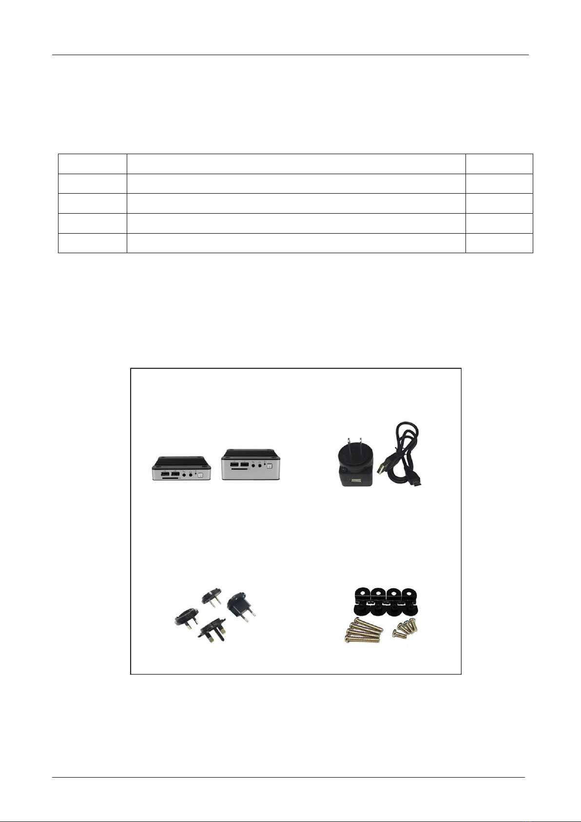
1. ThisProduct includesa PCanda power supply unit.Uponreceivingthisproduct, pleaserefertouser manual
to check for the contents and appearance of this product; contact the nearest dealer or DMP office
for any defective or missingpartsimmediately. Supplier will not be responsible foranyreported discrepancy
thereafterthe expiration period of 3-days from the received date.
2. In consideration of transportation and thecost of storage,the supplier provides to thedistributors
a warranty of 12 months. This warranty covers the failure caused by hardware breakdown
(excluding hard drives), butdoes not cover the act of misuse and mishandling.
3. The supplier will not accept unknown post, therefore if you wish to repair or to return your goods,
please contact your nearest dealer to make your declaration, at thesame time, apply for an RMA number
(RMA stands for Return Merchandise Authorization), ask for RMA form andfill-up for authorization.
4. Thefreight forreturn goods for repair willfollow the International customary practice and convention.
Both parties istopay for freight of one shipment each. The shipper is required toprepay the freight from
the place of origin (This means that thereturnee/user covers the freight for return goods, while theSupplier
covers thefreight for goods after the repair).
5. Obsolete warrantyis referred to as: (1) Expiration of warranty or (2)Damage due to misuse within warranty.
TheSupplier will be taken into consideration of the circumstances,to provide repair service with charges
expensefor obsolete warranty. This expense includes the cost of material andthe cost of labor.
Note: If there is other particular issue, not listed in theabove conditions, both parties agreed to follow
General Law of Commerce with fair and reasonablediscussion in handling andresolving the argument.

EBOX-335xDX3 Series User Manual
DMP Electronics Inc. 5
Contents
Chapter 1
07 UnpackingEBOX MiniPC
Chapter 2
10 EBOX-335xDX3 SeriesOverview
11 EBOX-335xDX3-RCASeries Overview
12 SystemSpecifications
13 SD card recommendation
Chapter 3
15 BIOS Reconfiguring
16 Drivers Installation Guide
19 Additional Information
19 Screen rotation
20 Turn off the display function setting
21 HDMI 1080p video playback
22 PXE Diskless boot setting
23 Linux installation
Chapter 4
29 Onboard Connectors Summary
30 Pin Assignments
Chapter 5
33 TakingCare ofEBOX
35 Troubleshooting
Chapter 6
38 TermsandCondition
38 Warranty
38 Serviceand Support
38 Return MerchandiseAuthorization (RMA) Policy
38 ShippingPolicy

EBOX-335xDX3 Series User Manual
DMP Electronics Inc. 6
Chapter1

EBOX-335xDX3 Series User Manual
DMP Electronics Inc. 7
Unpacking EBOX Mini PC
Component List:
ItemNo.
Description
Quantity
1
EBOX-335xDX3 Series MiniPC
x1
2
Power supply 10W; Vin: 100~240V AC 50~60Hz + USBtoMICRO USB cable
x1
3
Power plug (available US, UK, EU, AU types)
x1
4
75 x 75mm to 100 x100mm VESA mountingrack (Optional)
x4
Note: The accessories are subject to change without immediate notice.
Check before Use
1. EBOX-335xDX3 Series Unit
2. Power adapter 10W
3. Switchable Power plug
4. VESA rack (Optional)

EBOX-335xDX3 Series User Manual
DMP Electronics Inc. 8
Preface
EBOX-335xDX3 Series Mini PC
EBOX-335xDX3 Series is a revolutionary device especially designed for limited space andtemperature concerns.
No matteryou arein ajammedoffice,a crowded place, or publictransportation,EBOX can be easily integrated
with a VESA LCD to bring it to access at any time.
It can be attached to any VESA mounting fixture; allowing to be securely mounted onto desks, walls, or buildings,
and therebyoptimizesyourwork area. It can also attach toany size LCD for a mobile system for trade shows,
presentations, promotions,etc. It’s ideal to be usedin the environment where temperature demand is critical.
If you’re looking for a device that isable to provide with more mobility, less power consumption at the same time,
EBOX-335xDX3 Series will be surely meet your need.
The VESA® FDMI™ Standard defines mounting interfaces, hole patterns and associated cable/power supply
locationsfor LCD monitors, plasma displays andother flat panel devices.EBOX-335xDX3Series isdesigned
tofitthisstandardtomakemonitor attachmentquickly andeasily.

EBOX-335xDX3 Series User Manual
DMP Electronics Inc. 9
Chapter2

EBOX-335xDX3 Series User Manual
DMP Electronics Inc. 10
EBOX-335xDX3 Series Overview
Front Panel
A: Reset Button
System reset or turn on use
B: LED indicator
Blue LED light indicates system power
Red LED light indicates SD card activation
C: Audio Line Out
Audio output
D: Audio Mic In
Microphone input
E: USB 2.0 ports
External USB devices use
F: SD Card Slot
SD Card use, support system bootable from SD Card
Back Panel
G: USB 2.0 ports
External USB devices
H: VGA port D-Sub 15-pin
VGA display output
I: RJ-45 LAN Jack
10/100 Mbps LAN x1 (Built-in PXE diskless boot)
or 1G LAN x1 (PXE not support)
J: Micro-B USB Power connector
K: COM ports
RS-232 x2
G
H
G
I
J
K
K
A
B
C
D
E
F
B
C
D
E
E
F
E
G
H
G
I
J
*Model with Auto Power On features
do not have reset button.
B
C
D
E
F
E
A
B
C
D
E
F
E

EBOX-335xDX3 Series User Manual
DMP Electronics Inc. 11
EBOX-335xDX3 RCA Series Overview
Front Panel
A: Micro SD Card Slot
System support bootable from Micro SD Card
B: Audio Mic in
Microphone input
C: Audio Line Out
Audio output to speaker
D: Power LED
LED lights up when system is turned on
E: Internet LED
LED lights up when system is connected to internet
F: USB 2.0 ports
External USB devices use
Back Panel
F: USB 2.0 ports
External USB devices use
G: RJ-45 LAN Jack
10/100Mbps LAN built-in PXE diskless boot.
H: HDMI output
HDMI display output
I: Power switch
To turn the system power on or off
J: Micro-B USB Power connector
K: RCA jack (Isolation)
Support speaker with RCA input
L: VGA port D-Sub 15-pin
VGA display output
F
G
G
H
J
K
A
B
C
D
E
F
I
L
F
G
J
K
F

EBOX-335xDX3 Series User Manual
DMP Electronics Inc. 12
System Specifications
CPU
Vortex86DX3 Dual core (1GHz)
*Windowsplatform 64-bit not support
Main Memory
1GB DDR3 (32-bit DRAM bus, EBOX-3350DX3 Series)
2GB DDR3 (32-bit DRAM bus, EBOX-3352DX3 Series)
BIOS
AMI BIOS
Display
VGA: Resolution up to 1920 x 1080 pixels
HDMI: Resolution up to 1920 x 1080pixels
I/OConnectors
1. USB2.0 x3
2. SATAx1 (SATA DOM only)
3. SD Card slotx1
4. MicroSD card slot x1
5. 10/100MbpsLAN x1 or 1GLANx1
6. Micinx1+Lineout x1
7. StandardMini PCIe x1(not support USBSignal)
8. RS-232 port x2
9. RCA connector x2
Dimension & Weight
95 x 95 x 20mm/280g
95 x 95 x 35mm/360g
Powerconsumption
EBOX-335xDX3 Series: DC +5V/2A
EBOX-335xDX3-RCA Series: DC +5V/1.5A
Supported Operating system
Windows 7 Home/Pro
Windows 7 Embedded
Windows XP Home/Pro
Windows XP Embedded
Linux OS (Support list on EBOX website)
*Click OS support list for more details.

EBOX-335xDX3 Series User Manual
DMP Electronics Inc. 13
SD/ Micro SD card recommendation
To use Class 10 SD card is highly recommended.
EBOX-335xDX3 Series support SD and SDHC only (SDXC not support). Users may use SDXC on EBOX,
however, it will be recognized as SDHC and capacity support up to 32GB only.
Test environment:
Products: EBOX-335xDX3 Series
SD card: Kingston Canvas Select SDXC UHS-I 64GB Class 10
BIOS: AMI BIOS
OS: WES7 (Windows embedded standard 7)
Disk benchmark software: CrystalDiskMark 6.0.2
Test result:
SD card Speed
Read [MB/s]
Write [MB/s]
Seq Q32T1
21.34
15.39
Note: Seq Q32T1: Sequential (Block Size=128KiB) Read/ Write with multi Queues & Threads

EBOX-335xDX3 Series User Manual
DMP Electronics Inc. 14
Chapter3

EBOX-335xDX3 Series User Manual
DMP Electronics Inc. 15
BIOS Reconfiguring
1. To reconfigure the hardware, press the <Del> key to enter the BIOS setup main menu as below:
2. Press <Esc> to go back to main menu.
3. Press <F9> to load factory default setting.
4. Adjust BIOS settings, and be sure that your settings will affect.
For Windows platform users, please use default setting directly.
5. Press <Tab> move to boot menu to find default setting as below:
6. Set up the boot device order, press <F10> and select “Save Settings and Exit”,
press “Y” to save the changes. Unit will restart to the new setup.

EBOX-335xDX3 Series User Manual
DMP Electronics Inc. 16
Drivers Installation guide
Underthe Windows series OS, the following drivers need to be installed manually.
1. M2015R7 VGAdriver
2. Ethernetdriver
3. USBWirelessLAN Dongledriver(Optional)
4. Audio driver (for windows XP only)
Note:
1. Please download drivers from EBOX website.
2. For Windows 7orWindows 7 Embedded OS, install XMPlay for audio player, download here.
VGAdriver:
Unzipthe downloaded file and double clickthe setting .exe file then “Next” as below to install:
AfterVGA driverinstalled, restart computerand you will beable to select resolution up to 1920 x1080pixels.

EBOX-335xDX3 Series User Manual
DMP Electronics Inc. 17
Ethernet driver:
1. Find the yellowquestion mark of Ethernet in the Device Manager under the control panel/ system.
2. Select “Update Driver Software” and choose the right path, then click “Install this driver software anyway”
when Windows Security popped out.
3. Afterinstallation completed, theDevice Manager will update and show the correct device.

EBOX-335xDX3 Series User Manual
DMP Electronics Inc. 18
Audio driver:
Unzip the downloaded file and double click the setting .exe file, then “Next” as below to install.
Afterthe installation completed, the Device Manager will update and show the correct device.

EBOX-335xDX3 Series User Manual
DMP Electronics Inc. 19
Additional information
Screen rotation:
1. After VGA driver installation completed, type “Customize icons” in search bar.
2. Adjust Utility Application to “Show icon and notifications”.
3. A blue icon = Graphic Utility appears on screen, double click it.
4. In Graphic Utility, go to Rotation section. Select the direction of rotation then press Apply to test
and OK to save the changes.

EBOX-335xDX3 Series User Manual
DMP Electronics Inc. 20
Turn off thedisplay function setting:
For Win 7 or Win 7 Embedded OS users, click Start Menu > Control Panel > PowerOptions
or simply search for "Power Options" (without quotes). You will see a list of different power plans.
Theplan currently in usehas ablue dot in front of it. Click "ChangePlanSettings"next to thepowerplan.
Click on the drop-down menulist which is exactlynext to "Turn off thedisplay".
Fromthe options, youcansetthe amount of idletime.
EBOX-335xDX3 Series does not support sleep function, it cannot wake up after sleep.
To avoid the unwakeable situation, disable the function by setting “Put the computer to sleep” to “Never”.
This manual suits for next models
1
Table of contents
Other DM&P Group Desktop manuals