Dnepr MT10-36 User manual

Due
to
continuous
development
of
the
produ
ct
aimed
at
the
improvement
of
its reliability
and
operating
con
-
diti
ons
there
may_
be
some n
eglig
ible dis
crepan
cies
bet-
we
en the
product
design
and
it
s d
es
cri
ption
in this
pub
-
l
icat
i
on
. •
To
the
Customer
's
Notice
Check
the
comp
let
eness
of
the
motorcycle
set.
Each
motorcycle
is
sold
complete
with:
I.
Certificate.
2.
Operating
Ins
tructions.
3. Brief
In
structions
on the Use of
Storage
Batteries.
4. Tool Kit.
5.
Spare
Pads
Kit
._
.
Due to
the
constant·
..
9evelopm~nt
of
the
motorcycle
design
some
minor
modifications
not
indicated
in
this
manua
l
can
be
expected in the
purchased
machine.
Before
star
ting
motorcycle oper
ation
do
not
fail to
fill
the
air
cleaner
bath
with 150
cm3
of oil.
To
avoid
burning
thro
ugh
of
the
silencer in c
ase
of
the
engine
operation
on
too rich
mixture
and
with
late
ignition
advance
angle,
care
should
be
taken
to c
orrectly
adjust
the
carburattor
and
to
set
the
ignition
advance
angle
(see
"A
djus
ting
the
Carburettor"
and
"Ignition
Ti-
ming").
.
··
·

r~
A
1'-1
.1
-
~A.V"'
;../1'<-is
4c
s·
<LI
r-
L
A~~
'f3
F 5
..-"7~
-z..
7
j'
6~
:;,
c..
J...
1.-J
..8
L5
c..
~d=r~~
41£
v·
-z_
.A/
G
;-<
1J
,Os-
!i
5
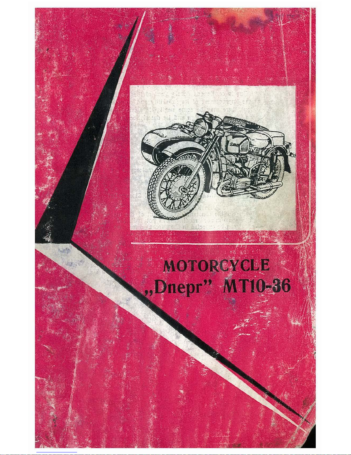
MOTORCYCLE
"
Dnepr"
MTI0-36
OP
ERATING IN
STRUCTIONS
VfO
AV
TOEX
PO
RT e USSR 0 MO
SC
OW
CONTENTS
Int
roduction
Specifications . . .
Controls
and
Instruments .
Pre
paring a Motorcycle for Use
Ope
rating
Instru
ctions . . . . . . . . . .
Driving
Pro
cedure . . . . . . . . . . .
Design, Operation and Adjustment of Motorcycle B
11sic
Units
Tr
oub
le
shooting . . . . . . . . . . . .
Technical Servicing
Stor
age
. . . . .
Bearings Used in Motorcycle .
Rubber Collars Used
in
Motorcycle
P
age
3
5
7
11
12
14
1!1
81
85
89
89
93
8004

INTRODUCTION
The "
Dnepr
" motorcycle model
MTl0-36
is a
roadster-type
hea-
vy-class
vehide
designed for
operation
with
a
sidecar.
T·he
general
view
of
the
motorcycle is
given
in
Fig.
1.
Fig.
1.
Motorcycle "Dnepr" MTI0-36
This
manual
is the
main
guide
for c
arrying
out
correct
mainte-
nance
a
nd
operation
of
the
MTl0-36
motor
cycle.
It
states,
though
briefly
but
rather
clear, the
main
motorcycle s
pe
cifications, its de-
sign,
and
principle of
operation
of
its
basic
units
and
mechanisms.
The
m
anua
l .
iists
the
necessary
data
on
troubleshooting.
The
terms
and
scope
of
the
motorcycle
mainten
ance
ope
rations
are
given
ta-
king
into
account t
he
.peculiarities of its
operation
as
well
as
the
storage
ru
les between
the
operati
ng
periods.
It
should
be
borne
in
mind
t
ha
t ne
li
able
and
tro
ublefree
operation
of
the
motorcycle depend
first
of all
on
str
ict
adheren
ce
to
there-
quirements
set
forth in these
Operating
Instructions.
The
book
·
c~mtains
the
following
basic
sections:
3
Table of contents
Other Dnepr Motorcycle manuals

Popular Motorcycle manuals by other brands

MV Agusta
MV Agusta Brutale 675 Workshop manual

APRILIA
APRILIA RSV MILLE - PART 1 1999 User manual content

Royal Enfield
Royal Enfield Himalayan 2018 owner's manual

SSR Motorsports
SSR Motorsports Lazer5 owner's manual

MOTO GUZZI
MOTO GUZZI 2005 Griso 1100 Use and maintenance book

KTM
KTM 85 SX 19/16 owner's manual


