DNH DHVC5000 Series Mounting instructions

DHVC5000 Series MVC
USE’S MANUAL

Prior to use,please read this user’s manual carefully.
CAUTION:Please keep this user’s manual for future reference.

DHVC500 Series MVC
USER’S MANUAL
English Version V1.1
Jiaxing DNH Electronic Science&Technology Co.,Ltd

1
Thanks for using the product
Please read the manual carefully before using(install, operation, maintenance, checking) the
product.
The manual is used for routine maintenance and check as well as the analysis of abnormal
phenomenon.
MVC operation manual, version No.:V1.0.0

2
Content
Thanks for using the product.........................................................................................................1
Chapter 1 Human-Machine Interface...........................................................................................4
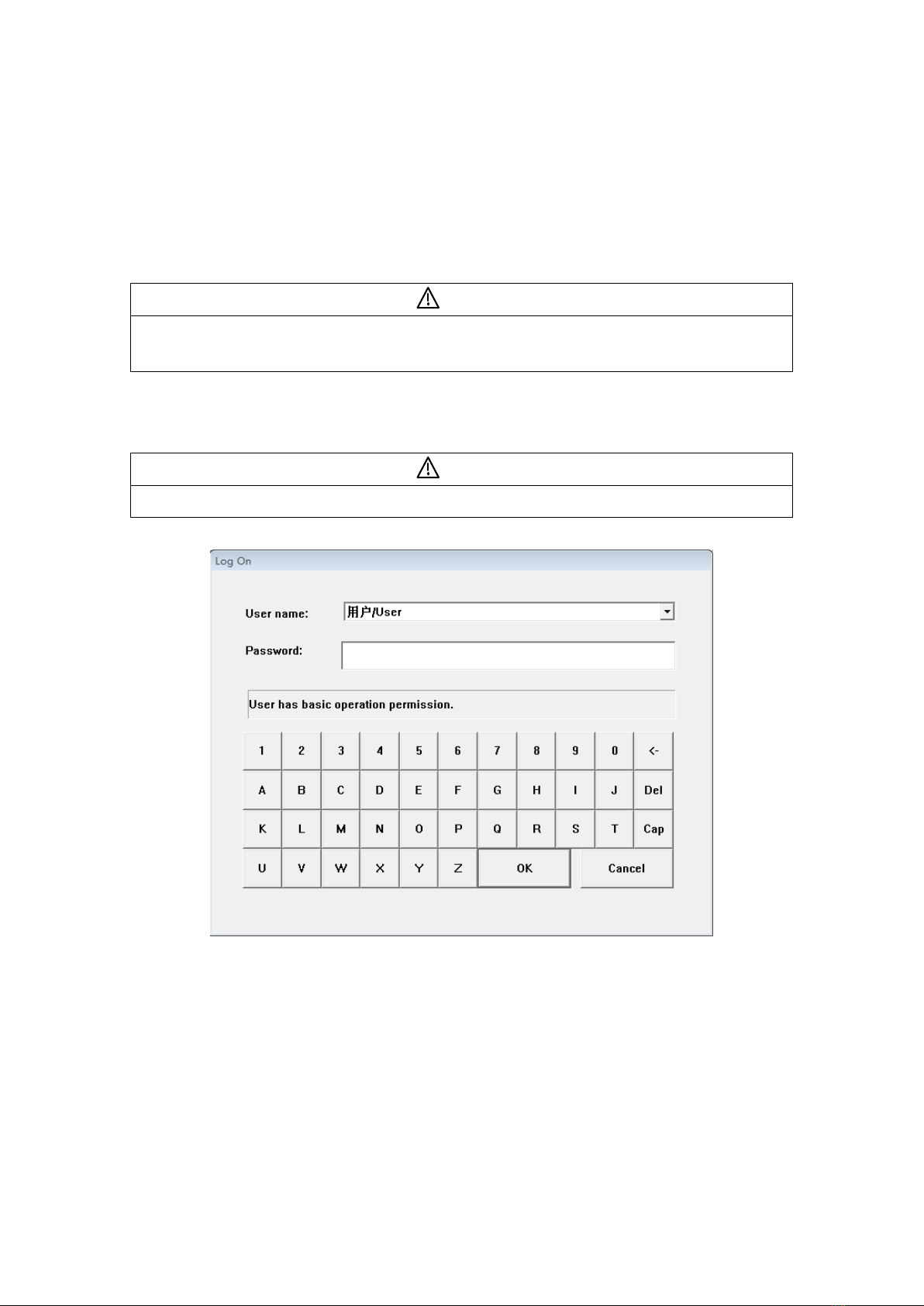
1.1 Log-In.....................................................................................................................................4
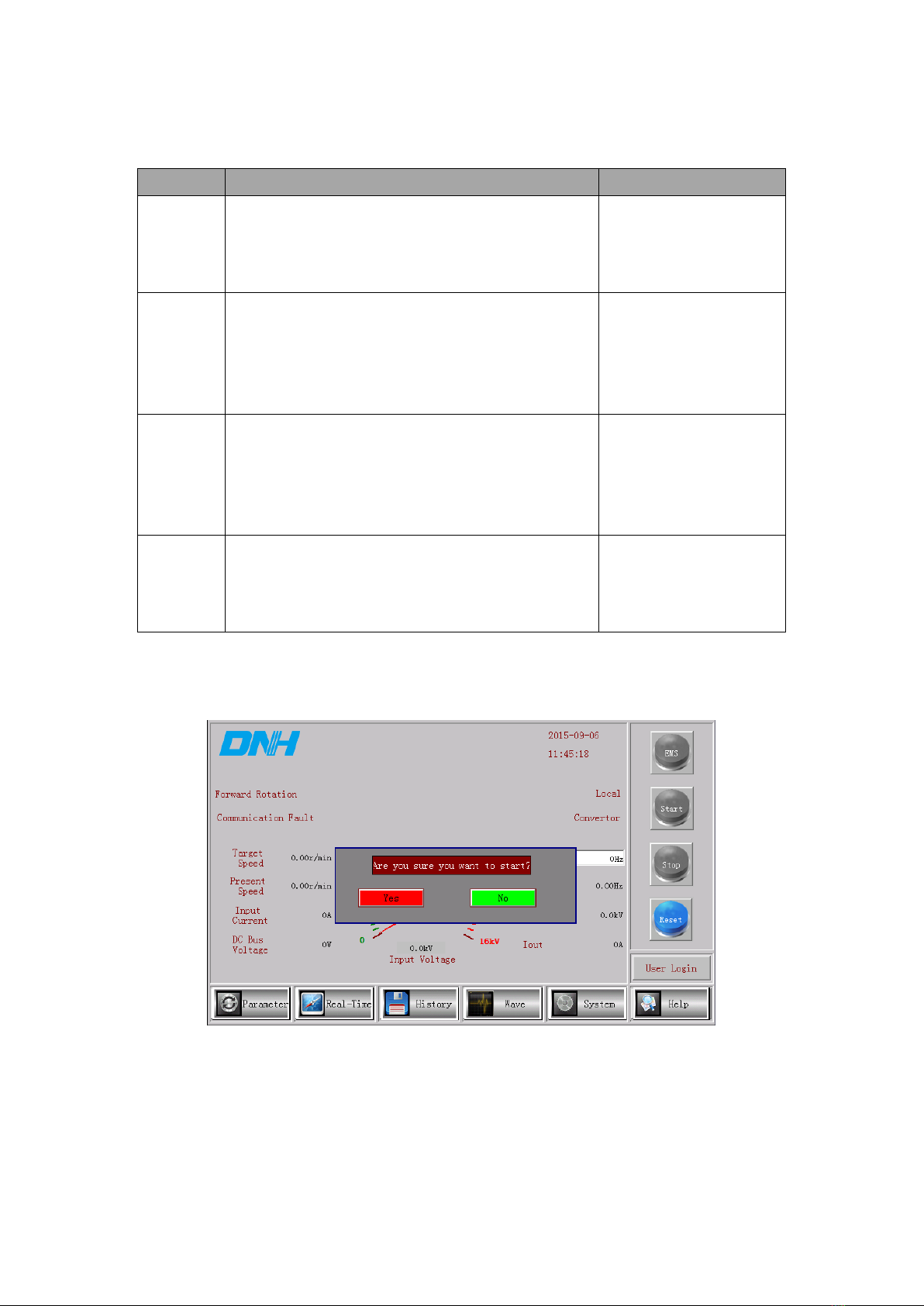
1.2 Main Screen...........................................................................................................................5
1.2.1 Control Button Area .........................................................................................................5
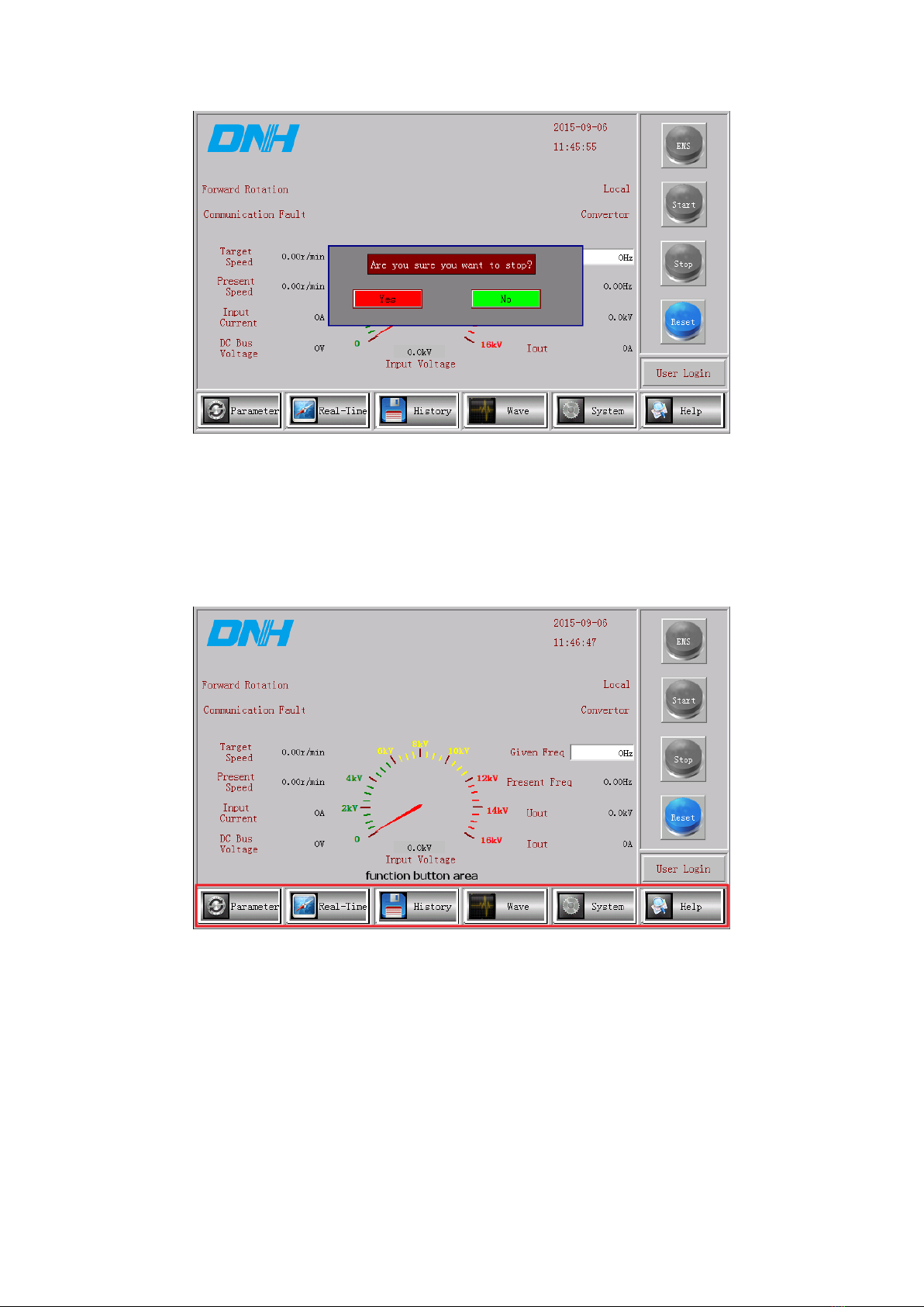
1.2.2 Function Button Area .......................................................................................................7
1.2.3 State Display Area............................................................................................................7
1.3 Parameter Setup Screen .......................................................................................................9
1.3.1 Speed Regulation Parameters...........................................................................................9
1.3.2 Control Parameters.........................................................................................................12
1.3.3 vector Parameters...........................................................................................................13
1.3.4 Motor Parameters...........................................................................................................15
1.3.5 Communication Parameters ...........................................................................................15
1.3.6 Sensor/Measurement Range...........................................................................................16
1.4 Real Time Data Screen .......................................................................................................16
1.4.1 System State...................................................................................................................17
1.4.2 Inverter Unit State..........................................................................................................18
1.4.3 Digital Port State............................................................................................................19
1.4.4 Analog Port State............................................................................................................20
1.4.5 Data State .......................................................................................................................21
1.4.6 Synchronoscope .............................................................................................................21
1.5 Historical Data Screen ........................................................................................................22
1.5.1 Fault History ..................................................................................................................22
1.5.2 Alarm History.................................................................................................................23
1.5.3 Operating Record ...........................................................................................................24
1.5.4 Runtime Log ..................................................................................................................24
1.6 Waveform Display Screen ..................................................................................................25
1.6.1 Instantaneous Curve.......................................................................................................25
1.6.2 Running Curve ...............................................................................................................26
1.6.3 Fault Record...................................................................................................................27
1.7 Help Screen..........................................................................................................................28
Chapter 2 Trial Run......................................................................................................................31
2.1 Trial Run Steps ....................................................................................................................31

3
2.1.1 Check And Screw Fastenings.........................................................................................31
2.1.2 Connect Control Power Supply......................................................................................31
2.1.3 Display Confirmation of State........................................................................................31
2.1.4 Basic Parameter Settings................................................................................................32
2.1.5 Control Mode Selection .................................................................................................32
2.1.6 Main Circuit Power Supply Connection ........................................................................33
2.2 MVC Start Process........................................................................................................33
2.2.1 Application Settings .......................................................................................................33
2.2.2 No-Load Operation ........................................................................................................34
2.2.3 Connection of Load Machine.........................................................................................34
2.2.4 Actual Load Operation ...................................................................................................34
2.2.5 Local Operation..............................................................................................................34
2.2.6 Operating State Confirmation ........................................................................................34
2.2.7 Confirm And Save Parameter Settings...........................................................................34
Chapter 3 Common parameter.................................................................................................35
3.1 Parameter List..................................................................................................................35
3.2 Parameter Description List ................................................................................................35
3.3 Parameter List..................................................................................................................36
3.3.1 Speed Control Parameters ...........................................................................................36
3.3.2 Motor parameter.............................................................................................................37
Chapter 4 Fault Diagnosis............................................................................................................39
4.1 Fault Query..........................................................................................................................39
4.2 Troubleshooting...................................................................................................................39
4.3 Causes of Faults, Alarms And Their Remedies ................................................................39
4.4 User Side Faults.............................................................................................................42
4.4.1 User Power Supply Problems......................................................................................42
4.4.2 Incorrect Operation By The User................................................................................42
4.4.3 User Environmental Factors........................................................................................42

4
1 Chapter 1 Human-Machine Interface
DHVC HMI adopts MCGS configuration software, which is used for the communication
with the control system to realize the visual display system, so that the user may monitor operating
conditions and failure alarms more intuitively. The monitoring system uses HMI which has a clear
view of the MVC parameters, fault records etc.
Attention
The touch screen may only be used by the user to monitor the MVC operating state, accessing the system
setup or changing the system parameters is forbidden without the authorization of RXPE.
1.1 Log-In
User Log-In window is shown in Fig.1-1. User name is - User, password is - RXPE.
Attention
It is forbidden to use the name of any other user to log-in to the system without the authorization of RXPE.
Fig.1-1 User Log-In Window

5
1.2 Main Screen
The Main Screen is shown in Fig.1-2:
Fig.1-2 Main Screen
The main screen has four parts: a control button area, state display area, function button area
and user log-in button.
1.2.1 Control Button Area
The control button area is located on the right side of main screen, including the control
buttons for reset, stop, start and one button for emergency stop. As shown in Fig.1-3:
Fig.1-3 Control Button Area
For the function of each button, see Table 1-1.

6
Table 1-1 Control Buttons and Their Functions
Button
Function
Color
Reset
Control Button
Clear MVC fault, charge the MVC, meet ready state
Blue, reset button may be
used
Gray, reset button may not be
used
Start
Control Button
After the MVC is ready, click ‘Start’ button, a dialog box will
pop up, select ‘Yes’ to start the MVC, select ‘No’ to cancel the
start of MVC. The start pop-up box is shown in Fig.1-4.
Green, start button may be
used
Gray, start button may not be
used
Stop
Control Button
After the MVC is put into operation, click ‘Stop’ button, a
dialog box will pop up, select ‘Yes’ to stop the MVC, select
‘No’ to cancel stopping the MVC. The start pop-up box is
shown in Fig.4-2.
Yellow, stop button may be
used
Gray, stop button may not be
used
Emergency
stop
Display Button
Displays the state of the emergency stop button on MVC
control cabinet door
Red, MVC is in emergency
stop state
Gray, MVC is in
non-emergency stop state
The start dialog box shown in Fig.1-4 will pop up if you click the start button, when
everything is ready, if you want to start the MVC ,please click Yes, else please click No.
Fig.1-4 Start Button Pop-Up Box
The dialog box shown in Fig.4-5 will pop up if you click the stop button. If you want to stop
the MVC ,please click Yes, else please click No.

7
Fig.1-5 Stop Button Pop-Up Box
1.2.2 Function Button Area
The function button area is located at the bottom of the main screen and includes six function
buttons: Parameter (Parameter Settings); Real-Time (Real Time-Data); History (Historical Data);
Wave (Waveform Display); System (System Configuration) and Help. As shown in Fig.1-6:
Fig.1-6 Function Buttons
Click the relevant button to enter the corresponding function menu.
1.2.3 State Display Area
The State Display Area is shown in Fig.1-7: the state display area shows the current state of
the MVC including Current Time, Communication State of touch screen and
controller,Local/Remote Mode, MVC and the load Operational Data, MVC and the load control
State.

8
Fig.1-7 State Display Area
The time display column displays the current time.
The MVC ‘Given Freq’ value may be set (effective only during local control) by clicking the
‘Given Freq’ value text, the frequency setup popup box will open allowing the frequency value to
be entered as required, this will take effect immediately after clicking the’Ok’ button. The
parameter setup range is 0-50Hz. As shown in Fig.1-8:
Fig.1-8 Setpoint Frequency Pop-Up Box
Present Speed column displays current MVC operating frequency.
The Uout column displays current MVC average three-phase output voltage.
The Iout column displays current MVC average three-phase output current.
The Input Current column displays current MVC average three-phase input current.
The DC Bus Voltage column displays current MVC average three-phase bus voltage.
The Present Freq column displays operating speed of current MVC load.

9
The Given Freq column displays the given speed of current MVC load.
1.3 Parameter Setup Screen
Click the ‘Parameter Settings’ button on the Main Screen to enter the Parameter Setup Screen.
Click the top left button to set the MVC speed regulation parameters,control parameters, vector
parameters, motor parameters, communication parameters and sensor parameters. Click the ‘Main
Menu’ button to return to the Main Screen, thereinto, the access authority of speed regulation
parameters,vector parameter, motor parameter, communication parameter, sensor parameter are
granted to: the commissioning personnel, administrator; the access authority of control parameter
is granted to :operator, commissioning personnel, administrator.
1.3.1 Speed Regulation Parameters
Click the ‘Speed Regulation Parameters’ button on the Parameter Setup Screen to set the
MVC speed regulation parameters, as shown in Fig.1-9. Click Page Down and Page Up to flip
over in the speed regulation parameter screen。Fig.1-9 shows the speed up/down setting in speed
regulation parameters. Acceleration, Deceleration and transition frequency may be changed to
realize the frequency speed regulation function.
Acceleration1:the time from 0Hz to transition frequency 1;
Acceleration2:the time from transition frequency 1 to transition frequency 2;
Acceleration3:the time from transition frequency 2 to highest frequency;
Deceleration1:the time from transition frequency 1 to 0Hz;
Deceleration2:the time from transition frequency 2 to transition frequency 1;
Deceleration3:the time from highest frequency to transition frequency 2;
Fig.1-9 Speed Increase/Decrease Setting
Click the dialog box of the parameter to be set on the touch screen, a data input dialog box
will pop up, as shown in Fig.1-10:

10
Fig.1-10 data input dialog box
Fig.1-11 Shows the frequency skipping settings in the speed regulation parameters. The
frequency skipping upper limit, frequency skipping lower limit, minimum frequency and
maximum frequency may be changed for a smooth transition of the variable frequency speed
regulation system at resonance point. When frequency skipping is disabled,running the motor and
observe its running state. If motor appears large oscillation at one certain frequency,then record
the current frequency. Set frequency skipping point of upper limit and lower limit, enable the
motor won’t run at the frequency of large oscillation.
Fig.1-11 Frequency Hopping Setting
Fig.1-12 shows the V/F curve settings in the speed regulation parameters (In this example the
control mode is V/F).

11
Fig.1-12 V/F Curve Setting
When the MVC control mode is vector control, the V/F curve settings in the speed regulation
parameters is shown in Fig.1-13:
Fig.1-13 Vector V/F Curve Setting
Fig.1-14 Shows the flying control setting and process PID closed loop settings in speed
regulation parameters.
MVC with flying start function,once received start command again,search the inertia speed of
the motor,and start motor at the inertia speed frequency,which will reduce delay and impact.
MVC process PID closed loop function may enable MVC to achieve external closed loop
adjustment for one certain control subject.

12
Fig.1-14 Flying and PID setting
1.3.2 Control Parameters
Click the ‘Control’ button on the Parameter Setup Screen to set the MVC control parameters,
as shown in Fig.1-15:
Fig.1-15 Control Parameter Window
Click the ‘Motor Direction’ and then select ‘Forward’, and then motor will forward running’; on
the contrary, if you select ‘Reverse’, motor will reverse running.
Click‘control mode’,and select ‘local’,then control MVC relevant operation by touch screen;
select‘remote’, then control MVC relevant operation by remote operation machine.
Click closed loop preset mode,select‘local’,then the closed loop preset value may be set by
touch screen; select‘communication’,then the closed loop preset value may be set by MODBUS
communication; select‘analog’, then the closed loop preset value may be set by external 4-20mA
analog signal.
Click remote mode,select‘digital’,then MVC start,stop command may be controlled by
external digital signal;select‘communication’, then MVC start,stop command may be controlled

13
by MODBUS communication.
Click remote frequency preset mode,select‘analog’,frequency preset may be set by external
4-20mA analog signal;select‘communication’, frequency preset may be set by MODBUS
communication.
Click working mode,select‘converter’,then the motor running may be controlled by MVC;
select‘grid’,motor running by grid connection. Thereinto,the function may be switched automatic
after grid connection. It is required 50Hz for motor running when grid connection.
1.3.3 Vector Parameters
Click the ‘Vector Parameters’ button on the Parameter Setup Screen to set the MVC vector
parameters, Click Page Down and Page Up to flip over in each screen. When the MVC load is a
asynchronous motor, the vector parameters are shown in Fig.1-16 and Fig.1-17:
Fig.1-16 Asynchronous Motor Vector Parameter Window (1)
Fig.1-17 Asynchronous Motor Vector Parameters Window (2)
As an example, when the MVC load is a synchronous motor, the vector parameters are shown

14
in Fig.1-18 and Fig.1-19:
Fig.1-18Synchronous Motor Vector Parameters Window (1)
Fig.1-19 Synchronous Motor Vector Parameters Window (2)
The vector instantaneous starting parameter window is shown as Fig.1-20
Fig.1-20 Vector Instantaneous Starting Parameter Window

15
1.3.4 Motor Parameters
Click the ‘Motor’ button on the Parameter Setup Screen to set the MVC motor parameters, as
shown in Fig.1-21. Set according to actual MVC and motor nameplate.
Fig.1-21Motor Parameters Window
1.3.5 Communication Parameters
Click the ‘Communication’ button on the Parameter setup Screen to set the MVC
communication parameters, as shown in Fig 1-22:
For MODBUS protocol communication, the baud rate of2400, 4800, 9600, 14400, 19200,
and 38400 are supported, the slave addresses (0-255) may be set to an integer value more than or
equal to 0 and less than or equal to 252. The check modes are EVEN, ODD, NONE, i.e. even
parity check, odd parity check, no check, corresponding values are 2, 1, 0.
For PROFIBUS protocol communications, The slave addresses may be set to an integer value
more than or equal to 0 and less than or equal to 252.
Fig.1-22 Communication Settings Window

16
1.3.6 Sensor/Measurement Range
Click the ‘Sensor Measurement Range’ button on the Parameter Setup Screen to set the MVC
sensor parameters, click Page Down and Page up to flip over in each screen,as shown in Fig.1-23
and Fig.1-24:
Fig.1-23 Sensor Setup Window (1)
Fig.1-24 Sensor Setup Window (2)
1.4 Real Time Data Screen
Click the ‘Real-Time’ button on the main screen to enter the Real-Time Data Screen, as
shown in Fig.1-25. The Real-Time Data Screen includes system state, inverter state, digital state,
analog state, data state, synchronoscope and rectifier unit state. In the Real-Time Data Screen,
click the ‘Main Screen’ to turn back to main screen. The access authority of the real data screen is
granted to :commissioning personnel, administrator.

17
1.4.1 System State
Click the ‘System State’ button on the Real-Time Data Screen to view the MVC three-phase
input voltage value, output voltage value, input current value, output current value, bus voltage
value, the state of the input switchgear and the state of output switchgear, as shown in Fig.1-25:
Fig.1-25 System State Screen
If a bypass cabinet is included in the MVC system, click ‘Parameter -- Control –Page Down’
then click the button ‘Yes’ in the bypass breaker box; when the green check mark appears in the
white box on the left of the button ‘Yes’, you can view the system state, as shown in Fig.1-26:
Shows the bypass cabinet in a switching off state.
Fig. 1-26 System State Screen
Table of contents
Other DNH Speakers manuals