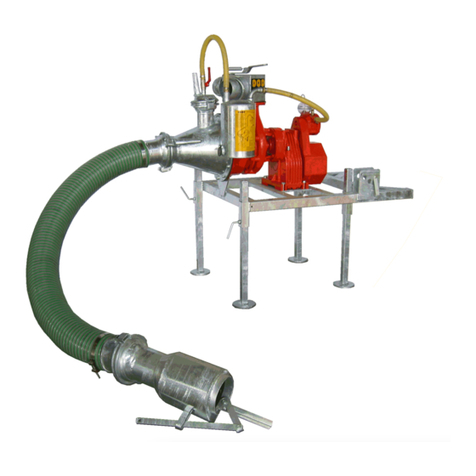
DODA Super ME 80 User manual

®
DODA U.S.A. INC.
255 16TH ST. SOUTH
ST.JAMES, MN 56081
P: 507.375.5577 F: 507.375.5578
USE AND MAINTENANCE MANUAL
VERTICALME PUMPS

All right reserved, copyright of this manual only under li-
cense from DODA i.n.c.
Data and measures written in this manual are approximate
and there may be some changes without warning.

DODA thanks you for buying an item in its production and invites you to read this use
and maintenance manual.
You will find within this manual information necessary for correct use and maintenance
of the machine you have purchased so please carefully follow the directions.
Please also keep this manual in a safe place for future reference.
The content of this manual may be changed without notice in order to make changes or
improvements to units already sold.
No reproduction or translation of any part of the manual is admitted unless authorized.
DESCRIPTION
Introduction
Machine loading and unloading
General remarks
Preliminary checks
Positioning and Transportation
Operation
Work and Safety Rules
Maintenance
Stickers
Performance and Technical Data
Instructions for dismantling and re-assembling the
pump
Parts View’s
PAGE
1
2
3
4
5
6
8
9
10
11
12
13

6) Handle for cone vertical movement
7) Handle for flow opening and closing
8) Driving line
9) Two-point connection
10) Tightening pin
11) Stand off peg
12) Chopping pump body
1. INTRODUCTION
The machines described in the following ”USE AND MAINTENANCE” manual are a
chopping, emulsifying vertical axis pump.
These pumps are used for managing thick and/or non-homogeneous manure.
They are built standard with the following devices:
double chopping system with blades, counter-blades, rotor, counter-rotor;
Adjustable agitation nozzle enabling the mixing of the treated substance
Manufactured in various models with varied performance and power absorption, they are
supplied in the following versions: with pto shaft, powered by electric or hydraulic mo-
tors.
The galvanized structure, the oil-bath driveline system and the high quality of materials
used assure the machines high durability and simple maintenance.
From the technological point of view, the concept adopted for all other DODA products
has been applied to this machine, too:
" Highest quality to obtain the maximum reliability and durability. "
pg. 1
fig. 1
1
2
3
5
8
10
9 11
12
4
7
6
1) Carriage for SUPER 120-150 -
200
2) Gear box
3) (Manual) cone orientation crank
4) Discharge pipe.
5) Adjustable cone for agitation

pg. 2
2. MACHINE LOADING AND UNLOADING
The machine loading and unloading operation can be carried out by:
lift truck;
hoisting crane.
* Make sure the carrying sling or chain used to lift is sufficient to lift the weight of
the pump *
WARNING: in either case the machine must not be lifted by the weakest parts of
the structure (delivery pipes, etc...).
WARNING : before lifting the structure, be sure that it is well-balanced.
fig. 4
fig. 2
fig. 3
SUPER PUMPS :
PTO DRIVEN
ME PUMPS:
ELECTRIC DRIVEN

pg. 3
1) Check that no components of the pump have undergone damages during transporta-
tion. If damages have occurred, contact your DODA dealer immediately.
2) The connection to power supply must be carried out according to DODA instruc-
tions, by specialized staff (by connecting the cables of the electric motor to the in-
put or the pump to the tractor by means of the pto shaft). DODA is in no way re-
sponsible for any electric connection, (please follow instructions on the motor tag
as well as on the sticker showing the rotation direction).
3) Before starting the machine check that the rotary driving parts are adequately pro-
tected, as foreseen by their manufacturer.
4) If the protection of a rotary part is not an issue, it must be carried out by the opera-
tor in conformity with prevailing law.
5) DODA takes no responsibility for modifications altering the characteristics of the
machine bought.
6) Before operating the machine it is necessary to carefully read all directions in the
“Instructions for Use and Maintenance” manual. In particular, be sure that you
have completely understood the machine operation.
7) The machine has been designed and built to treat water and sewage, not for
chemical products. Handling these substances can cause permanent damage to
this machine.
8) Check that the machine length is adequate to the depth of the tank.
9) In regards to machines with oil-bath drive, the driving pipe as well as the geared
units (if present) must be filled with oil prior to use.
10) Carefully avoid that machine rubber parts do not come into contact with oil,
grease or oil derivatives.
3. GENERALWARNING

pg. 4
4. PRELIMINARY CHECKS
Our machines may be supplied with lubricating oil either in the driveline or in the gear-
box units. Before starting the machine, check oil levels and if necessary fill then ma-
chine with oil.
- unscrew caps: fill with oil and blow air out.
- Pour oil very slowly see oil quantity on table;
- fill with high-temperature resistant, synthetic oil (ONLYAFI REVERSE GEAR)
- wait at least 1 hour before checking the oil level (ONLY FOR DRIVING PIPES);
- close caps.
- Check the level cap periodically: oil must never be under that level.
The driving pipe must be vertical during filling and inspection operations.
INDICATIVE OIL QUANTITY LEVELS FOR DRIVING PIPE
Pump length 1m/3’ 1.5/5’ 2m/6’ 2.5m/8’ 3m/10’ 3.5m/11’ 4m/13’
Oil quantity (kg) 0.5 0.5 0.5 3.2 4.7 5.6 6.6
Pump length 4.5m/15’ 5m/16’ 5.5m/18’ 6m/19’ 6.5m/21’
Oil quantity (kg) 10.2 11 12.2 13.5 16.5
1) Oil fill
2) Oil breather
3) Oil level
fig. 6
1
3
2
Driveline 80/90w

pg. 5
As far as the machines powered by electric motor are concerned, DODA is not respon-
sible for any electric connection (please carefully follow directions on plate on motor
as well as on sticker indicating the rotation direction).
For transporting the machine over long distances, load it on a proper vehicle by follow-
ing directions indicated in paragraph “MACHINE LOADING AND UNLOADING”.
Never use a tractor for machine transportation on roads.
5. POSITIONING AND TRANSPORTATION
fig. 8
fig. 9
fig. 10
If the tank bottom is reached, lift the machine a few
inches by means of the winch—if available.
The version with electric motor
and wall connection is connected
fig. 13 by simply resting the wall
bracket with adjustable legs on
the tank wall.
A

pg. 6
Legs are adjustable according to tank side thickness. These
pumps are normally stationary, but a (manual or electric)
winch can be added to them on request for lifting and lowering
the pump.
fig. 13
Model Special 120 (powered by an electric motor) is provided with a three-wheeled
carriage suitable for autonomous shifts. This model is specially indicated for narrow,
ground-level tanks since the pump, once placed on the on top of the opening can be
vertically lowered.
6. WORKING
WARNING: read section “GENERAL INSTRUCTIONS” before starting the ma-
chine.
After arranging the machine and checking its stability during normal functioning you
can start utilising it.
As for all versions provided with an electric motor, after checking the correct rotation
direction, connect to power supply.
fig. 12
fig. 10
fig. 11

pg. 8
Cone rotation is carried out by means of the hand crank fig.
17 on the output pipe.
WARNING: if the manure is very liquid, some sub-
stance may come out of the output pipe during pumping
operation, even if the valve is completely closed.
fig. 17
7. WORK AND SAFETY RULES
1) During machine inspections, while working, always wear proper clothing
(overalls, gloves, helmet, accident prevention shoes, fastened clothes, etc...).
2) The machine must always be utilized where well lit.
3) Since gases released by liquid manure are poisonous, check that:
- the work area is adequately ventilated;
- the machine is not operated in proximity to flames.
4) Never inspect the liquid manure tank alone. You could loose your balance or be-
come faint due to fumes, always ask for help.
5) If you do not need to work in a tank, cover it.
6) The machine must be operated by accountable adults, while the place must not be
accessible to children.
7) Do not carry out operations or regulations when the machine is in motion or when
it is connected to power supply.
8) The machine must only be employed with all protections correctly positioned, fol-
lowing instructions indicated in the previous paragraphs to avoid possible contact
with moving parts. Do not damage or remove those protections.
9) The machine must never be operated without having filled oil-tank (driving pipes
and geared units).

11) During maintenance be sure that the machine is stable and disconnected from power
supply.
12) The carriage must not be used for road-transportation.
13) During operation or maintenance avoid contact of machine rubber parts (gaskets,
etc...) with oil, grease or oil derivatives.
14) Be sure that motor rotation is clockwise as indicated by the arrow on the motor
(when engaged).
15) As for electrically operated machines, connection must be carried out in a place pro-
tected from rainfall.
16) If delivery is connected to pipes or hoses, check that the special fastening joints are
under perfect conditions; do not stop near them: hazard of bursting and tearing.
17) Work and keep the machine in a dry area, protected from rainfall if it is not utilized
for a long time.
pg. 9
Before carrying out any maintenance operation stop the machine and disconnect it
from supply.
1) Check the oil level regularly in machine parts requiring lubrication, (driving pipes
and geared units) and replace oil completely every 2 years.
2) Grease rotary parts every 50 working hours (lubricators, piston articulated joints, gear
wheels, etc...).
3) At the end of its utilization, wash the machine to prevent liquid manure from solidify-
ing: this could cause damages over time.
4) Wear of blade and impeller must be checked periodically. Replace them if necessary.
As for all spare parts, address DODAauthorized dealers directly.
8. MAINTENANCE

pg. 10
9. STICKERS
OPERATIONS TO BE DONE THROUGH THE LEVERS OF
DELIVERY PIPE.
PRIMA DELL’USO RIEMPIRE D’OLIO
WARNING: fill with oil up to the maxi-
mum level before using the machine
80/90W.
OIL LEVEL
THIS STICKER REMINDS YOU TO CHECK
THE ROTATION DIRECTION OF THE MA-
CHINES ELECTRIC MOTOR BEFORE
STARTING THE MACHINE.
The machine is provided with the following stickers:

pg. 11
10. PERFORMANCE AND TECHNICAL DATA
Pump model / hp.
Outlet pipe (ømm)
Imperller
revolution
Capacity
H (m)
HP
HP electric
motor
Super ME 80
80
1450
1300
5
2-2.5
5
Super ME 100
100
1450
2000
7.5
6.5-7
7.5
Super ME 120
Ultra ME 120
120
1450
2800
15
10-12
12.5
Super ME 120
Ultra ME 120
120
1450
3000
18
12-14
15
Super ME 120
Ultra ME 120
120
1450
3400
22
17-19
20
Super ME 120
Ultra ME 120
120
1450
3800
24
22-24
25
Super 120
120
1600
4000
25
40-60
-
Super 150
Ultra 150
150
1600
6500
30
60-100
-
Super 200
200
1600
11000
50
80-130
-
The whole structure is hot-galvanized and assure pump duration: the pump needs mainte-
nance very rarely, thanks to its oil-bath drive. The technical features assuring a DODA
high reliability are multiple:
- Pump bodies made of nodular cast iron and stainless steel or hot-galvanized metal
structural work.
- Pump body shafts made of stainless steel AISI 304
- Impellers made of stainless steel, nodular cast iron, hardened steel.
- Pressed blades made of hardened manganese-vanadium alloy steel.
- Drive-column made of a hot-galvanized. High-resistance mechanic pipe.
- Drive shaft made of a drawn round bar 30 with dovetailing in C40
- Oversized multiplier.
- Mechanical widia carbide oil seal.

11. INSTRUCTIONS FOR DISMANTLING AND
RE-ASSEMBLING THE PUMP
pg. 12
To remove the impeller, tighten two bolts in the
holes “A” shown in the picture, until the
complete ejection of the impeller itself.
The counter-impeller (pressure plate) must be re
-assembled with the wider part closest to body
outlet (as shown in fig.19)
When assembled, the reverse-impeller should
skim the impeller vanes (as close as possible
without touching it of the wider side and as far
away as possible on the opposite side).
fig. 18
fig. 19
To dismantle the pump body follow the numerical progression as shown in the
parts vew. Dismantle fixed blades (1) first and other components afterward.
The rotating chopper blade (2) spins off counter clockwise.
#’s on bearings go towards
chopper blade
Widest part of pressure plate
goes here, nearest the discharge


E1052ME80DRIVELINE
1076OUTERDRIVETUBEFORME801000
1077OUTERDRIVETUBEFORME801500
1143BEARINGHOUSINGME80
1144SHAFT,1.5MME80DRIVELINE‐NEWSTYLE
1145SHAFT,2MME80DRIVELINE‐NEWSTYLE
1146SHAFT,2.5MME80DRIVELINE‐NEWSTYLE
1147SHAFT,3MME80DRIVELINE‐NEWSTYLE
1148SHAFT,3.5MME80DRIVELINE‐NEWSTYLE
1149SHAFT,4MME80DRIVELINE‐NEWSTYLE
BUL5151NUT,M10NY‐LOCK,ZINC
BUL5162BOLT,M10X30,ZINC
BUL5164BOLT,M10X40,ZINC
BUL5982WASHER,M10LOCK,ZINC
BUL6064KEY,8X7X30
BUL6065KEY,8X7X35
BUL7319SNAPRING,EXTERNAL30X2
BUL7568SHIM,1MM
BUL7572SHIM,30X42S.5
BUL7599SHIM,D.30X42S.1
CUS147BEARING,#3206A
CUS167BEARING,#2206‐E2RS1KTN9/C3
CUS168BUSHING,H306
GTP218SEAL,OIL25.40.7
RAC103PIPECAP,1/4",ZINC
E1054ME80DISCHARGETUBE
1121CLAMP,ME80WALLBRACKET
1157TUBE,DISCHARGEME801.5M65"
1158TUBE,DISCHARGEME802M84.5"
1159TUBE,DISCHARGEME802.5M8'104.5"
1160TUBE,DISCHARGEME803M10'124.5"
1161TUBE,DISCHARGEME803.5M12'144"
1162TUBE,DISCHARGEME804M13'164"
BUL5151NUT,M10NY‐LOCK,ZINC
BUL5163BOLT,M10X35,ZINC
FER101ELBOW,90DEGREE80MMDIA.GALVANIZED
GTP108SEAL,DISCHARGEPIVOTTUBEFORME80
GTP109O‐RING,3"80MMRUBBER
Parts descriptions for ME80 driveline & discharge tube. Call your dealer for pricing. Pg.


This manual suits for next models
7
Table of contents
Other DODA Water Pump manuals
Popular Water Pump manuals by other brands

Wilo
Wilo Star-Z 15 TT Installation and operating instructions

EST Group
EST Group Curtiss-Wright POP-A-PLUG PAP-6600-SIL operating instructions

SKF
SKF Spandau Pumpen PSR Series Assembly manual and corresponding operating manual

Nordson
Nordson 25B Customer product manual

Generac Power Systems
Generac Power Systems 0068210 owner's manual

KNF
KNF N 2400.15 Operating and installation instructions