Doepke Dupline DRT 1 User manual

3931226/02/05/B
Doepke
Dupline
Raumthermostat DRT 1
mit Nachtabsenkung
DRT 1 Room Thermostat
with Night-time Reduction
Bedienungsanleitung
Operating Instructions

2 3931226/02/05/B
Doepke
Inhaltsverzeichnis
1. Allgemeines ........................................................................................... 3
2. Kodierung .............................................................................................. 3
3. Inbetriebnahme...................................................................................... 3
4. Anzeigen................................................................................................ 4
5. Garantie................................................................................................. 4
6. Technische Daten.................................................................................. 4
7. Anschlussschema.................................................................................. 5
8. Maße ..................................................................................................... 5
Table of Contents
9. General Information............................................................................... 6
10. Coding ................................................................................................... 6
11. Putting into Service................................................................................ 6
12. Indicators ............................................................................................... 6
13. Guarantee.............................................................................................. 7
14. Technical Data....................................................................................... 7
15. Connection Diagram.............................................................................. 8
16. Dimensions............................................................................................ 8
Sollten Sie Fragen zu diesem Produkt
oder zum Dupline-System haben, wen-
den Sie sich bitte an:
In case of queries concerning this
product or the Dupline system plea-
se contact:
Doepke
Schaltgeräte GmbH & Co. KG
Stellmacherstraße 11
D-26506 Norden, Germany
Tel.: +49 (0) 4931/1806-0
Fax: +49 (0) 4931/1806-101
E-mail:
Internet:
http://www.doepke.de
3931226/02/05/B

3931226/02/05/B 3
Doepke
Bedienungsanleitung
Dupline Raumthermostat DRT 1
1. Allgemeines
Der Raumthermostat DRT 1 ist eine Komponente des Dupline Installationssystems und
erzeugt einen Schaltkanal für die Auswertung über den Dupline-Bus, z.B. zum Schalten
von Heizkörperstellventilen.
Der Thermostat generiert den Schaltkanal in Abhängigkeit der, am Handrad eingestell-
ten, Soll-Temperatur und der Raumtemperatur: liegt die Raumtemperatur unter der ein-
gestellten, aktiviert der DRT 1 den Dupline-Kanal, andernfalls deaktiviert er ihn. Über
einen zusätzlichen Dupline-Kanal kann am DRT 1 zudem eine Nachtabsenkung von 4°C
vorgegeben werden. Die Dupline-Adresse des Schaltkanals ist frei konfigurierbar zwi-
schen A1 und P8, die Nachtabsenkung kann auf einer Adresse innerhalb der B-Gruppe
vorgegeben werden.
Der DRT 1 benötigt keine externe Spannungsversorgung, da er aus den Dupline-Signal-
leitern versorgt wird. Durch seine Bauform passt er in handelsübliche Unterputz-Dosen,
kann jedoch bei Verwendung des mitgelieferten Gehäuses auch aufputz montiert wer-
den.
2. Kodierung
Die Position der Drehschalter ist Kapitel 7 “Anschlussschema” auf Seite 5 dargestellt.
Die Adresse des Schaltkanals wird über die zwei neben einander liegenden Drehschal-
ter (A) zwischen A1 und P8 eingestellt.
Die Adresse des Nachtabsenkungsbefehls ist auf die Gruppe B fest kodiert; die Kanal-
nummer 1..8 lässt sich jedoch am dritten Drehschalter (B) wählen. Wird keine Nachtab-
senkung benötigt, muss der am Drehschalter eingestellte Kanal der B-Gruppe in der
Konfigurationssoftware ProLine unbelegt bleiben.
3. Inbetriebnahme
Die Installation darf nur von einer autorisierten Fachkraft vorgenommen werden. Der
DRT eignet sich zur direkten Aufputzmontage an Wänden oder zum Einbau in einer UP-
Dose. Beim Anschluss ist das Schema auf Seite 5 zu beachten.
Alle anzuschließenden Leitungen müssen spannungsfrei sein. Verbindungen zwischen
dem Dupline-Signal und dem Erdpotenzial führen zu Störungen und sind nicht zulässig.
Auf die richtige Polarität des Dupline-Signals ist zu achten. Folgende Tabelle zeigt die
Anschlussbelegung:
Um den Forderungen für Schutzkleinspannung zu genügen, ist bei der Installation die
VDE0100, Teil 410 zu beachten und anzuwenden.
Klemme Beschreibung Klemme Beschreibung
1 Dupline Signalleiter + (Dupline+) 2 Dupline Signalleiter - (Dupline-)

4 3931226/02/05/B
Doepke
4. Anzeigen
5. Garantie
Für fachgerecht montierte, unveränderte Geräte gewähren wir ab Kauf durch den End-
verbraucher die gesetzliche Gewährleistungsfrist. Die Garantie bezieht sich nicht auf
Transportschäden sowie Schäden, die durch Kurzschluss oder Überlastung entstanden
sind. Bei Fertigungs- und Materialfehlern, die innerhalb der Gewährleistungsfrist erkannt
werden, leistet unser Werk kostenlosen Ersatz.
6. Technische Daten
Anzeige Beschreibung
Rote LED Schaltkanal (Heizbefehl):
Aus: Temperatur überschritten / An: Temperatur unterschritten
Min. Typ. Max.
Dupline
Stromaufnahme 2,5 mA
Eingangskanäle 1 Schaltkanal für z.B. Stellventile
Ausgangskanäle 1 Steuerkanal für Nachtabsenkung
Temperatursteuerung
Messbereich +14°C +28°C
Hysterese -0,25°C +0,25°C
Nachtabsenkung -4°C (auf Adressgruppe B)
Betriebsspannung
Nennbetriebsspannung nicht erforderlich (aus Dupline-Signalleiter)
Anschlüsse
Art Bügelklemme
Klemmbereich 0,4 mm ∅2,5 mm²
Gehäuse
Art Gehäuse für AP- und UP-Montage
Maße 84 x 84 x 34 (B x H x T in mm)
Material ABS, weiß
Allg. technische Daten
Betriebstemperatur -30°C +60°C
Schutzart / Normen IP20
Bestellnummer, -bezeichnung 09 501 171, DRT 1

3931226/02/05/B 5
Doepke
7. Anschlussschema
8. Maße
Dupline +
Dupline -
12
3931226_1A
G
H
I
J
K
L
M
N
O
P
A
B
C
D
E
F
1
.
2
.
3
.
4
.
5
.
6
.
7
.
8
1
.
2
.
3
.
4
.
5
.
6
.
7
.
8
Adresseinstellung Schaltkanal (A)
Adresseinstellung Nachtabsenkung (B)
84,0
84,0
3931226_2A
46,0
55,8
4,6
55,8
18,0
Einbautiefe
19,0
Aufputz-Rahmen
84,0
14
16
18
20 22
24
26
28

6 3931226/02/05/B
Doepke
Operating Instructions
Dupline DRT 1 Room Thermostat
9. General Information
The DRT 1 room thermostat is a component of the Dupline installation system and gen-
erates a switching channel for evaluation via the Dupline bus, e.g. for regulating radiator
control valves.
The thermostat generates the switching channel according to the desired temperature
set at the valve and the actual room temperature. If the room temperature is below the
set value, the DRT 1 will activate the Dupline channel or, conversely, deactivate it. Via an
additional Dupline channel the DRT 1 can also be preprogrammed for a 4ºC lowering at
night-time. The Dupline address is freely selectable between A1 and P8, the night-time
reduction can be preset at an address within the B-group.
The DRT 1 requires no external power source as it is supplied by the Dupline signal. Al-
though its compact design makes it suitable for installation in flush-mounted socket box-
es, it may also be surface-mounted by using the housing supplied.
10. Coding
The position of the rotary switch is illustrated in chapter 15 “Connection Diagram” on
page 5. The address of the switching channel can be set between A1 and P8 via the two
adjacent rotary switches (A).
The address for the night-time reduction command is permanently encoded in the B-
group; the channel number 1...8 may, however, only be selected with the third rotary
switch (B). If no night-time reduction is required, the channel of the B-group set at the ro-
tary switch must remain unassigned in the ProLine configuration software.
11. Putting into Service
Commissioning may only be carried out by an authorised trained technician. The DRT is
suitable for direct surface mounting on walls or for installation in flush-mounted socket
boxes. Follow the connection diagram on Page 8 when installing.
All lines to be connected must be dead. Connections between the Dupline signal and
earth potential will cause malfunctions and are not permissible. Check that the polarity of
the Dupline signal is correct. The following table illustrates the connection configuration:
In order to meet the requirements for protective low voltage, VDE0100, Part 410, should
be observed and put into practice during installation.
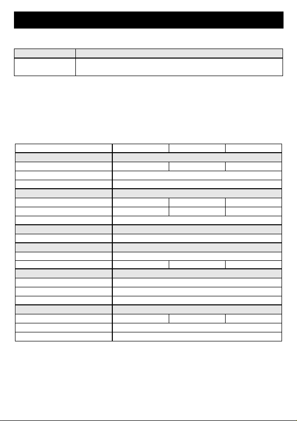
12. Indicators
Pin Description Pin Description
1 Dupline signal conductor+
(Dupline+)
2 Dupline signal conductor-
(Dupline-)
Indicator Description
Red LED Switching channel (heating command):
Off - Temperature exceeded / On - Temperature too low

3931226/02/05/B 7
Doepke
13. Guarantee
All professionally installed, unaltered devices are covered by warranty during the statu-
tory guarantee period from the day of purchase by the end user. The guarantee is not ap-
plicable to damage incurred during transport or caused by short-circuit or overloading. In
the event of defects in workmanship or material, which are discovered within the guar-
antee period, the company will provide a replacement free of charge.
14. Technical Data
Min. Typ. Max.
Dupline
Current input 2.5 mA
Input channels 1 switching channel for e.g. control valves
Output channels 1 control channel for night-time reduction
Temperature sensor
Measuring range +14°C +28°C
Hysteresis -0.25°C +0.25°C
Night-time reduction -4°C (at address group „B“)
Operating Voltage
Rated operating voltage Not required (supplied by Dupline signal line)
Terminals
Type Clevis terminal
Contact area 0.4 mm ∅2.5 mm²
Housing
Type Housing for flush- and surface-mounting
Dimensions 84 x 84 x 34 (W x H x D in mm)
Material ABS, white
General technical data
Ambient temperature -30°C +60°C
Encl. protection type /
standards IP20
Order number, description 09 501 171, DRT 1

8 3931226/02/05/B
Doepke
15. Connection Diagram
16. Dimensions
Dupline +
Dupline -
12
3931226
_
1A
G
H
I
J
K
L
M
N
O
P
A
B
C
D
E
F
1
.
2
.
3
.
4
.
5
.
6
.
7
.
8
1
.
2
.
3
.
4
.
5
.
6
.
7
.
8
Address setting, switching channel (A)
Address setting, night-time reduction (B)
84,0
84,0
3931226_2EA
14
16
18
20 22
24
26
28
46,0
55,8
4,6
55,8
18,0
Installation depth
19,0
84,0
Surface-mounted frame
84.0
18.0
55.8
46.0
55.8
19.0
84.0
84.0
4.6
Table of contents
Languages:
Other Doepke Thermostat manuals