3931226/2009.06/C - The right to make technical changes reserved! 5
Doepke
English
1- Table of Contents
Operating Instructions
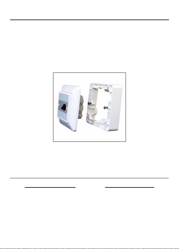
DRT 1 Room Thermostat
8. General Information
The DRT 1 room thermostat is a component of the Dupline installation system and gen-
erates a switching channel for evaluation via the Dupline bus, e.g. for regulating radiator
control valves.
The thermostat generates the switching channel according to the desired temperature
set at the valve and the actual room temperature. If the room temperature is below the
set value, the DRT 1 will activate the Dupline channel or, conversely, deactivate it. Via an
additional Dupline channel the DRT 1 can also be preprogrammed for a 4ºC lowering at
night-time. The Dupline address is freely selectable between A1 and P8, the night-time
reduction can be preset at an address within the B-group.
The DRT 1 requires no external power source as it is supplied by the Dupline signal. Al-
though its compact design makes it suitable for installation in flush-mounted socket box-
es, it may also be surface-mounted by using the housing supplied.
9. Important Notes in Advance
In order to protect both life and components, please observe the following safety in-
structions:
• Installation may only be carried out by authorised, trained technicians.
• The Dupline signal supply has to be delivered by sources, which have to be installed
in accordance with theregulations governing protective low-voltage (see VDE 0100,
Part 410, or EN 50090-9-1) as well as the installation has to comply with these re-
quirements. Even if extensive protective measures have been implemented in the
device, other voltages at the signal inputs could result not only in the destruction of
the device, but also endanger people. For further information please refer to the Du-
pline Planning Aid.
10. Coding
For DRT 1, the coding is carried out by means of rotary switches - the position of the ro-
tary switches is illustrated in Chapter 15 “Anschlussbeisp. / Conn. Example” on page 8.
The address of the switching channel can be set between A1 and P8 via the two adjacent
rotary switches (A).
The address for the night-time reduction command is permanently encoded in the B-
group; the channel number 1...8 may, however, only be selected with the third rotary
switch (B). If no night-time reduction is required, the channel ofthe B-group set at the ro-
tary switch must remain unassigned in the ProLine configuration software.
11. Putting into Service
The DRT is suitable for direct surface mounting on walls or for installation in flush-moun-
ted socket boxes. Follow the connection diagram on page 8 when installing.
All lines to be connected must be dead. Connections between the Dupline signal and