Doheny's 5216 Guide

Small Sand Filter
Item #5216
6950 51st Street Kenosha WI 53144|Orders and Customer Care: 1-800-574-7665|Fax: 1-800-323-5932|Doheny.com
▲WARNING
This equipment must be installed and serviced by a qualied technician in accordance with all applicable codes
and ordinances. Improper installation can create hazards which could result in property damage, serious injury
or death. Improper installation will void the warranty. The NOTICE label indicates special instructions that are
important but not related to hazards.
Notice to Installer
This manual contains important information about the installation, operation and safe use of this product. Once
installation is complete, this manual must be given to the owner / operator of this equipment.
INSTALLATION, OPERATION & PARTS

CHAPTER 1:
IMPORTANT SAFETY INSTRUCTIONS
READ AND FOLLOW ALL INSTRUCTIONS
1. The sand lters are designed to work with water
temperature between 32ºF and 113ºF. The
lter should never be operated outside of these
temperatures or damage may occur.
2. The installation should be carried out in accordance
to the safety instructions of swimming pools and
the specic instructions for each facility.
3. The user should make sure that the installation is
carried out by qualied authorized persons and that
these persons have rst carefully read the following
instructions. Incorrectly installed equipment may
fail, causing sever injury or property damage.
4. The operating safety of the lter is only guaranteed if
the installation and operation instructions are
correctly followed.
5. To reduce the risk of injury, do not permit children
to use this product.
6. Chemical spills and fumes can weaken Swimming
Pool or Spa. Corrosion can cause lters and other
equipment to fail, resulting in severe injury or
property damage. Do not store pool chemicals near
your equipment.
7. Any modication of the lter is not authorized. The
supplier assumes no liability for the damage and
injuries caused by unauthorized replacement parts
and accessories.
Sand Filtration System Working Principle
Incoming water from the piping system is automatically
directed by the Multi-Port Valve to the top of the lter
bed. As the water is pumped through the lter sand,
dirt and debris are trapped by the lter bed, and ltered
out. The ltered water is returned from the bottom of
the lter tank, through the Multi-Port Valve and back
through the piping system.
CHAPTER 2: PREPARATION BEFORE INSTALL
▲WARNING This product should be installed and
servicedonlybyaqualiedprofessional.
1.
Position the lter next to the Swimming Pool or Spa.
2. The lter should be placed on a level concrete
slab, very rm ground, or equivalent. Ensure that
the ground will not subside, preventing any strain
from the attached plumbing.
3. Position the lter so that the piping connections,
Multi-Port Valve and winter drain is convenient and
accessible for operation, servicing and winterizing.
4. Ensure that the compliance label is facing the
front to allow easy identication in the case of
service difculties.
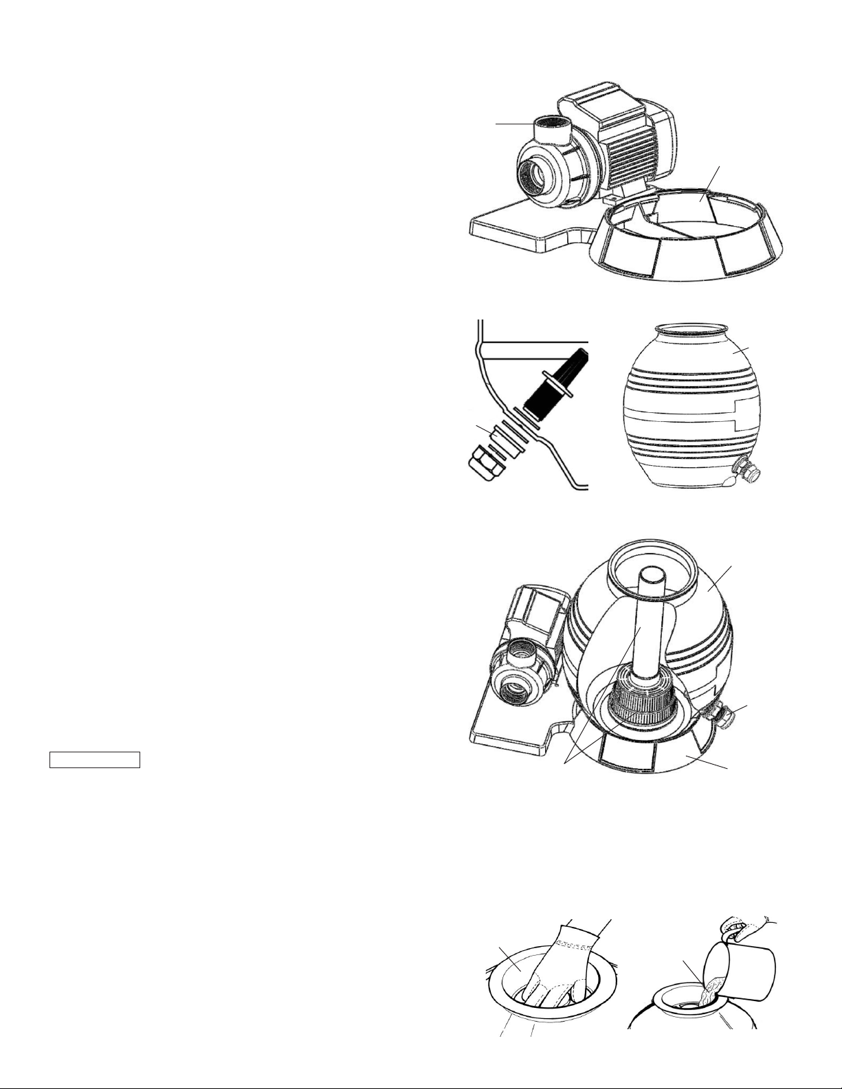
CHAPTER 3: INSTALLATION INSTRUCTIONS
1. Mount the pump to Sand Filter Support by using
the nuts and bolts.
2. Install the Drain Plug Assembly to the Sand Tank.
3. Mount Sand Tank to Sand Filter Support. Drain Plug
is on the outside.
4. Insert the Filter Assembly with Stand Pipe inside
the Sand Tank as pictured above. Then place the
Stand Pipe Blocker over the Sand Tank’s mouth
to prevent sand from getting into the Stand Pipe
and to keep the Stand Pipe in place. Then pour the
Silica Sand (41.8 lbs) into the Sand Tank.
6950 51st Street Kenosha WI 53144|Orders and Customer Care: 1-800-574-7665|Fax: 1-800-323-5932|Doheny.com
Sand Filter
Support
Sand Filter
Support
Pump
Drain
Plug
Drain
Plug
Sand
Tank
Sand
Tank
Filter Assembly
with Stand Pipe
Stand Pipe
Blocker
Silica
Sand

6950 51st Street Kenosha WI 53144|Orders and Customer Care: 1-800-574-7665|Fax: 1-800-323-5932|Doheny.com
5. Remove the Stand Pipe Blocker and clean the
Sand Tank neck carefully.
6. Connect the Multi-Port Valve to the Sand Tank by
using the O-Ring and the Flange Clamp Set. Note:
the direction of PUMP port on valve needs to face
pump out port.
7. Connect the Sand Tank to the Pump with Hose,
Hose Clamps and Hose Adaptors.
Plumbing
1. Make sure the lter is worked under the work
pressure and using a pressure control valve when
the system is using a booster pump.
2. If the pump position is higher than the water level,
it requires to install the back water control valve.
3. If the pump position is lower than the water level,
it requires installing an isolation valve. It could stop
the water return back when people do the general
inspection.
4. Minimize the length of pipe and the number of
ttings to minimize friction loss to ensure maximum
efciency.
5. Connect all plumbing to the Multi-Port Valve taking
care that all joints are glued or tightened securely
to prevent leaking.
6. To prevent breakage and damage to the pump and
Multi-Port Valve, use only pipe sealants specically
formulated for plastics.
7. Ensure solvents are not excessively applied to
ttings as this could run into O-Rings and create
sealing problems.
8. Do not over tighten ttings or adapters.
CHAPTER 3: MULTI-PORT VALVE OPERATION
1. Filter: Position for ltering the body of water.
Incoming water from the piping system is
automatically directed by the Multi-Port Valve to the
top of the lter bed. As the water is pumped through
the lter sand, dirt and debris are trapped by the
lter bed, and ltered out. The ltered water is
returned from the bottom of the lter tank, through
the Multi-Port Valve and back through the piping
system.
2. Backwash: Position for cleaning the lter media.
Water ow is reversed by the Multi-Port Valve
through the lter bed so that water ow is directed
to the bottom of the tank and up through the lter
bed, ushing the previously trapped dirt and debris
out the waste line.
3. Rinse: Position for ushing the lter system.
The water ow is directed by the Multi-Port Valve
through the lter bed and out the waste line. This
process settles the lter media bed into place and
ensures any dirt or debris is rinsed out of the lter,
preventing possible return to the Swimming Pool or Spa.
4. Waste: Position for bypassing the lter bed to
Waste. The water ow is directed by the Multi-Port
Valve straight to the backwash outlet, bypassing the
entire lter bed. This Multi-Port Valve position is used
to lower the water level or for vacuuming water with
high dirt loads.
Backwash
Filter
Waste

6950 51st Street Kenosha WI 53144|Orders and Customer Care: 1-800-574-7665|Fax: 1-800-323-5932|Doheny.com
CHAPTER 4: INITIAL STARTUP OF FILTER
Recheck that all the connections have been made
and are secure, and that the lter media was added
to the tank.
1. Depress Multi-Port Valve handle and rotate to the
BACKWASH position. NOTE: To prevent damage
to control valve seal, always depress handle
before turning.
2. Switch on the Pump. Open the Inlet Valve allowing
the Sand Tank to ll with water. CAUTION: All
suction and discharge valves must be open
when starting the pump. Failure to do so could
cause severe personal injury and/ or property
damage. NOTE: If a pump is installed, switch the
pump on and off, instead of closing and opening
the Inlet Valve.
3. Once water ow is steady out the waste line, run
the pump for at least one minute. The initial
backwashing of the lter is recommended to
remove any impurities or ne sand particles in the
lter media.
4. Turn the pump off. Set the Multi-Port Valve to the
RINSE position. Switch on the Pump. Open the
Inlet Valve until water in sight glass is clear -
approximately 10 to 15 seconds.
5. Switch off the Pump. Close the Inlet Valve, set the
Multi-Port Valve to the FILTER position and Switch
on the Pump. Open the Inlet. Your lter is now
operating in the normal lter mode.
6. Adjust pool suction and return valves to achieve
desired ow. Check the plumbing and lter for water
leaks and tighten connections, bolts, and nuts, as
required. NOTE: During initial clean-up of the
pool water, it may be necessary to backwash
frequently due to the unusually heavy initial dirt
load in the water.
7. Record the pressure gauge reading (start up
pressure) during initial operation. After a period
of time, the accumulated dirt and debris in the lter
causes a resistance to ow, and the ow diminishes.
The pressure will start to rise and the ow of
water will start diminishing. When the pressure
gauge reading is 8-10 PSI higher than the
initial “Start up” pressure, it is time to backwash
(clean) the lter (see Backwashing). NOTE: To
prevent unnecessary strain on piping system
and valving, always shut off the pump before
switching lter control valve position. To
prevent damage to the pump and lter and
for proper operation of they system, clean
pump strainer and skimmer baskets regularly.

REF PART DESCRIPTION No.
No. NUMBER REQ’D
1 647303071001 4-Way Multi-Port Valve 1
2 647303073 Flange Clamp 1
3 65431041080 O-Ring 1
4 647303013931 Filter Tank 1
5 647303074 Filter Assembly with Stand Pipe 1
6 647304073 Drain Plug 1
7 647303012 Sand Filter Support 1
8 647201273 Screw M6X25 and Nut M6 4
9 65431021080 O-Ring 5
10 647303014 Hose Adaptor 5
11 65021004000 Hose Clamp 1
12 65749017011 1-1/4” (32mm) x 45cm Hose 1
13 72714 0.35 HP Pump 1
14 65756006000 Stand Pipe Blocker 1
15 97302 Pressure Gauge 1
16 91215 Plug with O-Ring 1-1/2” MIP 1
6950 51st Street Kenosha WI 53144|Orders and Customer Care: 1-800-574-7665|Fax: 1-800-323-5932|Doheny.com
Above Ground Sand Filter Item # 5216
13
141516
1
2
3
4
5
6
7
8
9
10
11
12
Table of contents
Other Doheny's Water Filtration System manuals