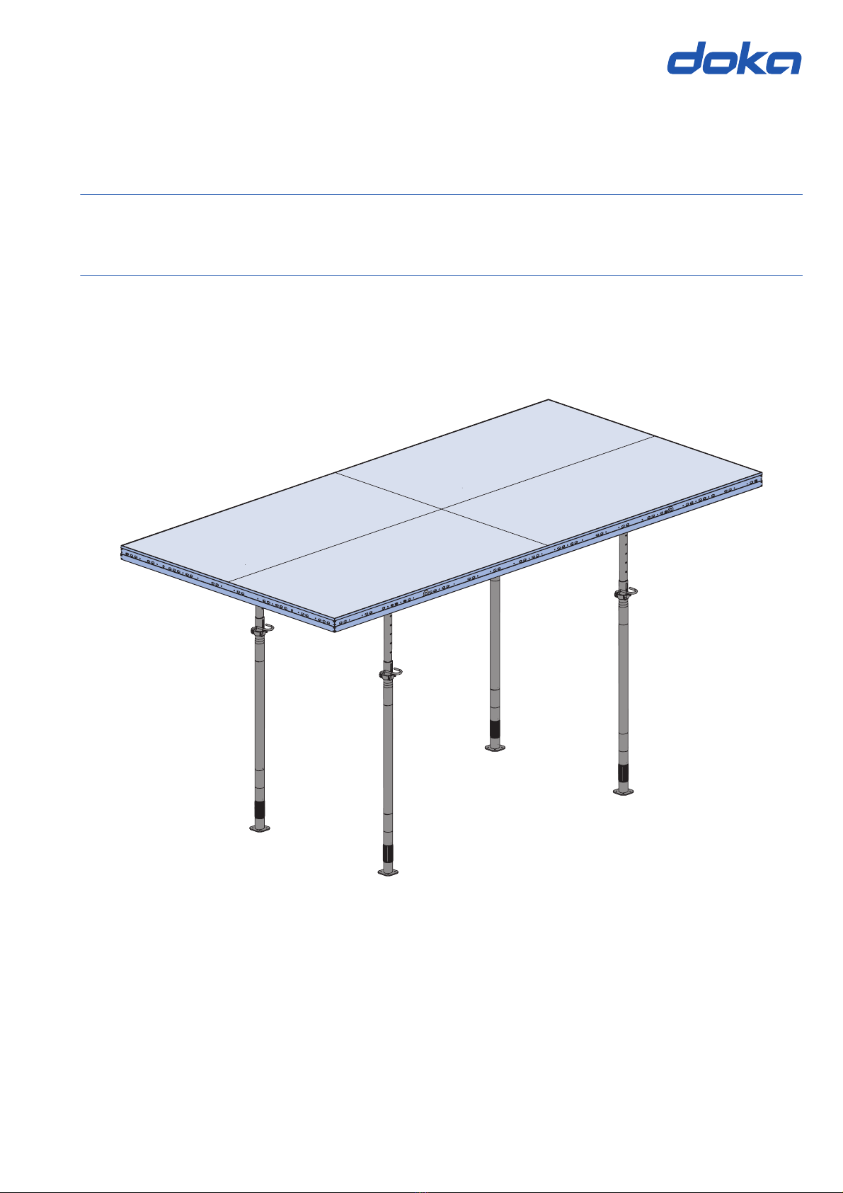
User Information DokaXdek table Introduction
5999820702 - 08/2023
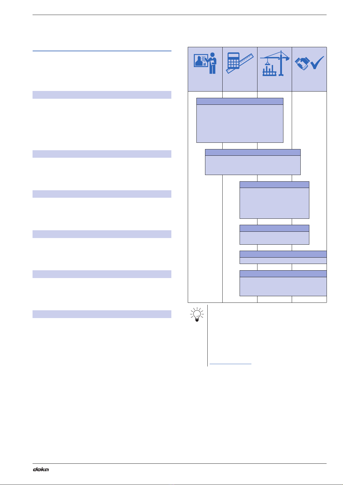
Rules applying during all phases of
the assignment
▪The customer must ensure that this product is
erected and dismantled, reset and generally used for
its intended purpose in accordance with the applica-
ble laws, standards and rules, under the direction
and supervision of suitably skilled persons.
These persons' mental and physical capacity must
not in any way be impaired by alcohol, medicines or
drugs.
▪Doka products are technical working appliances
which are intended for industrial /commercial use
only, always in accordance with the respective Doka
User Information booklets or other technical docu-
mentation authored by Doka.
▪The stability and load-bearing capacity of all compo-
nents and units must be ensured during all phases of
the construction work!
▪Do not step on or apply strain to cantilevers, clo-
sures, etc. until suitable measures to ensure their
stability have been correctly implemented (e.g. by
tie-backs).
▪Strict attention to and compliance with the functional
instructions, safety instructions and load specifica-
tions are required. Non-compliance can cause acci-
dents and severe injury (risk of fatality) and consid-
erable damage to property.
▪Sources of fire in the vicinity of the formwork are pro-
hibited. Heaters are permissible only when used cor-
rectly and situated a correspondingly safe distance
from the formwork.
▪Customer must give due consideration to any and all
effects of the weather on the equipment and regards
both its use and storage (e.g. slippery surfaces, risk
of slipping, effects of the wind, etc.) and implement
appropriate precautionary measures to secure the
equipment and surrounding areas and to protect
workers.
▪All connections must be checked at regular intervals
to ensure that they are secure and in full working
order.
In particular threaded connections and wedged con-
nections have to be checked and retightened as nec-
essary in accordance with activity on the jobsite and
especially after out-of-the-ordinary occurrences (e.g.
after a storm).
▪It is strictly forbidden to weld Doka products – in par-
ticular anchoring/tying components, suspension
components, connector components and castings
etc. – or otherwise subject them to heating.
Welding causes serious change in the microstruc-
ture of the materials from which these components
are made. This leads to a dramatic drop in the failure
load, representing a very great risk to safety.
It is permissible to cut individual tie rods to length
with metal cutting discs (introduction of heat at the
end of the rod only), but it is important to ensure that
flying sparks do not heat and thus damage other tie
rods.
The only articles which are allowed to be welded are
those for which the Doka literature expressly points
out that welding is permitted.
Assembly
▪The equipment/system must be inspected by the
customer before use, to ensure that it is in an accept-
able condition. Steps must be taken to exclude com-
ponents that are damaged, deformed, or weakened
due to wear, corrosion or rot (e.g. fungal decay).
▪Using our safety and formwork systems together
with those of other manufacturers can create risks
that may lead to injury and damage to property. This
requires separate verification by the user.
▪The equipment/system must be assembled and
erected in accordance with the applicable laws,
standards and rules by trained customer personnel
whilst maintaining any applicable safety inspections
that may be required.
▪It is not permitted to modify Doka products; such
modifications constitute a safety risk.
Closing the formwork
▪Doka products and systems must be set up so that
all loads acting upon them are safely transferred!
Pouring
▪Do not exceed the permitted fresh-concrete pres-
sures. Over-high pouring rates overload the form-
work, cause greater deflection and risk breakage.
Stripping the formwork
▪Do not strip out the formwork until the concrete has
reached sufficient strength and the person in charge
has given the order for the formwork to be stripped
out!
▪When stripping out the formwork, never use the
crane to break concrete cohesion. Use suitable tools
such as timber wedges, special pry-bars or system
features such as Framax stripping corners.
▪When stripping out the formwork, do not endanger
the stability of any part of the structure, or of any
scaffolding, platforms or formwork that is still in
place!