Dolby Laboratories DMA 8 User manual

Film-Tech
The information contained in this Adobe Acrobat pdf
file is provided at your own risk and good judgment.
These manuals are designed to facilitate the
exchange of information related to cinema
projection and film handling, with no warranties nor
obligations from the authors, for qualified field
service engineers.
If you are not a qualified technician, please make no
adjustments to anything you may read about in these
Adobe manual downloads.
www.film-tech.com

Model DMA
™
8
Digital Media Adapter
™
Installation Manual
Issue 1 Part Number 91802

Model DMA™8 Installation Manual
ii
Dolby Laboratories, Inc.
Corporate Headquarters
Dolby Laboratories, Inc.
100 Potrero Avenue
San Francisco, CA 94103-4813
Telephone 415-558-0200
Fax 415-863-1373
www.dolby.com/
European Headquarters
Dolby Laboratories, Inc.
Wootton Bassett
Wiltshire, SN4 8QJ, England
Telephone (44) 1793-842100
Fax (44) 1793-842101
Dolby and the double-D symbol are registered trademarks of Dolby Laboratories. Digital Media Adapter, DMA, and Surround EX are
trademarks of Dolby Laboratories. All other trademarks remain the property of their respective owners.
2002 Dolby Laboratories, Inc., all rights reserved.
S02/14328 Issue 1 Part Number 91802

Model DMA™8 Installation Manual
iii
Table of Contents
Chapter 1 Introduction
Regulatory Notices
Chapter 2 Installation
2.1 Unpacking..............................................................................................2-1
2.2 Equipment Required.............................................................................2-1
2.3 Mounting—Proper Grounding..............................................................2-2
2.4 Fuse Information...................................................................................2-2
Check Main Fuse......................................................................................2-2
Internal Fuse .............................................................................................2-3
Mains Power Wiring.................................................................................2-3
2.5 Digital Audio Sources...........................................................................2-4
Professional Interface Standards for Digital Audio..................................2-4
Consumer Interface Standards for Digital Audio.....................................2-5
Multiple Sources—Conversion Between Interface Standards .................2-5
2.6 Connections ..........................................................................................2-6
2.6.1 Digital Media Automation Connector ......................................................2-6
2.6.2 RS-232 Serial Control Port.......................................................................2-7
2.6.3 Serial Data In/Out—Auto Dolby Digital Surround EX Control ..............2-7
2.7 Wiring Diagrams
Wiring to CP500...................................................................................................2-8
Wiring to CP65/DA20..........................................................................................2-9
Wiring to CP55/DA20........................................................................................2-10
Wiring to CP45/DA20........................................................................................2-11
Wiring to CP200/DA20......................................................................................2-12

Model DMA™8 Installation Manual
iv
Chapter 3 Setup
3.1 Setup Software......................................................................................3-1
3.2 Running Setup.......................................................................................3-2
3.2.1 Main Screen..............................................................................................3-2
3.2.2 Change Settings ........................................................................................3-3
3.2.3 Change Settings/Advanced Button...........................................................3-4
Miscellaneous Tab....................................................................................3-4
Channel Assignments Tab........................................................................3-5
Program Selection Tab .............................................................................3-5
3.2.4 Change Settings/View Log.......................................................................3-6
3.2.5 Change Settings/Update Software............................................................3-7
Chapter 4 Operation
4.1 Front-Panel Switches............................................................................4-1
4.2 Power .....................................................................................................4-1
4.3 Surround Delay .....................................................................................4-1
Chapter 5 Technical Reference
5.1 DMA8 Specifications.............................................................................5-1
5.2 DMA8 Repair..........................................................................................5-2
5.3 Serial Port Command Set.....................................................................5-2
5.4 Connectors............................................................................................5-3
5.4.1 Rear-Panel Connector Descriptions and Types........................................5-3
5.4.2 Digital Media Automation Connector ......................................................5-3
5.4.3 Analog Audio In/Out Connector ..............................................................5-4
5.4.4 4x AES In Connector................................................................................5-5
5.4.5 Serial Ports (Front and Rear), RS-232 Connectors ..................................5-6
5.4.6 CP and DA Control Automation Connectors ...........................................5-6
5.4.7 Automation Connections—CP55 with Cat. No. 321................................5-7

Model DMA™8 Installation Manual
v
List of Figures
Figure 2-1 Use Star Washers........................................................................................................2-2
Figure 2-2 Checking the Main Fuse .............................................................................................2-3
Figure 2-3 Rear-Panel View.........................................................................................................2-6
Figure 3-1 Open Device Screen ...................................................................................................3-2
Figure 3-2 Main Screen ................................................................................................................3-2
Figure 3-3 Settings Screen............................................................................................................3-3
Figure 3-4 Change Settings/Advanced—Miscellaneous Tab.......................................................3-4
Figure 3-5 Change Settings/Advanced—Channel Assignments Tab...........................................3-5
Figure 3-6 Change Settings/Advanced—Program Selection Tab ................................................3-5
Figure 3-7 Change Settings/View Log—Event Log ....................................................................3-6
Figure 3-8 Change Settings/View Log—Error Log .....................................................................3-6
Figure 3-9 Change Settings/Update Software ..............................................................................3-7
List of Tables
Table 2–1 Examples of Available Balanced ↔Unbalanced Adapters........................................2-6
Table 5–1 Serial Port Command Strings ......................................................................................5-2
Table 5–2 Rear-Panel Connector Descriptions and Types...........................................................5-3
Table 5–3 Digital Media Connector Pinout..................................................................................5-3
Table 5–4 Analog Audio In/Out Connector Pinout......................................................................5-4
Table 5–5 4x AES In Connector Pinout .......................................................................................5-5
Table 5–6 Serial Ports Pinout .......................................................................................................5-6
Table 5–7 CP and DA Control Connectors Pinout.......................................................................5-6
Table 5–8 CP55 with Cat. No. 321 Installed................................................................................5-7

Model DMA™8 Installation Manual
1-1
Chapter 1
Introduction
Thank you for purchasing the Dolby®Model DMA™8 Digital Media Adapter™. This
new cinema audio tool, a direct result of Dolby’s mission to develop technologies that
improve sound recording and reproduction, allows you to stay at the forefront of
quality entertainment presentation now and into the future.
The DMA8 expands the use of a cinema beyond traditional film applications. It
equips any theatre for a wide variety of uses, providing capabilities far beyond that of
simply showing movies to the general public. The DMA8 enables theatres to provide
audio solutions to today’s alternative programming challenges, such as pay-per-view
events and digital broadcasting.
The unit provides a straightforward interface with existing Dolby cinema processors
CP650, CP500, CP65, CP55, CP45, and CP200. High-quality audio can be presented
from a wide variety of the audio sources:
•High-definition video server
•PCM
•DVD
•Dolby Digital (consumer, non-film-based)
•Broadcast
•Dolby E
The DMA8 is compatible with existing theatre automation. Its accommodation for
multiple formats and future upgrades make it an essential tool for an evolving digital
cinema market.
When the DMA8 is in Film mode, standard six-channel analog signals from any
source, such as a DA20, are routed through the DMA8 to the six-channel input of a
cinema sound processor. In Digital Media mode, the DMA8 decodes and routes
signals from a variety of non-film sources (PCM, DVD, broadcast, Dolby E, and with
an optional Cat. No. 767 card, SDI) to the existing cinema sound processor. The
DMA8 software enables the user to select programs for applications that contain
multiple audio formats.
Like all Dolby cinema sound products, the DMA8 is fully supported by hundreds of
factory-trained technicians worldwide, on-call emergency assistance, and the most
experienced distributor network in the industry.

Model DMA™8 Installation Manual Introduction
1-2
Regulatory Notices
FCC
This equipment has been tested and found to comply with the limits for a Class A digital device,
pursuant to Part 15 of the FCC Rules. These limits are designed to provide reasonable protection
against harmful interference when the equipment is operated in a commercial environment. This
equipment generates, uses, and can radiate radio frequency energy and, if not installed and used in
accordance with this instruction manual, may cause harmful interference to radio communications.
Operation of this equipment in a residential area is likely to cause harmful interference in which case
the user will be required to correct the interference at his or her own expense.
Canada
This Class A digital apparatus complies with Canadian ICES-003.
UL
WARNING: Troubleshooting must be performed by a trained technician. Do not
attempt to service this equipment unless you are qualified to do so.
Check that the correct fuses have been installed. To reduce the risk of fire, replace
only with fuses of the same type and rating.
Exposed portions of the power supply assembly are electrically “hot”. To reduce the risk of
electrical shock, the power cord MUST be disconnected when the power supply assembly is
removed.
The ground terminal of the power plug is connected
directly to the chassis of the unit. For continued protection
against electric shock, a correctly wired and grounded
(earthed) three-pin power outlet must be used. Do not use
a ground-lifting adapter and never cut the ground pin on
the three-prong plug.
UK
The power cord, Dolby Part No. 92021, supplied for use in Europe is not suitable for use in the
UK. To use the cord in the UK, cut off the CEE7/7 plug and replace with an approved
BS 1363 13A plug:
•The core that is coloured green and yellow must be connected to the terminal in
the plug identified by the letter E, or by the earth symbol , or coloured green,
or green and yellow.
•The core that is coloured blue must be connected to the terminal that is marked
with the letter N or coloured black.
•The core that is coloured brown must be connected to the terminal that is marked
with the letter L or coloured red.
•This apparatus must be earthed.

Model DMA™8 Installation Manual Introduction
1-3
EU
This equipment complies with the EMC requirements of EN55103-1 and EN55103-2 when operated in an E2
environment in accordance with this manual.
IMPORTANT SAFETY NOTICE
This unit complies with the safety standard EN60065. The unit shall not be exposed to dripping or splashing and no objects filled with liquids,
such as coffee cups, shall be placed on the equipment. To ensure safe operation and to guard against potential shock hazard or risk of fire, the
following must be observed:
o Ensure that your mains supply is in the correct range for the input power requirement of the unit.
o Ensure fuses fitted are the correct rating and type as marked on the unit.
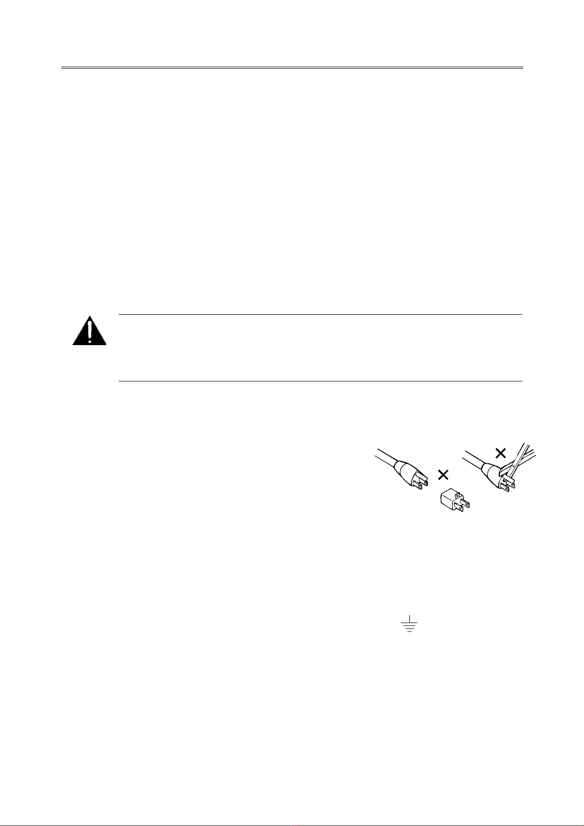
o The unit must be earthed by connecting to a correctly wired and earthed power outlet.
oThepower cord supplied with this unit must be wired as follows:
Live—Brown Neutral—Blue Earth—Green/Yellow
IMPORTANT – NOTE DE SECURITE
Ce materiel est conforme à la norme EN60065. Ne pas exposer cet appareil aux éclaboussures ou aux gouttes de liquide. Ne pas poser d'objets
remplis de liquide, tels que des tasses de café, sur l'appareil. Pour vous assurer d'un fonctionnement sans danger et de prévenir
tout choc électrique ou tout risque d'incendie, veillez à observer les recommandations suivantes.
o Le selecteur de tension doit être placé sur la valeur correspondante à votre alimentation réseau.
o Les fusibles doivent correspondre à la valeur indiquée sur le materiel.
o Le materiel doit être correctement relié à la terre.
o Le cordon secteur livré avec le materiel doit être cablé de la manière suivante:
Phase—Brun Neutre—Bleu Terre—Vert/Jaune
WICHTIGER SICHERHEITSHINWEIS
Dieses Gerät entspricht der Sicherheitsnorm EN60065. Das Gerät darf nicht mit Flüssigkeiten (Spritzwasser usw.) in Berührung kommen; stellen
Sie keine Gefäße, z.B. Kaffeetassen, auf das Gerät. Für das sichere Funktionieren des Gerätes und zur Unfallverhütung (elektrischer Schlag,
Feuer) sind die folgenden Regeln unbedingt einzuhalten:
o Der Spannungswähler muß auf Ihre Netzspannung eingestellt sein.
o Die Sicherungen müssen in Typ und Stromwert mit den Angaben auf dem Gerät übereinstimmen.
o Die Erdung des Gerätes muß über eine geerdete Steckdose gewährleistet sein.
o Das mitgelieferte Netzkabel muß wie folgt verdrahtet werden:
Phase—braun Nulleiter—blau Erde—grün/gelb
NORME DI SICUREZZA – IMPORTANTE
Questa apparecchiatura è stata costruita in accordo alle norme di sicurezza EN60065. Il prodotto non deve essere sottoposto a schizzi, spruzzi e
gocciolamenti, e nessun tipo di oggetto riempito con liquidi, come ad esempio tazze di caffè, deve essere appoggiato sul dispositivo. Per una
perfetta sicurezza ed al fine di evitare eventuali rischi di scossa êlettrica o d'incendio vanno osservate le seguenti misure di sicurezza:
o Assicurarsi che il selettore di cambio tensione sia posizionato sul valore corretto.
o Assicurarsi che la portata ed il tipo di fusibili siano quelli prescritti dalla casa costruttrice.
o L'apparecchiatura deve avere un collegamento di messa a terra ben eseguito; anche la connessione rete deve
avere un collegamento a terra.
o Il cavo di alimentazione a corredo dell'apparecchiatura deve essere collegato come segue:
Filo tensione—Marrone Neutro—Blu Massa—Verde/Giallo
AVISO IMPORTANTE DE SEGURIDAD
Esta unidad cumple con la norma de seguridad EN60065. La unidad no debe ser expuesta a goteos o salpicaduras y no deben colocarse sobre el
equipo recipientes con liquidos, como tazas de cafe. Para asegurarse un funcionamiento seguro y prevenir cualquier posible peligro de descarga o
riesgo de incendio, se han de observar las siguientes precauciones:
o Asegúrese que el selector de tensión esté ajustado a la tensión correcta para su alimentación.
o Asegúrese que los fusibles colocados son del tipo y valor correctos, tal como se marca en la unidad.
o La unidad debe ser puesta a tierra, conectándola a un conector de red correctamente cableado y puesto a tierra.
o El cable de red suministrado con esta unidad, debe ser cableado como sigue:
Vivo—Marrón Neutro—Azul Tierra—Verde/Amarillo
VIKTIGA SÄKERHETSÅTGÄRDER!
Denna enhet uppfyller säkerhetsstandard EN60065. Enheten får ej utsättas för yttre åverkan samt föremål innehållande vätska, såsom
kaffemuggar, får ej placeras på utrustningen." För att garantera säkerheten och gardera mot eventuell elchock eller brandrisk, måste följande
observeras:
o Kontrollera att spänningsväljaren är inställd på korrekt nätspänning.
o Konrollera att säkringarna är av rätt typ och för rätt strömstyrka så som anvisningarna på enheten föreskriver.
o Enheten måste vara jordad genom anslutning till ett korrekt kopplat och jordat el-uttag.
o El-sladden som medföljer denna enhet måste kopplas enligt foljande:
Fas—Brun Neutral—Blå Jord—Grön/Gul
BELANGRIJK VEILIGHEIDS-VOORSCHRIFT:
Deze unit voldoet aan de EN60065 veiligheids-standaards. Dit apparaat mag niet worden blootgesteld aan vocht. Vanwege het risico dat er
druppels in het apparaat vallen, dient u er geen vloeistoffen in bekers op te plaatsen. Voor een veilig gebruik en om het gevaar van electrische
schokken en het risico van brand te vermijden, dienen de volgende regels in acht te worden genomen:
o Controleer of de spanningscaroussel op het juiste Voltage staat.
o Gebruik alleen zekeringen van de aangegeven typen en waarden.
o Aansluiting van de unit alleen aan een geaarde wandcontactdoos.
o De netkabel die met de unit wordt geleverd, moet als volgt worden aangesloten:
Fase—Bruin Nul—Blauw Aarde—Groen/Geel
F
E
NL
S
I
D
GB

Model DMA™8 Installation Manual
2-1
Chapter 2
Installation
2.1 Unpacking
Before unpacking the DMA™8, inspect the outer carton for shipping damage. If the
carton shows damage, inspect the unit in those areas.
Carefully remove the unit from its carton, remove the plastic wrapping, and place on
a flat surface. Look for the following items, which are packed with the DMA8:
•PC setup software
•Power cord
•Spare fuse
2.2 Equipment Required
A PC running Windows®98 or later is required for proper installation of the DMA8:

Model DMA™8 Installation Manual Installation
2-2
2.3 Mounting—Proper Grounding
Various types of noise may be present in and around the projection booth without
audible signs of anything being wrong. Proper mounting and wiring of booth
equipment helps ensure trouble-free performance.
We recommend that star washers be installed on all rack-mounting screws to ensure
good ground contact. This helps prevent electrical noise problems.
Figure 2-1 Use Star Washers
The DMA8 must be mounted in the same rack as the cinema processor to avoid
potential problems with ground loops, radiated interference, and so on.
WARNING: Follow all local codes and regulations covering electrical wiring.
2.4 Fuse Information
WARNING: To reduce the risk of fire, replace fuses only with the same type
and rating.
The DMA8 uses a universal switching power supply that handles the full range of
nominal mains voltages between 100 and 240 VAC, and any frequency between
50 and 60 Hz.
Check Main Fuse
The main fuse rating is:
T 1A L (time-lag, 1 amp, 250 V, 20 mm, low breaking capacity) for all operating
voltages.

Model DMA™8 Installation Manual Installation
2-3
WARNING: Before the following steps are performed, ensure that power to the
unit is disconnected.
1. Use a small flat-blade screwdriver to open the fuse compartment door in the AC
power input housing (Figure 2-2). Carefully pull out the fuse carrier.
2. Check that the fuse has the correct rating. The fuse carrier must be inserted into
the compartment with the orientation shown in Figure 2-2. Do not force the
carrier into the compartment or both could be damaged.
3. Snap the fuse compartment door closed.
Fuse carrier
Installed fuse
Open the door
Figure 2-2 Checking the Main Fuse
Internal Fuse
The switching power supply contains a separate fuse. Most fault conditions should be
protected by the main fuse.
If you find it necessary to replace the internal fuse, be certain to replace it with a fuse
of the same type and rating as printed on the switching power supply board.
Mains Power Wiring
In some countries the primary mains cable may not have a connector fitted. These
non-terminated leads must be properly wired to an approved mains connector in
accordance with the following international code:
Brown wire: Live or hot
Blue wire: Neutral
Green wire: Mains ground
WARNING:If you are uncertain about the wiring of your mains outlet then do
not use it. Consult a qualified electrician.

Model DMA™8 Installation Manual Installation
2-4
2.5 Digital Audio Sources
The DMA8 accepts a wide range of digital audio sources including:
• High-definition video server, player, or receiver
• Professional digital video tape recorder (VTR)
• Digital satellite or cable television receiver
• DVD player
• Terrestrial digital television broadcast
• CD player
A range of digital audio formats are also accepted by the DMA8 including:
• Dolby®Digital (consumer, non-film-based)
• Dolby E
• PCM (digital stereo audio)
All of these sources and formats use one of the following three methods to package
the digital data into a physical connection.
Professional Interface Standards for Digital Audio
There are two professional interface formats used for digital audio: AES/EBU and
AES3. These formats stream the same digital data and professional audio header
information over copper conductor links, but use different types of conductors and
connectors.
AES/EBU uses a balanced connection (two conductors plus shield) with a
characteristic input impedance of 110Ω, nominal peak-to-peak signal level of 5 V,
and most commonly, XLR connectors. AES3 uses an unbalanced connection (one
signal conductor plus shield) with a characteristic input impedance of 75Ω, peak-to-
peak signal level of 1 V, and BNC (“push and twist”) connectors.
Professional digital audio equipment usually uses the AES/EBU format because
balanced operation yields superior noise immunity, as it does with analog audio
signals, and because XLR connectors have been standard on analog professional
audio equipment.
Professional video equipment usually uses the AES3 variation of this interface, with
BNC connectors. Like the use of XLR connectors on pro audio equipment, the
adoption of BNC connectors for the audio on professional video equipment stems
from their existing use for the video signal. Also, the unbalanced AES3 signal can
connect to more than one piece of equipment with the loop-through connectors that
are available on some devices. Lastly, it is robust for long cable runs.

Model DMA™8 Installation Manual Installation
2-5
Consumer Interface Standards for Digital Audio
The consumer interface standard for digital audio is S/PDIF (IEC61937). S/PDIF is
found using either coaxial unbalanced connections (one signal conductor plus shield)
with a characteristic input impedance of 75Ωwith RCA (phono) connectors, or a
fiber-optic cable with Toslink®connectors. The unbalanced coaxial connection has a
peak-to-peak signal level of 0.5 V. Although S/PDIF-specific cables with suitable
connectors can be purchased, good results can also be obtained using high-quality
75Ωvideo cable with the appropriate connectors and/or adapters.
Cable Issues
Even in digital audio, noise-free signals are still very important. The cable used for
digital signals is specifically designed for digital audio use even though it appears to
be the same as that used for analog audio or video signals. Any professional audio
equipment or broadcast supply company can provide 110Ωcable with connectors (or
without, if you wish to terminate them yourself) for AES/EBU connections and high-
quality 75Ωvideo cables with BNC connectors for AES3 connections. Use of cables
or connectors with incorrect impedance or those not designed for digital transmission
compromises the integrity of the bitstream and may create an unreliable link between
pieces of equipment, particularly with long cable runs.
Multiple Sources—Conversion Between Interface Standards
Although some details of the bitstreams used in the AES and S/PDIF standards differ,
the audio information is exactly the same. As a consequence, most audio equipment
accepts either standard with no need to convert the bitstream itself; this is the case
with the DMA8. However, if you intend to connect sources across different types of
digital audio inputs, do not attempt to convert a digital interface type by, for example,
directly wiring an XLR connector to a BNC or RCA plug. This causes an impedance
mismatch and signal reflections, resulting in degradation of the digital waveform. It
may seem to work, but the results are unreliable and dropouts occur.
For conversion between the AES3 and S/PDIF formats you can use high-quality RCA
(phono plug)-to-BNC adapters, since the cable and impedance are the same (75Ω).
For conversion between the AES/EBU and AES3 or AES/EBU and S/PDIF formats,
a simple and economical method is to use inline transformers. These devices perform
the necessary impedance and balanced/unbalanced conversion. The following table
shows some examples of suitable adapters. The unbalanced connector in these
examples is a BNC. BNC-to-RCA adapters can be added to connect to consumer
S/PDIF connections. The units listed use passive circuitry.

Model DMA™8 Installation Manual Installation
2-6
Table 2–1 Examples of Available Balanced ↔Unbalanced Adapters
Adapter Type Neutrik Canare
XLR female 110Ωin
to BNC Female 75Ωout NA-BF BCJ-XJ-TRA
BNC Female 75Ωin
to male XLR 110Ωout NA-BM BCJ-XP-TRA
Higher-priced units incorporating active circuitry are also available. These offer
additional features like multiple inputs, inputs for Toslink digital connections, and
multiple outputs.
2.6 Connections
Refer to the connection diagrams in Section 2.7 for installation wiring to your cinema
processor. The diagrams are located at the end of this chapter. Use the appropriate
page for your cinema processor model. Pinout information on each connector is listed
in Section 5.4
To provide proper operation in locations where there is a large RF or other
interference field, ensure that the cable types, lengths, and pin assignments are strictly
adhered to. Shields must connect only to the chassis and should not be paralleled with
the “–” side of inputs or outputs.
Figure 2-3 Rear-Panel View
2.6.1 Digital Media Automation Connector
The DMA8 provides a ground-switching interface for connecting to a theatre
automation system. The automation system can switch between film sound (pass-
through) and a digital media source. The connector can be wired to automation
systems to switch the DMA8 in and out of Digital Media mode. This function is a
duplication of the front-panel Digital Media and Film buttons.

Model DMA™8 Installation Manual Installation
2-7
2.6.2 RS-232 Serial Control Port
The rear-panel RS-232 connector can be used for serial control of the DMA8 using
ASCII character strings for remote switching and testing. See Section 5.3 for a listing
of the available serial commands. An expanded command set will become available
in future software releases.
2.6.3 Serial Data In/Out—Auto Dolby Digital Surround EX Control
The Serial Data In connector accepts the film sound data bitstream from a
Dolby DA20. The Serial Data To SA10 connector outputs the bitstream to a
Dolby SA10 equipped with an Cat. No. 814A Surround EX™auto-switching board.
Note: SA10s equipped with the original Cat. No. 814 (non-A) board do not need
wiring to this connector. Automatic switching of Surround EX does not
function.
If you have an SA10 equipped with a Cat. No. 814A board, disconnect the existing
serial data cable from the DA20 rear panel and connect it to the DMA8’s Serial Data
To SA10 connector. Add a jumper cable to connect the DA20 Serial Data output to
the DMA8’s Serial Data In connector.
When in Film mode, the film sound data bitstream passes directly from the DA20 to
the SA10, allowing the DA20 to control the Surround EX switching function in the
SA10.
When in Digital Media mode, the DMA8 controls the automatic Surround EX
function of the SA10 by inserting (or not inserting) the Surround EX data flags in the
bitstream to the SA10.
2.7 Wiring Diagrams
This section contains connection diagrams for various cinema processors. Choose the
appropriate diagram based on your installed equipment.

Model DMA™8 Installation Manual Installation
2-8
L+
L–
OPTICAL 2
R–
ANALOG ACC. / MAG.
OPTICAL 1
R+
3
8
7
6
5
4REMOTE
FADER
1
2
NONSYNC 2
X-OVER OUT
HF
LR CRs
BASS
Ls
R
L
RTN
VREF
N/C
DATA
15-24V AC/DC IN
HI Ms
NONSYNC 1
LR
BYPASS PWR / REMOTES
12 5678
LR
MOTOR START
MUX DATA
MUX GND
MUX PWR
RTA
100 - 240 Vac 50-60Hz 120W
5mm x 20mm
FUSE T 2A
Ls Rs SW
6 CHANNEL INPUT
(External Digital Processor)
MIC. INPUT
250V time-lag fuse.
type and rating
replace only with same
To reduce the risk of fire
CAUTION
N/C
PA
PA
(Accessory I/O Only)
DIGITAL ACC.
READER 2
READER 1
SERIAL DATA
AUTOMATION
MODEL CP500
Notes:
1. Follow all local electrical and building codes.
2. Use earthed (grounded) conduit wherever
possible. Avoid routing signal wiring near electric
motors, rectifiers, power wiring, dimmer wiring or
other sources of electrical noise.
3. For two conductor with shield wiring, use
Belden 8451 2-conductor shielded cable or
equivalent: tinned copper, twisted pair, 22 AWG
stranded tinned copper drain wire, aluminum-
polyester shield, 100 percent shield coverage,
conductor to conductor (111pF per meter).
4. All shields must be connected to the CHASSIS
of the CP500 or DMA8 rather than to circuit
(audio) ground. This achieves the RF interference
immunity .
For D-connectors, a metal housing must be used
and the shields must be connected to the housing.
required by European EMC standards
5. Shielded audio cable (Dolby Part No. 83442) is
included in the CDMA/500 cable set shipped to all
countries.
DMA8 TO CP500
INSTALLATION WIRING
FB797A02.CDR
4xAES-3 source
8 channel PCM
from server
5
6
1
1
5
From
Automation
Dolby Part Number
83442
See Note 5.
Digital Media
Push Button
or
Relay Contacts
9
ANALOG AUDIO IN TO DA CONTROL 4xAES IN (8-DIGITAL CH.) S/PDIF
COAX
1xAES
S/PDIF
OPTICAL
AUDIO OUT TOCP TO CP CONTROL
DIGITAL MEDIA AUTOMATION
CONTROL (RS-232)
TO SA10
SERIAL DATA IN
SERIAL REMOTE
SERIAL DATA
SDI
LOOP
OUT IN
CAUTION
To reduce the
risk of fire
replace only with
same type and
rating 250V
time-lag fuse.
FUSE T 1A L
5 mm x 20 mm
100 - 240 Vac 50-60Hz 25W
~
10BASE-T
ETHERNET
DMA8
Risk of electric shock. Do not open. No user serviceable parts inside.
Refer all service to qualified personnel. This equipment must be earthed/grounded.
WARNING: Dolby and the double-D symbol are registered trademarks of Dolby Laboratories.
Digital Media Adapter and DMA are trademarks of Dolby Laboratories.
{
AES-3 Source:
Dolby Digital ( AC3) server
Dolby E server
DVD player
Wiring to CP500

Model DMA™8 Installation Manual Installation
2-9
ANALOG AUDIO IN TO DA CONTROL 4xAES IN (8-DIGITAL CH.) S/PDIF
COAX
1xAES
S/PDIF
OPTICAL
AUDIO OUT TOCP TO CP CONTROL
DIGITAL MEDIA AUTOMATION
CONTROL (RS-232)
TO SA10
SERIAL DATA IN
SERIAL REMOTE
SERIAL DATA
SDI
LOOP
OUT IN
CAUTION
To reduce the
risk of fire
replace only with
same type and
rating 250V
time-lag fuse.
FUSE T1AL
5mmx20mm
100 - 240 Vac 50-60Hz 25W
~
10BASE-T
ETHERNET
DMA8
Risk of electric shock. Do not open. No user serviceable parts inside.
Refer all service to qualified personnel. This equipment must be earthed/grounded.
WARNING:
Dolby and the double-D symbol are registered trademarks of Dolby Laboratories.
Digital Media Adapter and DMA are trademarks of Dolby Laboratories.
Dolby and the double-D symbol are trademarks of Dolby Laboratories Licensing Corporation.
J8
J7
J6
J3
U.S. and worldwide patents pending.
Serial
Data
CP Sense/
Control
Audio In
from CP
Audio Out
to CP
expose this equipment to
or electric shock do not
To reduce the risk of fire
to qualified personnel.
inside. Refer all service
No user serviceable parts
Motor
Start
J9
SOUND PROCESSOR
DIGITAL FILM
MODEL DA20
rain or moisture.
WARNING
H/I
TB3
non-sync in
mag format
NR
NO NR
J24 TB1 R
L
automation inputs
S1S0 S2 S4
S3 S5
E
S7S6 O
/
C
M
U
T
MODEL CP65
auto c/o remote fader
CO
/CEB Rt
pre-amp
AD Lt
TB2
L
Proj 2
R
Proj
2
TB7
HEADER
Format 42
S
R
#2
MAG
From Digital Proj 1
LR
From mpu
Le Re LLs
CRRs
To Power Amps
Ls W
S
Rs LCW
S
TB4
LRC
Notes:
1. Follow all local electrical and building codes.
2. Use earthed (grounded) conduit wherever
possible. Avoid routing signal wiring near electric
motors, rectifiers, power wiring, dimmer wiring or
other sources of electrical noise.
3. For two conductor with shield wiring, use
Belden 8451 2-conductor shielded cable or
equivalent: tinned copper, twisted pair, 22 AWG
stranded tinned copper drain wire, aluminum-
polyester shield, 100 percent shield coverage,
conductor to conductor (111pF per meter).
4. All shields must be connected to the CHASSIS
of the DA20 or DMA8 rather than to circuit (audio)
ground. This achieves the RF interference
immunity .
For D-connectors, a metal housing must be used
and the shields must be connected to the housing.
required by European EMC standards
5. Re-attach existing cables (Dolby part No’s
83134 and 83135) to the DMA8 as shown.
(Cables are included in CDA/65 cable set).
6. Shielded cables (Dolby Part No. 83442) are
included in the CDMA/A cable set.
DMA8 TO CP65 / DA20
INSTALLATION WIRING
FB797B01.CDR
4xAES-3 source
8 channel PCM
from server
5
6
1
1
5
Digital Media
Push Button
or
Relay Contacts
9
Dolby Part Number
83442 2-Places
See Note 6.
Dolby Part Number
83135 (Part of CDA/65)
See Note 5.
Dolby Part Number
83134 (Part of CDA/65)
See Note 5.
{
AES-3 Source:
Dolby Digital ( AC3) server
Dolby E server
DVD player
Wiring to CP65/DA20

Model DMA™8 Installation Manual Installation
2-10
ANALOG AUDIO IN TO DA CONTROL 4xAES IN (8-DIGITAL CH.) S/PDIF
COAX
1xAES
S/PDIF
OPTICAL
AUDIO OUT TOCP TO CP CONTROL
DIGITAL MEDIA AUTOMATION
CONTROL (RS-232)
TO SA10
SERIAL DATA IN
SERIAL REMOTE
SERIAL DATA
SDI
LOOP
OUT IN
CAUTION
To reduce the
risk of fire
replace only with
same type and
rating 250V
time-lag fuse.
FUSE T1AL
5mmx20mm
100 - 240 Vac 50-60Hz 25W
~
10BASE-T
ETHERNET
DMA8
Risk of electric shock. Do not open. No user serviceable parts inside.
Refer all service to qualified personnel. This equipment must be earthed/grounded.
WARNING:
Dolby and the double-D symbol are registered trademarks of Dolby Laboratories.
Digital Media Adapter and DMA are trademarks of Dolby Laboratories.
Dolby and the double-D symbol are trademarks of Dolby Laboratories Licensing Corporation.
J8
J7
J6
J3
U.S. and worldwide patents pending.
Serial
Data
CP Sense/
Control
Audio In
from CP
Audio Out
to CP
expose this equipment to
or electric shock do not
To reduce the risk of fire
to qualified personnel.
inside. Refer all service
No user serviceable parts
Motor
Start
J9
SOUND PROCESSOR
DIGITAL FILM
MODEL DA20
rain or moisture.
WARNING
C
85
CAT.NO.
64B
CAT.NO. CAT.NO.
150 222
CAT.NO. CAT.NO.
240 spare
DABEC
O
/FI BC Lt
TB2
bypass
auto fader
auto c/o
Rt
preamp
MODEL CP55
R
LLR
Proj 2
J15 J16
TB4
J13
test
J18
J9 J11
J10 J12
Proj 1
J14
B/E
LCRS
to power amps
bypass
indicator
TB3
12
TB2
A
J7
1
J8
1A
D
R
CAT.NO.
CAT.NO.
241
CAT.NO.
16 T 64B 64B
CAT
FF
242
28
S7
S6
S5
S4
S3
S2
S1
SO
S8
gnd
S9
mute
TB1
RL
SRCL
RC S
from mag aux non sync
gnd
TB1
ID7
ID6
ID5
ID3
ID4
ID2
indicator
ID0
ID1
remote fader
Voltage select
Notes:
1. Follow all local electrical and building codes.
2. Use earthed (grounded) conduit wherever
possible. Avoid routing signal wiring near electric
motors, rectifiers, power wiring, dimmer wiring or
other sources of electrical noise.
3. For two conductor with shield wiring, use
Belden 8451 2-conductor shielded cable or
equivalent: tinned copper, twisted pair, 22 AWG
stranded tinned copper drain wire, aluminum-
polyester shield, 100 percent shield coverage,
conductor to conductor (111pF per meter).
4. All shields must be connected to the CHASSIS
of the DA20 or DMA8 rather than to circuit (audio)
ground. This achieves the RF interference
immunity .
For D-connectors, a metal housing must be used
and the shields must be connected to the housing.
required by European EMC standards
5. Re-attach existing cables (Dolby part No’s
83132 and 83133) to the DMA8 as shown.
(Cables are included in CDA/55 cable set).
6. Shielded cables (Dolby Part No. 83442) are
included in the CDMA/A cable set.
DMA8 TO CP55 / DA20
INSTALLATION WIRING
FB797D01.CDR
4xAES-3 source
8 channel PCM
from server
5
6
1
1
5
Digital Media
Push Button
or
Relay Contacts
9
Dolby Part Number
83442 2-Places
See Note 6.
Dolby Part Number
83132 (Part of CDA/55)
See Note 5.
Dolby Part Number
83133 (Part of CDA/55)
See Note 5.
To DMA8
AUDIO OUT TO CP
{
AES-3 Source:
Dolby Digital ( AC3) server
Dolby E server
DVD player
Wiring to CP55/DA20

Model DMA™8 Installation Manual Installation
2-11
ANALOG AUDIO IN TO DA CONTROL 4xAES IN (8-DIGITAL CH.) S/PDIF
COAX
1xAES
S/PDIF
OPTICAL
AUDIO OUT TOCP TO CP CONTROL
DIGITAL MEDIA AUTOMATION
CONTROL (RS-232)
TO SA10
SERIAL DATA IN
SERIAL REMOTE
SERIAL DATA
SDI
LOOP
OUT IN
CAUTION
To reduce the
risk of fire
replace only with
same type and
rating 250V
time-lag fuse.
FUSE T1AL
5mmx20mm
100 - 240 Vac 50-60Hz 25W
~
10BASE-T
ETHERNET
DMA8
Risk of electric shock. Do not open. No user serviceable parts inside.
Refer all service to qualified personnel. This equipment must be earthed/grounded.
WARNING:
Dolby and the double-D symbol are registered trademarks of Dolby Laboratories.
Digital Media Adapter and DMA are trademarks of Dolby Laboratories.
*
PROJECTOR 1
J7
R–
PROJECTOR 2
J8
R+
8
COM
P2
P1
1234567
L
R
SW
COM
S
S
COM
L
R
C
13
25
47
68
NON-SYNC 2
AUXILIARYMIC CHANGEOVER
PROJECTOR
INPUTS
IMPAIRED
13
25
47
68
78
13
25
46
J5
J4
LR
OUTPUTS
HEARING
NON
SYNC 1
SW
Rs
HFLF Ls
SW
MODEL CP45
RSLS
HFLF
NORMAL
BYPASS
21 4
3
J1 J2
BOOTH MONITOR OUTPUT
J9
J3
LF
1
HF
3
24
5
HF
678
FULL
RANGE
LEFT
RANGE
FULL
CENTER
LF
LF LF
HF HF
L+
L–
RANGE
CONTROL
LOGIC TO
DIGITAL
PROCESSOR
J12
J10
TO CPU P10
J11
TO AUTOMATION
J6
Dolby and the double-D symbol are trademarks of Dolby Laboratories Licensing Corporation.
J8
J7
J6
J3
U.S. and worldwide patents pending.
Serial
Data
CP Sense/
Control
Audio In
from CP
Audio Out
to CP
expose this equipment to
or electric shock do not
To reduce the risk of fire
to qualified personnel.
inside. Refer all service
No user serviceable parts
Motor
Start
J9
SOUND PROCESSOR
DIGITAL FILM
MODEL DA20
rain or moisture.
WARNING
7
6
54312 8
Notes:
1. Follow all local electrical and building codes.
2. Use earthed (grounded) conduit wherever
possible. Avoid routing signal wiring near electric
motors, rectifiers, power wiring, dimmer wiring or
other sources of electrical noise.
3. For two conductor with shield wiring, use
Belden 8451 2-conductor shielded cable or
equivalent: tinned copper, twisted pair, 22 AWG
stranded tinned copper drain wire, aluminum-
polyester shield, 100 percent shield coverage,
conductor to conductor (111pF per meter).
4. All shields must be connected to the CHASSIS
of the DA20 or DMA8 rather than to circuit (audio)
ground. This achieves the RF interference
immunity .
For D-connectors, a metal housing must be used
and the shields must be connected to the housing.
required by European EMC standards
5. Re-attach existing cables (Dolby part No’s
83306 and 83135) to the DMA8 as shown.
(Cables and Cat.No.545A are included in CDA/45
upgrade kit. All existing Cat.No.545 assemblies
must be upgraded to Cat.No.545A.)
6. Shielded cables (Dolby Part No. 83442) are
included in the CDMA/A cable set.
DMA8 TO CP45 / DA20
INSTALLATION WIRING
FB797C01.CDR
4xAES-3 source
8 channel PCM
from server
5
6
1
1
5
Digital Media
Push Button
or
Relay Contacts
9
Dolby Part Number
83442 2-Places
See Note 6.
Dolby Part Number
83135 (Part of CDA/45)
See Note 5.
Dolby Part Number
83306 (Part of CDA/45)
See Note 5.
Cat.No.545A
(Part of CDA/45)
See Note 5
{
AES-3 Source:
Dolby Digital ( AC3) server
Dolby E server
DVD player
Wiring to CP45/DA20
Other manuals for DMA 8
1
Table of contents
Other Dolby Laboratories Adapter manuals