Dolby Laboratories All-in-Wonder 128 User manual

Dolby Speaker System 128
Owner's Manual
27 October 2021
8800293 Issue 2

Notices
Copyright
© 2021 Dolby Laboratories. All rights reserved.
Dolby Laboratories, Inc.
1275 Market Street
San Francisco, CA 94103-1410 USA
Telephone 415-558-0200
Fax 415-645-4000
http://www.dolby.com
Trademarks
Dolby and the double-D symbol are registered trademarks of Dolby Laboratories, Inc.
The following are trademarks of Dolby Laboratories:
Dialogue Intelligence™
Dolby®
Dolby Advanced Audio™
Dolby Atmos®
Dolby Audio™
Dolby Cinema®
Dolby Digital Plus™
Dolby Digital Plus Advanced Audio™
Dolby Digital Plus Home Theater™
Dolby Home Theater®
Dolby Theatre®
Dolby Vision®
Dolby Vision IQ™
Dolby Voice®
Feel Every Dimension™
Feel Every Dimension in Dolby™
Feel Every Dimension in Dolby Atmos™
MLP Lossless™
Pro Logic®
Surround EX™
All other trademarks remain the property of their respective owners.
Patents
THIS PRODUCT MAY BE PROTECTED BY PATENTS AND PENDING PATENT APPLICATIONS IN THE UNITED
STATES AND ELSEWHERE. FOR MORE INFORMATION, INCLUDING A SPECIFIC LIST OF PATENTS PROTECTING
THIS PRODUCT, PLEASE VISIT http://www.dolby.com/patents.
Product model
This documentation applies to: CS128MH (Model: CID1030), CS128LF (Model: CID1027).
Limited warranty and warranty exclusions
THE LIMITED WARRANTY AND WARRANTY EXCLUSIONS MAY BE FOUND AT THE FOLLOWING URL: http://
www.dolby.com/us/en/about/warranty-and-maintenance-policies.html
Notices
Dolby Speaker System 128 Owner's Manual 2
8800293 Issue 2 27 October 2021

Contents
1 Important safety and regulatory information............................................................................................4
2 Introduction to Dolby Speaker System 128................................................................................................6
2.1 About this documentation....................................................................................................................7
2.2 CS128MH key features and benefits..................................................................................................... 7
2.3 CS128LF key features and benefits.......................................................................................................8
2.4 Dolby Speaker System 128 wire selection............................................................................................9
2.5 Dolby Speaker System 128 installation information........................................................................... 9
2.6 Additional information..........................................................................................................................13
2.7 Contacting Dolby .................................................................................................................................. 13
3 Assembling the Dolby Speaker System 128............................................................................................... 14
3.1 Securing the CS128LF............................................................................................................................15
3.2 Installing the CS128MH onto the CS128LF........................................................................................... 17
3.3 Aiming the Dolby Speaker System 128.................................................................................................18
3.4 Working with electrical components....................................................................................................22
3.5 Connecting and configuring the CS128MH...........................................................................................22
3.6 Connecting and configuring the CS128LF............................................................................................ 24
4 Dolby Speaker System 128 and system components specifications........................................................ 29
4.1 Dolby Speaker System 128 specifications............................................................................................30
4.2 CS128MH specifications........................................................................................................................ 31
4.3 CS128LF specifications..........................................................................................................................32
4.4 Dolby Speaker System 128 and system components dimensions......................................................32
5 Dolby Speaker System 128 digital signal processing requirements......................................................... 34
5.1 CS128MH digital signal processing requirements................................................................................35
5.2 CS128LF signal processing requirements.............................................................................................35
6 System limiters............................................................................................................................................ 37
6.1 Setting system limiters..........................................................................................................................38
7 Documentation revision history................................................................................................................. 39
Contents
Dolby Speaker System 128 Owner's Manual 3
8800293 Issue 2 27 October 2021

1
Important safety and regulatory information
Safety
INSTALLER ASSUMES ALL RESPONSIBILITY AND LIABILITY FOR THE INSTALLATION OF THIS PRODUCT.
No information contained in this guide is intended as a warranty on the part of Dolby. Anyone using
this information assumes all liability arising from its use. Product abuse, use of the product not in
accordance with Dolby instructions, or use in an application for which the product has not been
designed is not covered under any Dolby warranty, nor is Dolby liable for any loss or damage.
Installation must be performed by qualified, licensed, and insured installers, and in accordance with all
laws, rules, and regulations applicable to the installation site. Failure to do so could result in serious
personal injury or even death. Prior to installing this product, read and completely understand the
installation instructions. You must read these instructions to prevent personal injury and property
damage. Keep the installation instructions in an easily accessible location for future reference.
A licensed professional engineer must approve the placement and method of attachment to the
building structure prior to the installation of the system.
All information presented herein is based upon materials and practices common to North America and
may not directly apply to other countries because of diering material dimensions, specifications,
and/or local regulations. Installers in other countries should consult with appropriate engineering and
regulatory authorities for specific guidelines.
Any supplied rigging hardware is intended only for use with the specified loudspeaker(s). The installer
assumes all risk of loss and/or injury arising out of the use of the supplied rigging hardware with any
other loudspeaker. All other rigging is considered part of the venue and/or installer-supplied
equipment and is not addressed in this guide. This guide is not a comprehensive source for rigging in
general. Installer assumes all responsibility for ensuring that accepted rigging and safety practices are
employed. Installer assumes all responsibility for the appropriate use of Dolby supplied rigging
hardware and follows at a minimum all applicable laws, rules, and regulations in force for each venue.
No open flame sources should be placed on or near the apparatus. Do not install near any heat sources
such as radiators, heat registers, stoves, or other apparatus that produce heat.
Storage temperature: -4 to +140°F (-20 to +60°C). The products covered by this manual are not intended
for use in high-moisture environments. Moisture can damage the product and cause corrosion of
electrical contacts and metal parts. Avoid exposing the speakers to direct moisture. Keep speakers out
of extended or intense direct sunlight. Premature product failure or serious personal injury could occur
if this product is used outdoors or in wet indoor environments.
Dolby is not responsible for the application of its products for any purpose or the misuse of this
information for any purpose. Furthermore, Dolby is not responsible for the abuse of its products
caused by avoiding compliance with inspection and maintenance procedures or any other abuse.
Important safety and regulatory information
Dolby Speaker System 128 Owner's Manual 4
8800293 Issue 2 27 October 2021

Caution: Hearing damage can occur by prolonged exposure to excessive sound pressure
level (SPL); the loudspeaker is easily capable of generating SPL suicient to cause
permanent hearing damage to performers, production crew, or audience members.
Caution should be taken to avoid prolonged exposure to SPL in excess of 90 dB.
Caution: Vibration from this type of speaker system is high and may cause cabinets to
shi. Failure to secure the bottom speaker cabinet to the building structure may result in
the speaker system tipping or falling, which may cause damage or injury.
Caution: Make sure that no water pipes, natural gas lines, electrical wire, or conduit are
present where the speaker is to be installed. Cutting or drilling into water pipes, natural
gas lines, electrical wire, or conduit could cause serious personal injury or property
damage.
Caution: Use proper liing techniques when working with heavy objects to avoid
personal injury. Always be careful when moving the CS128LF or the assembled Dolby
Speaker System 128 and employ at least two people when attempting any relocation
of the loudspeakers, as there is danger of tipping if the system is not secured to the
building structure.
High temperature warning: Loudspeaker system may reach elevated temperatures
during operation. Always remove all drive signals and allow ample time for the system to
cool down prior to handling.
EU Environmental regulations/ compliance and product disposal information
Restriction of Hazardous Substances Directive (RoHS): All Dolby products comply with the
requirements of the EU RoHS Directive. This product is electronic equipment and should be disposed
of in accordance with all applicable laws.
Do not dispose as household waste. Do not dispose of the product in a fire. Please dispose of this
product by taking it to your local electronic waste collection point or recycling center. For information
regarding where to recycle electronic equipment, contact your local dealer. For additional information
regarding Waste Electrical and Electronic Equipment (WEEE) and product disposal go to https://
www.dolby.com/us/en/about/environmental-commitment.html
Russian environmental regulations and compliance
This product complies with Russia EAC RoHS requirements.
Dolby Speaker System 128 Owner's Manual 5
8800293 Issue 2 27 October 2021

2
Introduction to Dolby Speaker System 128
The Dolby Speaker System 128 is designed to meet the needs of a high-performance screen speaker in
a large Dolby Atmos or 7.1 Cinema, especially those rooms with minimal space behind the screen. The
Dolby Speaker System 128 delivers consistent audio coverage and uniform volume shading for every
seat in the venue up to approximately 66 feet (20 meters) in depth. The Dolby Speaker System 128
consists of a CS128MH loudspeaker for mid and high frequencies and a CS128LF loudspeaker for low-
frequencies, providing greater intelligibility and enhanced low-frequency extension. These
components are coupled together to create a screen speaker system that provides better audience
coverage, lower distortion (discomfort), and increased low-frequency response. With intuitive
ergonomic design and features, the Dolby Speaker System 128 enables quick, easy installation and
service. Built on the foundation of Dolby’s industry-leading system design and support philosophy, the
Dolby Speaker System 128 provides elevated large-format auditorium performance and streamlines
speaker integration.
Figure 1: Dolby Speaker System 128 full speaker stack
The list below is an outline of this chapter:
•About this documentation
•CS128MH key features and benefits
•CS128LF key features and benefits
•Dolby Speaker System 128 wire selection
•Dolby Speaker System 128 installation information
•Additional information
•Contacting Dolby
Introduction to Dolby Speaker System 128
Dolby Speaker System 128 Owner's Manual 6
8800293 Issue 2 27 October 2021

2.1 About this documentation
This documentation provides key features & benefits of the Dolby Speaker System 128 and how to install the
system in a typical cinematic exhibition environment.
2.2 CS128MH key features and benefits
The Dolby Speaker System 128 utilizes one CS128MH unit, which consists of an asymmetrical high-frequency
horn with a high-performance transducer, and a low distortion 12 inch midrange. This configuration yields
improved pattern and amplitude control within the high-frequency operating range, yielding smoother
response coverage to all seats in the auditorium.
Figure 2: CS128MH rear (le) and front (right)
• The high-frequency driver is a very low-distortion 75 mm titanium dome driver with a frequency response
up to 20 kHz.
• The mid-frequency driver is a high sensitivity 12-inch transducer with optimized FEM (Finite Element
Modeling) motor and suspension, optimized cooling for low power compression and an aluminum
demodulation ring for decreased distortion.
• The cabinet depth is optimized for use in auditoriums with minimal spacing behind the screen.
• The advanced input plate features a high-current, spring-loaded terminal block that enables quick
installation without the need for spade lugs or a crimping tool.
• The CS128MH assembly mounts directly to the top of a CS128LF unit and features independent horizontal
and vertical aiming adjustments.
• The ports on front and back of unit are used for natural convection cooling.
• The unique asymmetrical high-frequency horn design provides long-distance coverage to the back of the
auditorium from the top of the horn, while the bottom of the horn provides wider coverage and volume
shading for the audience closer to the screen. This provides greatly improved coverage for the auditorium
in comparison to conventional horn designs.
About this documentation
Dolby Speaker System 128 Owner's Manual 7
8800293 Issue 2 27 October 2021

Figure 3: Dolby asymmetrical horn coverage
2.3 CS128LF key features and benefits
Dolby Speaker System 128 utilizes a single CS128LF to produce low frequencies.
Figure 4: CS128LF rear (le) and front (right)
• Each unit contains two 15-inch woofers that can be driven in parallel or driven individually to maximize
available amplifier power.
• Each 15-inch driver is contained in an independent chamber within the cabinet that provides improved
performance and reliability.
• On the CS128LF, a unique flip-card allows you to change the electrical routing for parallel wiring of the
drivers powered from a single amplifier channel, or individual wiring to the amplifier channel on each
driver. With the CS128LF flip-card, you can easily select either bi-amplifier mode or single-amplifier mode
without the need of any additional tools.
Introduction to Dolby Speaker System 128
Dolby Speaker System 128 Owner's Manual 8
8800293 Issue 2 27 October 2021

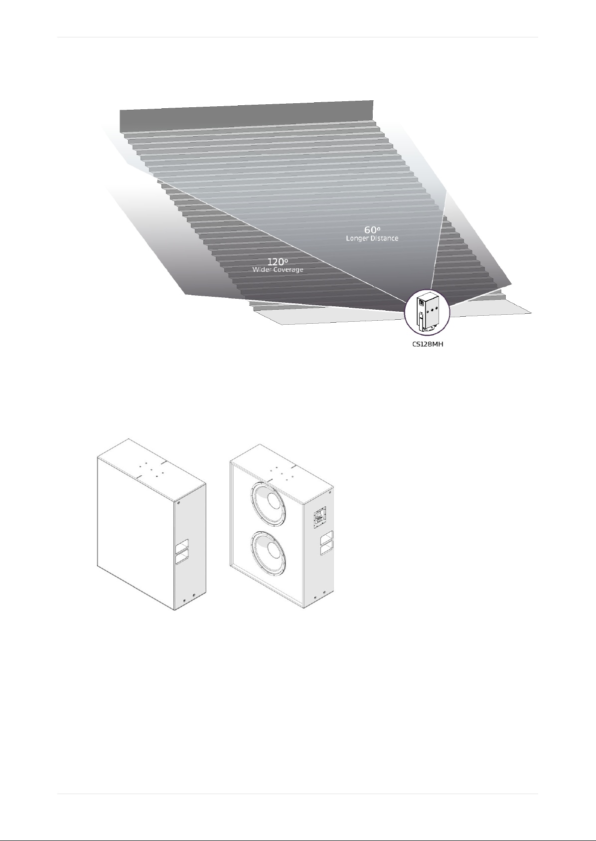
• The close spacing of the woofers to each other combined with placing the pair toward the top of the
cabinet improves system vertical dispersion.
• Rubber feet on the bottom of the cabinet help with stability and isolating the cabinet from transmitting
vibration to the building structure.
• Dual side acoustical ports (one on each side of the cabinet) can be used as integrated handles to improve
safety and comfort during handling and installation.
• BKT.FLR floor bracket kit, which is available from Dolby (sold separately), enables secure installation of
the speaker system to the building structure. The kit includes two brackets and four M10 washers.
• The CS128LF attachment points are for connecting to the auditorium building structure only; they are not
intended for hanging or flying the speaker. Always adhere to local building codes in your region.
• The advanced input plate features a high-current, spring-loaded terminal block, which enables quick
installation with no crimp tools or spade lugs needed, vastly simplifying installation.
2.4 Dolby Speaker System 128 wire selection
This section can assist you in selecting the correct wire gauge.
Typically, no more than 0.5 dB ( or 11%) of power should be lost in the cabling. The Dolby Speaker System
128 connectors accept an American Wire Gauge (AWG) of 18 AWG to 6 AWG (1 mm2 – 16 mm2). Typically, a
wire gauge of 16 AWG to 12 AWG (1.5 mm2 – 4 mm2) is recommended. The following sections provide basic
information regarding the Dolby Speaker System 128 input plates, choosing between the two modes of
operation, installing the wiring, and detailed information regarding speaker operating modes.
Note: The input terminals are marked with indicators to show the polarity. Per International
Electrotechnical Commission (IEC) standards, a positive voltage on the positive marked input results
in the transducers moving outward You must verify the positive and negative markings for each
respective product. Always tie the cable down to the available hardware to minimize any buzzing or
pullouts. If possible, aer wiring is completed, play sound through the speaker to identify any
connection issues, buzzing, or rattling.
2.5 Dolby Speaker System 128 installation information
In a typical auditorium, Dolby Speaker System 128 is installed behind the screen, with the acoustic center of
the speaker located two-thirds of the distance from the bottom of the screen.
The placement of the speakers behind the screen should follow guidance found in Dolby Atmos
Specifications for cinema, or industry standard guidance in the case of a 7.1 screen. To improve localization
and smooth pan-throughs, larger cinemas can benefit by adding le-center and right-center screen speakers.
You may need to build a screen platform to position the speaker system to the correct height. A screen
platform must be secured to the building structure. You must consult a licensed professional engineer
regarding design and construction of a screen platform.
Caution: Design and construction of a screen platform must be performed by a qualified, licensed,
and insured professional in accordance with all laws, rules, and regulations applicable to the
installation site. Failure to do so could result in serious personal injury or even death.
Dolby Speaker System 128 wire selection
Dolby Speaker System 128 Owner's Manual 9
8800293 Issue 2 27 October 2021

Figure 5: Typical auditorium installation
The elevation of the speaker system should be located with the acoustic center of the horn positioned
exactly two-thirds the distance from the bottom of the screen. The acoustic center of the speaker system is
1.6 m (63 inches) above the building structure from which it is secured. See Figure 6.
Introduction to Dolby Speaker System 128
Dolby Speaker System 128 Owner's Manual 10
8800293 Issue 2 27 October 2021

Figure 6: Dolby Speaker System 128 acoustic center
The Dolby Speaker System 128 is designed to be placed as close to the screen surface as possible with a
minimum distance of 5-7 cm. This minimizes high-frequency reflections (screen loss) but does not locate the
speaker too close to the screen. When aiming the system, angling of the CS128MH may require that the
speaker system be set back from the screen to accommodate proper tilting and aiming.
Dolby Speaker System 128 installation information
Dolby Speaker System 128 Owner's Manual 11
8800293 Issue 2 27 October 2021

Caution: Always be careful when moving the CS128LF or the assembled Dolby Speaker System
128, and employ at least two people when attempting any relocation of the loudspeakers, as
there is danger of tipping if the system is not secured to the building structure.
Figure 7: Dolby Speaker System 128 screen planes
GLL format files for soware simulation modeling
There are .GLL files that you can use to simulate the Dolby Speaker System 128 in acoustical simulation
soware. You can download the .GLL files at https://www.dolby.com/us/en/professional/cinema/products/
sys128.html. To run the .GLL files, use EASE or EASE Focus soware. EASE Focus soware is free, and can be
downloaded from https://focus.afmg.eu/index.php/fc-downloads-en.html.
Dolby Speaker System 128 .GLL file descriptions
•CS128LF GLL
• The file-name to create the Dolby Speaker System 128 screen channel is Dolby_CS128LF.
• For correct simulation, place the LF entry point (z axis) at the height of the CS128LF speaker cabinet
base in the auditorium.
•CS128MH GLL
• To finish the Dolby Speaker System 128 screen channel, use the Dolby_CS128MH file. The
loudspeaker entry point into the simulation is at the acoustic center of the system.
• Place the CS128MH height entry point (z axis) at 1.6 m (5.25 ) above the height entry point of the
CS128LF.GLL. The x and y axes should match the companion CS128LF.
• The CS128MH.GLL file can then pan +/-20 degrees horizontally, and tilt +/-15 degrees, independent of
the CS128LF, as it would in a typical configuration.
Introduction to Dolby Speaker System 128
Dolby Speaker System 128 Owner's Manual 12
8800293 Issue 2 27 October 2021

2.6 Additional information
Additional information about weight, blockage, and wire gauge selection is provided here:
• System weight is approximately 84.3 kg (186 lb).
• Please allow at least 11 inches (30cm) between the side port exits and any obstruction (including side
wall or bale wall construction). Blockage of the side port(s) will result in reduced low-frequency
extension and a decreased life span of the product.
• Wire gauge selection should always use industry-standard practice based on the loudspeaker rated ohms
and cable length. Typical maximum acceptable power loss is 0.5 dB, or less than 11%.
2.7 Contacting Dolby
You can contact Dolby Cinema Solutions and Support using email or regional telephone numbers. You can
also access documentation by visiting the Dolby customer portal.
Contact Dolby Cinema Solutions and Support
• Send an email to cinemasupport@dolby.com.
• Call:
Americas: +1-415-645-4900
Europe/Middle East/Africa (EMEA): +44-33-0808-7700
Asia-Pacific (APAC): +86-400-692-6780
Japan: +81-3-4520-9798
Access documentation
Visit https://customer.dolby.com.
Submit feedback about this documentation
Send an email to documentation@dolby.com.
Additional information
Dolby Speaker System 128 Owner's Manual 13
8800293 Issue 2 27 October 2021

3
Assembling the Dolby Speaker System 128
You will need to secure the CS128LF to the building structure, and then install the CS128MH onto the
CS128LF.
Note: BKT.FLR floor brackets are available from Dolby (sold separately) to secure the
speaker system to the building structure. When using the BKT.FLR brackets, installer must
supply the mounting hardware necessary to secure the speaker system to the building
structure. The holes in the bracket are sized for M10 or 3/8- inch bolts.
Caution: Vibration from this type of speaker system is high and may cause cabinets to
shi. Failure to secure the bottom speaker cabinet to the building structure may result in
the system tipping or falling, which may cause damage or injury.
Caution: Dolby disclaims any liability, including damage or injury, for the use of non-
Dolby supplied mounting hardware, supports, and brackets. Any modification to the
speaker system (for example, mounting by drilling holes into the speaker system) will
render the product warranty null and void.
The list below is an outline of this chapter:
•Securing the CS128LF
•Installing the CS128MH onto the CS128LF
•Aiming the Dolby Speaker System 128
•Working with electrical components
•Connecting and configuring the CS128MH
•Connecting and configuring the CS128LF
Assembling the Dolby Speaker System 128
Dolby Speaker System 128 Owner's Manual 14
8800293 Issue 2 27 October 2021

3.1 Securing the CS128LF
It is required that the speaker system is secured to the building structure.
About this task
The following tools are needed to secure the Dolby CS128LF:
• 6 mm hex driver or wrench
• BKT.FLR brackets
• Installer-provided serviceable thread-locking compound (recommended)
• Installer-provided acoustic or non-hardening caulking (recommended)
Procedure
1. Determine the proper placement of the system.
Note: Check with local building codes, and always refer the installation to a qualified professional.
2. Remove the four M10 bolts from the bottom sides of the CS128LF speaker cabinet, as shown in the
following figure. These bolts are pre-installed in the CS128LF cabinet.
3. Reinstall the M10 bolts with the M10 washers, included with the BKT.FLR kit, securing the BKT.FLR
brackets, and then tighten the M10 bolts to 12 Nm (8.9 -lb, 106 in-lb).
4. Secure the CS128LF to the building structure with installer provided mounting hardware.
Note: Proper selection and installation of mounting hardware is the exclusive responsibility of the
installer. We recommend using M10 bolts and a serviceable thread-locking compound (for
example, Loctite 243). We also recommend applying acoustic or other non-hardening caulking to
the bottom side of the bracket to isolate speaker vibration from the building structure.
Caution: Vibration from this type of speaker system is high and may cause cabinets to shi.
Failure to secure the bottom speaker cabinet to the building structure may result in the speaker
system tipping or falling, which may cause damage or injury.
Caution: Dolby disclaims any liability, including damage or injury, for the use of non-Dolby
supplied mounting hardware, supports, and brackets. Any modification to the speaker system (for
example, mounting by drilling holes into the speaker system) will render the product warranty null
and void.
Attention: The Dolby Speaker System 128 was designed to be placed as close to the screen as
possible, within 5-7 cm. When aiming the system, angling of the CS128MH may require that the
speaker system be set back from the screen to accommodate proper tilting and aiming
Securing the CS128LF
Dolby Speaker System 128 Owner's Manual 15
8800293 Issue 2 27 October 2021

Figure 8: Securing the CS128LF
Assembling the Dolby Speaker System 128
Dolby Speaker System 128 Owner's Manual 16
8800293 Issue 2 27 October 2021

3.2 Installing the CS128MH onto the CS128LF
Use the information provided in this section to install the CS128MH onto the CS128LF.
About this task
The following tools are needed to secure the Dolby CS128LF:
• 6 mm hex driver or wrench
Procedure
1. Remove the five M10 bolts from the top of CS128LF low-frequency cabinet.
2. Place the provided yoke onto the top of the CS128LF, and then reinstall the five M10 bolts (see Figure 9).
3. It is recommended to perform the horizontal aiming process at this point.
4. Fully tighten the M10 bolts.
Optionally, the M10 bolts can be loosely installed and tightened later as discussed in Aiming the Dolby
Speaker System 128 on page 18.
Figure 9: Mount yoke to top of CS128LF low-frequency cabinet
5. Install the two M10 bolts supplied with the CS128MH mounting hardware bag into the two side mounting
locations on the CS128MH cabinet.
The bolts must remain loose enough to allow the cabinet to slide into the yoke as described in step 6 (see
the following figure for M10 yoke mounting locations).
Installing the CS128MH onto the CS128LF
Dolby Speaker System 128 Owner's Manual 17
8800293 Issue 2 27 October 2021

Figure 10: Installing M10 Bolts to side locations on CS128MH
6. Carefully li the CS128MH, and then insert into the mounting yoke such that the M10 bolts (inserted in
step 5) seat into the le and right cradles located at the top of the yoke attached to the CS128LF.
7. Install and tighten the two M5 set screws and washers supplied with the CS128MH mounting hardware
bag into the two side mounting locations on the CS128MH cabinet.
Caution: Always be careful when moving the CS128LF or the assembled Dolby Speaker System
128, and employ at least two people when attempting any relocation of the loudspeakers, as there
is danger of tipping if the system is not secured to the building structure.
3.3 Aiming the Dolby Speaker System 128
Use the information provided in this section to aim the Dolby Speaker System 128 for precise sound
distribution.
About this task
The following tools are needed to secure the Dolby CS128LF:
• 6 mm hex driver or wrench
• 3mm hex driver or wrench
Note: If a laser pointer will be used for aiming, the laser pointer must be provided by the installer.
Procedure
1. Aer assembling the Dolby Speaker System 128, adjust the speaker horizontal axis by rotating the
CS128MH on the cabinet.
The angle adjustment range is +/- 20 degrees from the center, as shown on the provided decal stickers.
Assembling the Dolby Speaker System 128
Dolby Speaker System 128 Owner's Manual 18
8800293 Issue 2 27 October 2021

Figure 11: Adjust CS128MH horizontal axis
Figure 12: Vertical and horizontal aiming guide
2. Aim the CS128MH toward the theater Reference Listening Position (RLP).
If a laser pointer is used to assist in the horizontal aiming process:
a. Place the laser pointer on the outside le or right side of the CS128MH enclosure.
b. Align the laser with the vertical plane of the enclosure.
c. Adjust the horizontal angle of the CS128MH until the laser is directed at the RLP horizontal plane.
Aiming the Dolby Speaker System 128
Dolby Speaker System 128 Owner's Manual 19
8800293 Issue 2 27 October 2021

Figure 13: Laser Pointer Positioning During Horizontal Aiming
3. Tighten the M10 bolts to 4 Nm (2.95 -lb, 35.4 in-lb), so the horizontal adjustment is locked in place.
4. Loosen the M10 vertical angle adjustment points on the side of the CS128MH and tilt the cabinet to aim
the CS128MH toward the theater RLP. The angle adjustment range is +15/-15 degrees.
If a laser pointer is used to assist in the vertical aiming process:
a. Place the laser pointer on the top of the CS128MH enclosure.
b. Align the laser with the vertical plane of the enclosure.
c. Adjust the vertical angle of the CS128MH until the laser is directed at the RLP vertical plane.
Assembling the Dolby Speaker System 128
Dolby Speaker System 128 Owner's Manual 20
8800293 Issue 2 27 October 2021
Table of contents
Other Dolby Laboratories Speakers manuals
Popular Speakers manuals by other brands

REVELL
REVELL Performa S30 manual

musikelectronic geithain
musikelectronic geithain TS35 Instructions for installation and use

AudioSource
AudioSource AE5C installation manual

Bose Professional
Bose Professional EdgeMax EM90 installation guide

MTX
MTX Thunder AXE TXC4-1 owner's manual

Galaxy Audio
Galaxy Audio HS4 quick start guide