Dolmar AC3611 User manual

AC3611
EN Cordless Multi Function
Power Head INSTRUCTION MANUAL 5
FR
Moteur Multi-Fonctions Sans Fil
MANUEL D’INSTRUCTIONS 13
DE Multifunktions-Antrieb BETRIEBSANLEITUNG 22
IT Testa motorizzata
multifunzione a batteria ISTRUZIONI PER L’USO 31
NL Multifunctioneel
accuaandrijfsysteem GEBRUIKSAANWIJZING 40
ES Herramienta Multifuncional
Inalámbrica MANUAL DE
INSTRUCCIONES 49
PT
FERRAMENTA
MULTIFUNCIONAL A BATERIA
MANUAL DE INSTRUÇÕES 58
DA
Akku erfunktions motorhoved
BRUGSANVISNING 66
EL Φορητή πολυλειτουργική
ηλεκτρική κεφαλή ΕΓΧΕΙΡΙΔΙΟ ΟΔΗΓΙΩΝ 74
TR Kablosuz Çok Fonksiyonlu
Akülü Kafa KULLANMA KILAVUZU 83

2
1
89
10 11
3
4
5
6
7
12
Fig.1
2
1
3
Fig.2
1
2
Fig.3
1
Fig.4
2
1
Fig.5
1
Fig.6
1
Fig.7
2

4
2
3
1
3
5
Fig.8
1
2
Fig.9
1
Fig.10
1
2
3
Fig.11
1
Fig.12
Fig.12
3
1
2
Fig.13
1
2
Fig.14
21
Fig.15
3

1
2
Fig.16
1
Fig.17
1
2
Fig.18
1
Fig.19
4

5ENGLISH
ENGLISH (Original instructions)
SPECIFICATIONS
Model: AC3611
No load speed
(without attachment) Low 0 - 5,700 min-1
Medium 0 - 8,200 min-1
High 0 - 9,700 min-1
Overall length 1,011 mm
Rated voltage D.C. 36 V
Net weight 4.1 kg - 11.9 kg
• Duetoourcontinuingprogramofresearchanddevelopment,thespecicationshereinaresubjecttochange
without notice.
• Specicationsmaydifferfromcountrytocountry.
• Theweightmaydifferdependingontheattachment(s),includingthebatterycartridge.Thelightestandheavi-
estcombination,accordingtoEPTA-Procedure01/2014,areshowninthetable.
Applicable battery cartridge
BL1815N/BL1820/BL1820B/BL1830/BL1830B/BL1840/BL1840B/BL1850/BL1850B/BL1860B
• Someofthebatterycartridgeslistedabovemaynotbeavailabledependingonyourregionofresidence.
WARNING: Only use the battery cartridges listed above.Useofanyotherbatterycartridgesmaycause
injuryand/orre.
No load speed with attachment
Model Rotation speed
Low Medium High
BC-AC,EM401MP 0 - 4,200 min-1 0 - 6,000 min-1 0 - 7,100 min-1
EM404MP,EM406MP 0 - 3,500 min-1 0 - 5,000 min-1 0 - 6,000 min-1
HT-CS 1, HT-CS 2, HT-CS 3,
EN401MP,EN410MP,EN420MP 0 - 2,400 spm 0 - 3,400 spm 0 - 4,000 spm
PS-CS1,EY401MP(chainspeed) 0-12m/s 0-17m/s 0-20m/s
MC-CS,KR400MP 0 - 160 min-1 0 - 230 min-1 0 - 280 min-1
MC-CS1,KR401MP 0 - 130 min-1 0 - 190 min-1 0 - 230 min-1
PE-CS,EE400MP 0 - 2,800 min-1 0 - 4,000 min-1 0 - 4,700 min-1
CH-CS,EJ400MP 0 - 1,600 min-1 0 - 2,300 min-1 0 - 2,800 min-1
MB-CS,BR400MP 0 - 130 min-1 0 - 190 min-1 0 - 230 min-1
MW-CS,SW400MP 0 - 130 min-1 0 - 190 min-1 0 - 230 min-1
Approved attachment
Type Model
Brushcutter attachment BC-AC,EM401MP,EM404MP
String trimmer attachment EM406MP
Hedge trimmer attachment HT-CS1,HT-CS2,EN401MP,EN410MP
Ground trimmer attachment HT-CS3,EN420MP
Polesawattachment PS-CS1,EY401MP
Cultivator attachment MC-CS,MC-CS1,KR400MP,KR401MP
Edgerattachment PE-CS,EE400MP
Coffee harvester attachment CH-CS,EJ400MP
Shaft extension attachment SE-CS,LE400MP
Powerbrushattachment MB-CS,BR400MP
Powersweepattachment MW-CS,SW400MP

6ENGLISH
Symbols
Thefollowingshowthesymbolsusedfortheequipment.
Besurethatyouunderstandtheirmeaningbeforeuse.
Read instruction manual.
Take particular care and attention.
Do not expose to moisture.
Ni-MH
Li-ion
OnlyforEUcountries
Donotdisposeofelectricequipmentor
batterypacktogetherwithhouseholdwaste
material!InobservanceoftheEuropean
Directives,onWasteElectricandElectronic
EquipmentandBatteriesandAccumulators
andWasteBatteriesandAccumulators
and their implementation in accordance
withnationallaws,electricequipmentand
batteriesandbatterypack(s)thathave
reachedtheendoftheirlifemustbecol-
lectedseparatelyandreturnedtoanenvi-
ronmentallycompatiblerecyclingfacility.
Intended use
This cordless multi function power head is intended for
driving an approved attachment listed in the section
"SPECIFICATIONS"ofthisinstructionmanual.Never
use the unit for the other purpose.
WARNING: Read the instruction manual of
the attachment as well as this instruction manual
before using.Failuretofollowthewarningsand
instructionsmayresultseriousinjury.
Noise
Attachment Sound pressure level average Sound power level average Applicable
standard
LPA (dB (A)) Uncertainty K
(dB (A)) LWA (dB (A)) Uncertainty K
(dB (A))
BC-AC,EM401MP
(asabrushcutter) 78.5 1.0 90.2 1.5 EN11806
BC-AC,EM401MP
(as a string trimmer) Nyloncuttinghead 84.3 0.6 93.3 1.6 EN50636
Plasticblade 77.0 1.7 88.5 1.8 EN50636
EM404MP(asabrushcutter) 82.5 2.2 93.3 2.9 EN11806
EM404MP
(as a string trimmer) Nyloncuttinghead 84.7 2.3 92.8 1.6 EN50636
Plasticblade 76.0 1.8 87.7 1.5 EN50636
EM406MP Nyloncuttinghead 84.7 2.5 93.5 2.2 EN50636
Plasticblade 77.0 1.9 85.6 2.0 EN50636
HT-CS1,EN401MP 83.7 1.2 92.6 0.7 ISO10517
HT-CS1+SE-CS
EN401MP+LE400MP 83.7 1.3 92.8 1.1 ISO10517
HT-CS2,EN410MP 80.2 1.9 88.2 2.2 ISO10517
HT-CS2+SE-CS
EN410MP+LE400MP 78.9 1.7 88.3 2.7 ISO10517
HT-CS3,EN420MP 84.0 0.8 94.0 0.7 ISO10517
PS-CS1,EY401MP 92.5 1.4 101.9 1.4 ISO11680
PS-CS1+SE-CS
EY401MP+LE400MP 86.6 1.0 101.2 1.0 ISO11680
MC-CS,KR400MP 76.7 2.2 84.2 1.0 EN709
MC-CS1,KR401MP 73.1 1.4 84.2 1.8 EN709
PE-CS,EE400MP 74.8 1.5 88.2 2.6 ISO11789
CH-CS,EJ400MP 87.4 1.4 94.5 1.3 ISO10517
CH-CS+SE-CS
EJ400MP+LE400MP 85.6 1.0 95.5 1.3 ISO10517
MB-CS,BR400MP 79.5 0.9 89.0 0.7 EN60335
MW-CS,SW400MP 80.1 1.8 88.8 0.7 EN60335
• Evenifthesoundpressurelevellistedaboveis80dB(A)orless,thelevelunderworkingmayexceed80dB
(A).Wearearprotection.

7ENGLISH
Vibration
Attachment Left handle (Front grip) Right handle (Rear grip) Applicable
standard
ah (m/s2)Uncertainty K
(m/s2)ah (m/s2)Uncertainty K
(m/s2)
BC-AC,EM401MP
(asabrushcutter) 3.0 1.5 2.5 1.5 EN11806
BC-AC,EM401MP
(as a string trimmer) Nyloncuttinghead 5.0 1.5 2.5 1.5 EN50636
Plasticblade 2.5 1.5 2.5 1.5 EN50636
EM404MP(asabrushcutter) 3.0 1.5 2.5 1.5 EN11806
EM404MP
(as a string trimmer) Nyloncuttinghead 3.0 1.5 2.5 1.5 EN50636
Plasticblade 2.5 1.5 2.5 1.5 EN50636
EM406MP Nyloncuttinghead 2.5 1.5 2.5 1.5 EN50636
Plasticblade 4.0 1.5 2.5 1.5 EN50636
HT-CS1,EN401MP 5.5 1.5 3.5 1.5 ISO10517,
EN60745
HT-CS1+SE-CS
EN401MP+LE400MP 5.5 1.5 4.0 1.5 ISO10517,
EN60745
HT-CS2,EN410MP 4.0 1.5 2.5 1.5 ISO10517,
EN60745
HT-CS2+SE-CS
EN410MP+LE400MP 4.5 1.5 2.5 1.5 ISO10517,
EN60745
HT-CS3,EN420MP 6.5 1.5 4.0 1.5 ISO10517
PS-CS1,EY401MP 2.5 1.5 2.5 1.5 ISO11680
PS-CS1+SE-CS
EY401MP+LE400MP 5.5 1.5 2.5 1.5 ISO11680
MC-CS,KR400MP 2.5 1.5 2.5 1.5 EN709
MC-CS1,KR401MP 2.5 1.5 2.5 1.5 EN709
PE-CS,EE400MP 2.5 1.5 2.5 1.5 ISO11789
CH-CS,EJ400MP 4.0 1.5 3.0 1.5 ISO10517
CH-CS+SE-CS
EJ400MP+LE400MP 4.5 1.5 3.0 1.5 ISO10517
MB-CS,BR400MP 2.5 1.5 2.5 1.5 EN60335
MW-CS,SW400MP 2.6 1.5 2.6 1.5 EN60335
NOTE:Thedeclaredvibrationtotalvalue(s)hasbeenmeasuredinaccordancewithastandardtestmethodand
maybeusedforcomparingonetoolwithanother.
NOTE:Thedeclaredvibrationtotalvalue(s)mayalsobeusedinapreliminaryassessmentofexposure.
WARNING: The vibration emission during actual use of the power tool can differ from the declared
value(s) depending on the ways in which the tool is used especially what kind of workpiece is processed.
WARNING: Be sure to identify safety measures to protect the operator that are based on an estimation
of exposure in the actual conditions of use (taking account of all parts of the operating cycle such as the
times when the tool is switched off and when it is running idle in addition to the trigger time).
EC Declaration of Conformity
For European countries only
TheECdeclarationofconformityisincludedasAnnexA
to this instruction manual.

8ENGLISH
SAFETY WARNINGS
General power tool safety warnings
WARNING: Read all safety warnings, instruc-
tions, illustrations and specications provided
with this power tool.Failuretofollowallinstructions
listedbelowmayresultinelectricshock,reand/or
seriousinjury.
Save all warnings and instruc-
tions for future reference.
Theterm"powertool"inthewarningsreferstoyour
mains-operated(corded)powertoolorbattery-operated
(cordless) power tool.
Important safety instructions for
battery cartridge
1. Before using battery cartridge, read all instruc-
tions and cautionary markings on (1) battery
charger, (2) battery, and (3) product using
battery.
2. Do not disassemble battery cartridge.
3. If operating time has become excessively
shorter, stop operating immediately. It may
result in a risk of overheating, possible burns
and even an explosion.
4. If electrolyte gets into your eyes, rinse them
out with clear water and seek medical atten-
tion right away. It may result in loss of your
eyesight.
5. Do not short the battery cartridge:
(1) Do not touch the terminals with any con-
ductive material.
(2) Avoid storing battery cartridge in a con-
tainer with other metal objects such as
nails, coins, etc.
(3) Do not expose battery cartridge to water
or rain.
A battery short can cause a large current
ow, overheating, possible burns and even a
breakdown.
6. Do not store the tool and battery cartridge in
locations where the temperature may reach or
exceed 50 °C (122 °F).
7. Do not incinerate the battery cartridge even if
it is severely damaged or is completely worn
out. The battery cartridge can explode in a re.
8. Be careful not to drop or strike battery.
9. Do not use a damaged battery.
10. The contained lithium-ion batteries are subject
to the Dangerous Goods Legislation require-
ments.
Forcommercialtransportse.g.bythirdparties,
forwardingagents,specialrequirementonpack-
agingandlabelingmustbeobserved.
Forpreparationoftheitembeingshipped,consult-
inganexpertforhazardousmaterialisrequired.
Pleasealsoobservepossiblymoredetailed
national regulations.
Tape or mask off open contacts and pack up the
batteryinsuchamannerthatitcannotmove
around in the packaging.
11. Follow your local regulations relating to dis-
posal of battery.
12. Use the batteries only with the products
specied by Makita.Installingthebatteriesto
non-compliantproductsmayresultinare,exces-
siveheat,explosion,orleakofelectrolyte.
SAVE THESE INSTRUCTIONS.
CAUTION: Only use genuine Makita batteries.
Useofnon-genuineMakitabatteries,orbatteriesthat
havebeenaltered,mayresultinthebatterybursting
causingres,personalinjuryanddamage.Itwill
alsovoidtheMakitawarrantyfortheMakitatooland
charger.
Tips for maintaining maximum
battery life
1. Charge the battery cartridge before completely
discharged. Always stop tool operation and
charge the battery cartridge when you notice
less tool power.
2. Never recharge a fully charged battery car-
tridge. Overcharging shortens the battery
service life.
3. Charge the battery cartridge with room tem-
perature at 10 °C - 40 °C (50 °F - 104 °F). Let
a hot battery cartridge cool down before
charging it.
4. Charge the battery cartridge if you do not use
it for a long period (more than six months).
PARTS DESCRIPTION
►Fig.1
1Batterycartridge 2Lock-off lever 3Switch trigger 4Hanger
5Handle 6Releasebutton 7Barrier(countryspecic) 8Speed indicator
9Powerlamp 10 Mainpowerbutton 11 Reversebutton 12 Shoulder harness

9ENGLISH
FUNCTIONALDESCRIPTION
WARNING: Always be sure that the tool is
switched off and the battery cartridge is removed
before adjusting or checking function on the tool.
Failuretoswitchoffandremovethebatterycartridge
mayresultinseriouspersonalinjuryfromaccidental
start-up.
Installing or removing battery cartridge
CAUTION: Always switch off the tool before
installing or removing of the battery cartridge.
CAUTION: Hold the tool and the battery car-
tridge rmly when installing or removing battery
cartridge.Failuretoholdthetoolandthebattery
cartridgermlymaycausethemtoslipoffyourhands
andresultindamagetothetoolandbatterycartridge
andapersonalinjury.
►Fig.2: 1. Red indicator 2. Button 3.Batterycartridge
Toremovethebatterycartridge,slideitfromthetool
whileslidingthebuttononthefrontofthecartridge.
Toinstallthebatterycartridge,alignthetongueonthe
batterycartridgewiththegrooveinthehousingandslip
itintoplace.Insertitallthewayuntilitlocksinplace
withalittleclick.Ifyoucanseetheredindicatoronthe
uppersideofthebutton,itisnotlockedcompletely.
CAUTION: Always install the battery cartridge
fully until the red indicator cannot be seen. If not,
itmayaccidentallyfalloutofthetool,causinginjuryto
youorsomeonearoundyou.
CAUTION: Do not install the battery cartridge
forcibly.Ifthecartridgedoesnotslideineasily,itis
notbeinginsertedcorrectly.
Tool / battery protection system
Thetoolisequippedwithatool/batteryprotectionsys-
tem.Thissystemautomaticallycutsoffpowertothe
motortoextendtoolandbatterylife.Thetoolwillauto-
maticallystopduringoperationifthetoolorbatteryis
placed under one of the following conditions:
Status Indicator lamps
On Off Blinking
Overload
Overheat
Over
discharge
Overload protection
Ifthetoolisoverloadedbyentangledweedsorother
debris, andthemiddleindicatorsstartblinkingand
thetoolautomaticallystops.
In this situation, turn the tool off and stop the application
thatcausedthetooltobecomeoverloaded.Thenturn
the tool on to restart.
Overheat protection for tool or battery
Whenaoverheatingoccurs,allspeedindicatorsblink.
Iftheoverheatingoccurs,thetoolstopsautomatically.
Letthetooland/orbatterycooldownbeforeturningthe
tool on again.
Overdischarge protection
Whenthebatterycapacitybecomeslow,thetoolstops
automaticallyand indicatorblinks.
If the tool does not operate even when the switches are
operated,removethebatteriesfromthetoolandcharge
thebatteries.
Indicating the remaining battery capacity
Only for battery cartridges with the indicator
►Fig.3: 1. Indicator lamps 2.Checkbutton
Pressthecheckbuttononthebatterycartridgetoindi-
catetheremainingbatterycapacity.Theindicatorlamps
light up for a few seconds.
Indicator lamps Remaining
capacity
Lighted Off Blinking
75% to 100%
50% to 75%
25% to 50%
0% to 25%
Charge the
battery.
Thebattery
mayhave
malfunctioned.
NOTE: Depending on the conditions of use and the
ambienttemperature,theindicationmaydifferslightly
fromtheactualcapacity.
Main power switch
WARNING: Always turn off the main power
switch when not in use.
Tostandbythetool,pressthemainpowerbuttonuntil
the main power lamp lights up. To turn off, press the
mainpowerbuttonagain.
►Fig.4: 1.Mainpowerbutton

10 ENGLISH
NOTE:Themainpowerlampbrinksiftheswitch
triggerispulledunderunoperatableconditions.The
lampblinksifyouturnonthemainpowerswitchwhile
holding down the lock-off lever and the switch trigger
NOTE:Thistoolemploystheautopower-offfunction.
To avoid unintentional start up, the main power switch
willautomaticallyshutdownwhentheswitchtrigger
is not pulled for a certain period after the main power
switch is turned on.
Switch action
WARNING: For your safety, this tool is
equipped with lock-off lever which prevents the
tool from unintended starting. NEVER use the tool
if it runs when you simply pull the switch trigger
without pressing the lock-off lever. Return the
tool to our authorized service center for proper
repairs BEFORE further usage.
WARNING: NEVER tape down or defeat pur-
pose and function of lock-off lever.
CAUTION: Before installing the battery car-
tridge into the tool, always check to see that the
switch trigger actuates properly and returns to
the "OFF" position when released.
NOTICE: Do not pull the switch trigger hard with-
out pressing the lock-off lever. This can cause
switch breakage.
Topreventtheswitchtriggerfrombeingaccidentally
pulled, a lock-off lever is provided.
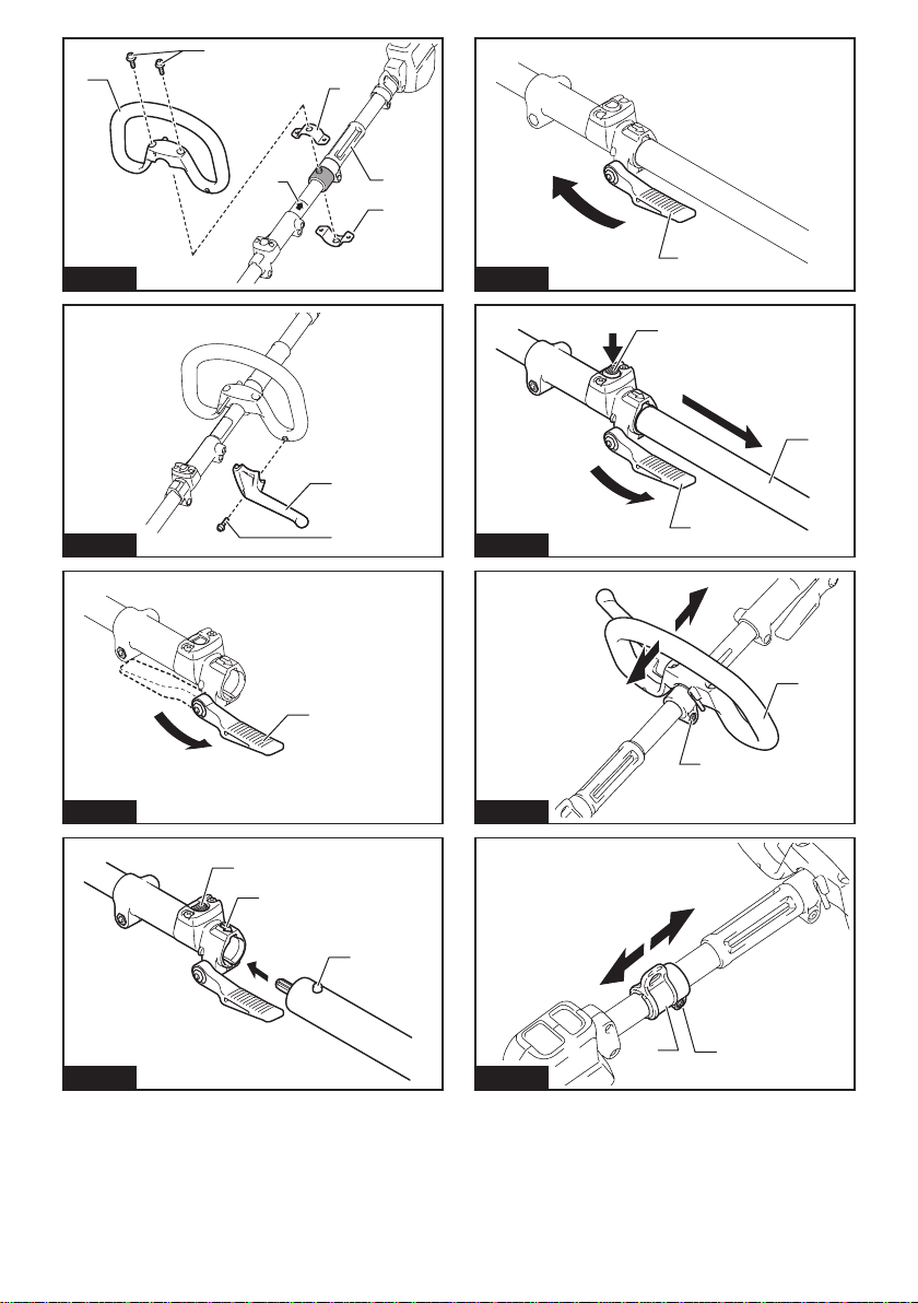
►Fig.5: 1. Lock-off lever 2. Switch trigger
To start the tool, turn on the main power switch and
graspthehandle(thelock-offleverisreleasedbythe
grasp) and then pull the switch trigger. Tool speed is
increasedbyincreasingthepressureontheswitch
trigger. To stop the tool, release the switch trigger.
Speed adjusting
Youcanadjustthetoolspeedbytappingthemain
powerbutton.
Eachtimeyoutapthemainpowerbutton,thelevelof
speed will change.
►Fig.6: 1.Mainpowerbutton
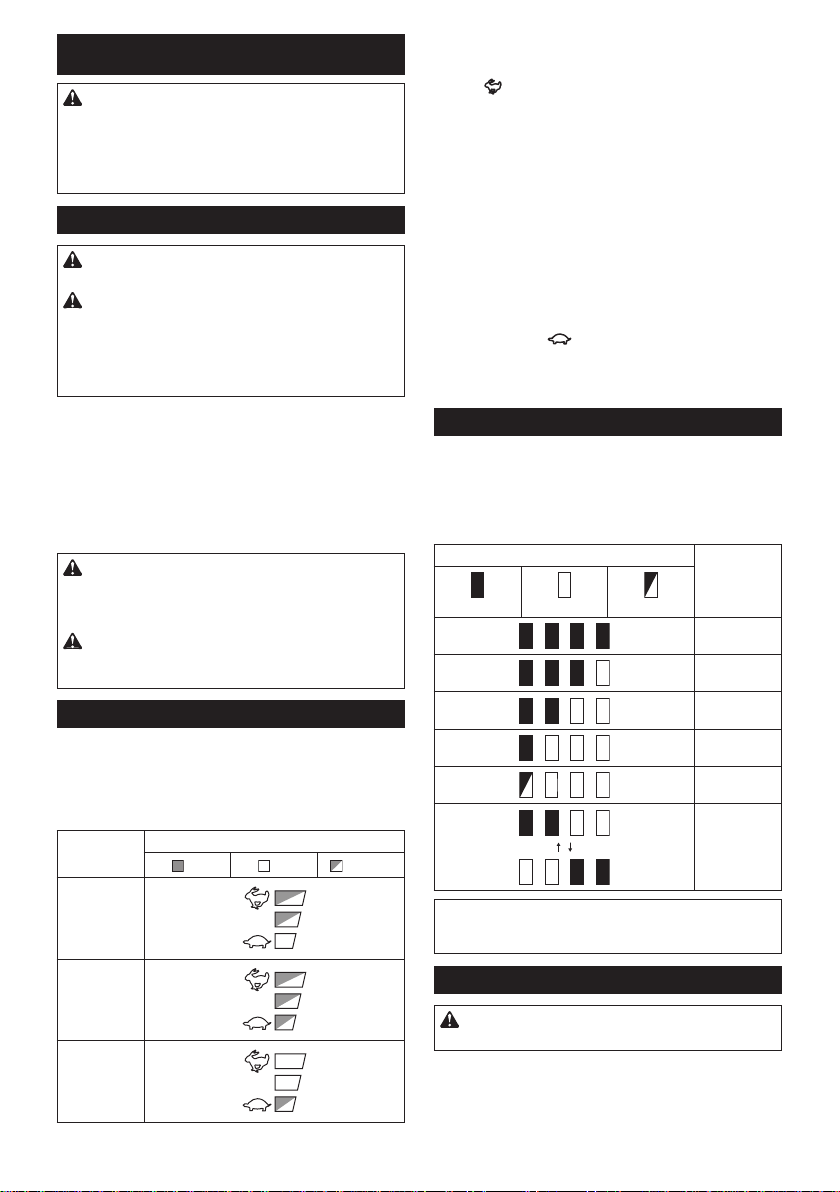
Indicator Mode
High
Medium
Low
Reverse button for debris removal
WARNING: Switch off the tool and remove
the battery cartridge before you remove entan-
gled weeds or debris which the reverse rotation
function can not remove.Failuretoswitchoffand
removethebatterycartridgemayresultinserious
personalinjuryfromaccidentalstart-up.
Thistoolhasareversebuttontochangethedirectionofrotation.
Itisonlyforremovingweedsanddebrisentangledinthetool.
Toreversetherotation,tapthereversebuttonandpull
the trigger when the tool’s head is stopped. The power
lampstartsblinking,andthetool'sheadrotatesin
reversedirectionwhenyoupulltheswitchtrigger.
To return to regular rotation, release the trigger and wait
untilthetool'sheadstops.
►Fig.7: 1.Reversebutton
NOTE:
Duringthereverserotation,thetooloperatesonly
forashortperiodoftimeandthenautomaticallystops.
NOTE: Once the tool is stopped, the rotation returns
toregulardirectionwhenyoustartthetoolagain.
NOTE:Ifyoutapthereversebuttonwhilethetool's
headisstillrotating,thetoolcomestostopandtobe
readyforreverserotation.
Electronic torque control function
Thetoolelectronicallydetectsasuddendropinthe
rotationspeedwhichmaycauseakickback.Inthis
situation,thetoolautomaticallystopstopreventfurther
rotation of cutting tool. To restart the tool, release the
switch trigger. Clear the cause of sudden drop in the
rotation speed and then turn the tool on.
NOTE: This function is not a preventive measure for
kickbacks.
ASSEMBLY
WARNING: Always be sure that the tool is
switched off and battery cartridge is removed
before carrying out any work on the tool.Failureto
switchoffandremovethebatterycartridgemayresult
inseriouspersonalinjuryfromaccidentalstart-up.
WARNING: Never start the tool unless it is
completely assembled. Operation of the tool in a
partiallyassembledstatemayresultinseriousper-
sonalinjuryfromaccidentalstart-up.
Mounting the handle
Attachthehandlewithsuppliedclampsandbolts.Make
surethatthehandleislocatedbetweenthespacerand
the arrow mark. Do not remove or shrink the spacer.
►Fig.8: 1. Handle 2.Hexsocketbolt3. Clamp
4. Spacer 5.Arrowmark
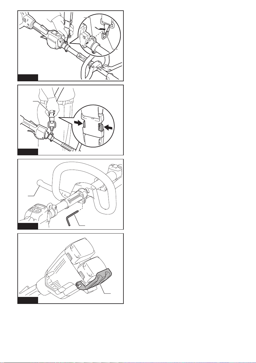
Attachthebarrier(countryspecic)tothehandleusingthescrew
onthebarrier.Onceassembled,donotremovethebarrier.
►Fig.9: 1. Barrier 2. Screw

11 ENGLISH
Mounting the attachment pipe
CAUTION: Always check that the attachment
pipe is secured after installation. Improper instal-
lationmaycausetheattachmentfallingofffromthe
powerunitandcausepersonalinjury.
Mount the attachment pipe to the power unit.
1. Turn the lever toward the attachment.
►Fig.10: 1. Lever
2. Alignthepinwiththearrowmarkandinsertthe
attachmentpipeuntilthereleasebuttonpopsup.
►Fig.11: 1.Releasebutton2.Arrowmark3.Pin
3. Turn the lever toward the power unit.
►Fig.12: 1. Lever
Make sure that the surface of the lever is parallel to the pipe.
To remove the pipe, turn the lever toward the attach-
ment and pull the pipe out while pressing down the
releasebutton.
►Fig.13: 1.Releasebutton2. Lever 3.Pipe
Adjusting the handle/hanger position
Adjustthehandleandhangerpositiontoobtainconfort-
ablehandlingofthetool.
Loosenthehexsocketheadboltonthehandle.Move
thehandletoacomfortableworkingpositionandthen
tightenthebolt.
►Fig.14: 1. Handle 2.Hexsocketheadbolt
Loosenthehexsocketheadboltonthehanger.Move
thehangertoacomfortableworkingpositionandthen
tightenthebolt.
►Fig.15: 1.Hexsocketheadbolt2. Hanger
Attaching shoulder harness
WARNING: Be extremely careful to maintain
control of the tool at all times. Do not allow the
tool to be deected toward you or anyone in the
work vicinity.Failuretokeepcontrolofthetool
couldresultinseriousinjurytothebystanderandthe
operator.
CAUTION: Always use the shoulder harness
attached. Before operation, adjust the shoulder
harness according to the user size to prevent
fatigue.
Puttheshoulderharnessonyourleftshoulderbyput-
tingyourheadandrightarmthroughit.Keepthetoolon
yourrightside.
Afterputtingtheshoulderharness,attachittothetool
byconnectingthebucklesprovidedonboththetool
hookandtheharness.Besurethatthebucklesclick
andlockcompletelyinplace.
Adjustthestraptothesuitablelengthforyouroperation.
►Fig.16: 1. Hanger 2. Hook
Thebuckleisprovidedwithameansofquickrelease
whichcanbeaccomplishedbysimplysqueezingthe
sidesandthebuckle.
►Fig.17: 1. Buckle
Hex wrench storage
CAUTION: Be careful not to leave the hex
wrench inserted in the tool head. Itmaycause
injuryand/ordamagetothetool.
When not in use, store the hex wrench as illustrated to
keepitfrombeinglost.
►Fig.18: 1. Handle 2. Hex wrench
MAINTENANCE
WARNING: Always be sure that the tool is
switched off and battery cartridge is removed
before attempting to perform inspection or main-
tenance on the tool.Failuretoswitchoffandremove
thebatterycartridgemayresultinseriouspersonal
injuryfromaccidentalstart-up.
NOTICE: Never use gasoline, benzine, thinner,
alcohol or the like. Discoloration, deformation or
cracks may result.
Battery guard
WARNING: Do not remove the battery
guard. Do not use the tool with the battery guard
removed or damaged.Directimpacttothebattery
cartridgemaycausebatterymalfunctionandresult
ininjuryand/orre.Ifthebatteryguardisdeformed
ordamaged,contactyourauthorizedservicecenter
for repairs.
►Fig.19: 1.Batteryguard
TomaintainproductSAFETYandRELIABILITY,
repairs,anyothermaintenanceoradjustmentshould
beperformedbyMakita/DolmarAuthorizedorFactory
ServiceCenters,alwaysusingMakita/Dolmarreplace-
ment parts.

12 ENGLISH
TROUBLESHOOTING
Beforeaskingforrepairs,conductyourowninspectionrst.Ifyoundaproblemthatisnotexplainedinthemanual,
donotattempttodismantlethetool.Instead,askDolmarAuthorizedServiceCenters,alwaysusingDolmarreplace-
ment parts for repairs.
State of abnormality Probable cause (malfunction) Remedy
Motor does not run. Batterycartridgeisnotinstalled. Installthebatterycartridge.
Batteryproblem(undervoltage) Rechargethebattery.Ifrechargingisnoteffective,
replacebattery.
Thedrivesystemdoesnotwork
correctly.
Askyourlocalauthorizedservicecenterforrepair.
Motor stops running after a little use. Rotation is in reverse. Change the direction of rotation with the reversing
switch.
Battery'schargelevelislow. Rechargethebattery.Ifrechargingisnoteffective,
replacebattery.
Overheating. Stop using of tool to allow it to cool down.
ItdoesnotreachmaximumRPM. Batteryisinstalledimproperly. Installthebatterycartridgeasdescribedinthis
manual.
Batterypowerisdropping. Rechargethebattery.Ifrechargingisnoteffective,
replacebattery.
Thedrivesystemdoesnotwork
correctly.
Askyourlocalauthorizedservicecenterforrepair.
OPTIONAL
ACCESSORIES
CAUTION: These accessories or attachments
are recommended for use with your Dolmar tool
specied in this manual.Theuseofanyother
accessories or attachments might present a risk of
injurytopersons.Onlyuseaccessoryorattachment
for its stated purpose.
Ifyouneedanyassistanceformoredetailsregarding
theseaccessories,askyourlocalDolmarService
Center.
Referto"Approvedattachment"sectionfortheapplica-
blemodelsforthistool.
• Edgerattachment
• Brushcutter attachment
• String trimmer attachment
• Hedge trimmer attachment
• Ground trimmer attachment
• Polesawattachment
• Coffee harvester attachment
• Cultivator attachment
• Shaft extension attachment
• Powerbrushattachment
• Powersweepattachment
• Makitagenuinebatteryandcharger
NOTE:Someitemsinthelistmaybeincludedinthe
toolpackageasstandardaccessories.Theymay
differfromcountrytocountry.

13 FRANÇAIS
FRANÇAIS (Instructions originales)
SPÉCIFICATIONS
Modèle : AC3611
Vitesse à vide
(sans accessoire) Faible 0 - 5 700 min-1
Moyen 0 - 8 200 min-1
Élevé 0 - 9 700 min-1
Longueur totale 1 011 mm
Tension nominale 36 V CC
Poidsnet 4,1 kg - 11,9 kg
• Étantdonnél’évolutionconstantedenotreprogrammederechercheetdedéveloppement,lesspécications
contenuesdanscemanuelsontsujettesàmodicationsanspréavis.
• Lesspécicationspeuventvariersuivantlespays.
• Lepoidspeutêtredifférentselonlesaccessoires,notammentlabatterie.Lesassociationslapluslégèreetla
pluslourde,conformémentàlaprocédureEPTA01/2014,sontindiquéesdansletableau.
Batterie applicable
BL1815N/BL1820/BL1820B/BL1830/BL1830B/BL1840/BL1840B/BL1850/BL1850B/BL1860B
• Certainesbatteriesrépertoriéesci-dessuspeuventnepasêtredisponiblesselonlarégionoùvousrésidez.
AVERTISSEMENT : N’utilisez que les batteries répertoriées ci-dessus.L’utilisationden’importequelle
autrebatteriepeutprovoquerdesblessureset/ouunincendie.
Vitesse à vide avec accessoire
Modèle Vitesse de rotation
Faible Moyen Élevé
BC-AC,EM401MP 0 - 4 200 min-1 0 - 6 000 min-1 0 - 7 100 min-1
EM404MP,EM406MP 0 - 3 500 min-1 0 - 5 000 min-1 0 - 6 000 min-1
HT-CS 1, HT-CS 2, HT-CS 3,
EN401MP,EN410MP,EN420MP 0 - 2 400 min-1 0 - 3 400 min-1 0 - 4 000 min-1
PS-CS1,EY401MP(vitessedechaîne) 0-12m/s 0-17m/s 0-20m/s
MC-CS,KR400MP 0 - 160 min-1 0 - 230 min-1 0 - 280 min-1
MC-CS1,KR401MP 0 - 130 min-1 0 - 190 min-1 0 - 230 min-1
PE-CS,EE400MP 0 - 2 800 min-1 0 - 4 000 min-1 0 - 4 700 min-1
CH-CS,EJ400MP 0 - 1 600 min-1 0 - 2 300 min-1 0 - 2 800 min-1
MB-CS,BR400MP 0 - 130 min-1 0 - 190 min-1 0 - 230 min-1
MW-CS,SW400MP 0 - 130 min-1 0 - 190 min-1 0 - 230 min-1
Accessoire approuvé
Type Modèle
TêteDébroussailleuse BC-AC,EM401MP,EM404MP
TêteCoupeHerbe EM406MP
TêteTaille-HaieàPerche HT-CS1,HT-CS2,EN401MP,EN410MP
TêteFaucheuse HT-CS3,EN420MP
TêteÉlagueuseàPerche PS-CS1,EY401MP
Tête Moto-Bineuse MC-CS,MC-CS1,KR400MP,KR401MP
Tête Dresse-Bordures PE-CS,EE400MP
TêtePeigneVibreurPourCafé CH-CS,EJ400MP
Rallonged’Arbre SE-CS,LE400MP
Outil Balai Brosse MB-CS,BR400MP
Outil Balai Racleur MW-CS,SW400MP

14 FRANÇAIS
Symboles
Voustrouverezci-dessouslessymbolesutiliséspourl’appareil.
Veillezàcomprendreleursignicationavanttouteutilisation.
Lire le mode d’emploi.
Veuillez être prudent et rester attentif.
Ne pas exposer à l’eau.
Ni-MH
Li-ion
Uniquementpourlespayseuropéens
Nejetezpaslesappareilsélectriquesou
lesbatteriesavecvosorduresménagères!
Conformément aux directives européennes rela-
tivesauxdéchetsd’équipementsélectriqueset
électroniquesetauxpilesetaccumulateursainsi
qu’auxdéchetsdepilesetd’accumulateurset
leur mise en œuvre conformément aux lois natio-
nales,leséquipementsélectriquesetlespileset
batteriesenndeviedoiventfairel’objetd’une
collectesélectiveetêtreconésàuneusinede
recyclagerespectueusedel’environnement.
Utilisations
Cemoteurmulti-fonctionssanslestconçupour
entraînerunaccessoireapprouvédanslasection«
SPÉCIFICATIONS»decemanueld’instructions.Ne
jamaisutiliserl’unitédansunautrebut.
AVERTISSEMENT : Lire le manuel d’instruc-
tions de l’accessoire, ainsi que ce manuel d’ins-
tructions avant toute utilisation. Le non-respect
desavertissementsetdesinstructionspeutentraîner
degravesblessures.
Bruit
Accessoire Niveau de pression sonore
moyenne Niveau de puissance sonore
moyenne Norme
applicable
LPA (dB (A)) Incertitude K
(dB (A)) LWA (dB (A)) Incertitude K
(dB (A))
BC-AC,EM401MP
(commedébroussailleuse) 78,5 1,0 90,2 1,5 EN11806
BC-AC,EM401MP
(commecoupeherbe)
Têtedecoupeàlnylon
84,3 0,6 93,3 1,6 EN50636
Lameenplastique 77,0 1,7 88,5 1,8 EN50636
EM404MP(commedébroussailleuse) 82,5 2,2 93,3 2,9 EN11806
EM404MP
(commecoupeherbe)
Têtedecoupeàlnylon
84,7 2,3 92,8 1,6 EN50636
Lameenplastique 76,0 1,8 87,7 1,5 EN50636
EM406MP
Têtedecoupeàlnylon
84,7 2,5 93,5 2,2 EN50636
Lameenplastique 77,0 1,9 85,6 2,0 EN50636
HT-CS1,EN401MP 83,7 1,2 92,6 0,7 ISO10517
HT-CS1+SE-CS
EN401MP+LE400MP 83,7 1,3 92,8 1,1 ISO10517
HT-CS2,EN410MP 80,2 1,9 88,2 2,2 ISO10517
HT-CS2+SE-CS
EN410MP+LE400MP 78,9 1,7 88,3 2,7 ISO10517
HT-CS3,EN420MP 84,0 0,8 94,0 0,7 ISO10517
PS-CS1,EY401MP 92,5 1,4 101,9 1,4 ISO11680
PS-CS1+SE-CS
EY401MP+LE400MP 86,6 1,0 101,2 1,0 ISO11680
MC-CS,KR400MP 76,7 2,2 84,2 1,0 EN709
MC-CS1,KR401MP 73,1 1,4 84,2 1,8 EN709
PE-CS,EE400MP 74,8 1,5 88,2 2,6 ISO11789
CH-CS,EJ400MP 87,4 1,4 94,5 1,3 ISO10517
CH-CS+SE-CS
EJ400MP+LE400MP 85,6 1,0 95,5 1,3 ISO10517
MB-CS,BR400MP 79,5 0,9 89,0 0,7 EN60335
MW-CS,SW400MP 80,1 1,8 88,8 0,7 EN60335
• Mêmesileniveaudepressionsonoreindiquéci-dessusestinférieurouégalà80dB(A),leniveauenfonction-
nementpeutdépasser80dB(A).Portezunserre-têteantibruit.

15 FRANÇAIS
Vibration
Accessoire Poignée gauche (prise avant) Poignée droite (prise arrière) Norme
applicable
ah (m/s2)Incertitude K
(m/s2)ah (m/s2)Incertitude K
(m/s2)
BC-AC,EM401MP
(commedébroussailleuse) 3,0 1,5 2,5 1,5 EN11806
BC-AC,EM401MP
(commecoupeherbe)
Têtedecoupeàlnylon
5,0 1,5 2,5 1,5 EN50636
Lameenplastique 2,5 1,5 2,5 1,5 EN50636
EM404MP(commedébroussailleuse) 3,0 1,5 2,5 1,5 EN11806
EM404MP
(commecoupeherbe)
Têtedecoupeàlnylon
3,0 1,5 2,5 1,5 EN50636
Lameenplastique 2,5 1,5 2,5 1,5 EN50636
EM406MP
Têtedecoupeàlnylon
2,5 1,5 2,5 1,5 EN50636
Lameenplastique 4,0 1,5 2,5 1,5 EN50636
HT-CS1,EN401MP 5,5 1,5 3,5 1,5 ISO10517,
EN60745
HT-CS1+SE-CS
EN401MP+LE400MP 5,5 1,5 4,0 1,5 ISO10517,
EN60745
HT-CS2,EN410MP 4,0 1,5 2,5 1,5 ISO10517,
EN60745
HT-CS2+SE-CS
EN410MP+LE400MP 4,5 1,5 2,5 1,5 ISO10517,
EN60745
HT-CS3,EN420MP 6,5 1,5 4,0 1,5 ISO10517
PS-CS1,EY401MP 2,5 1,5 2,5 1,5 ISO11680
PS-CS1+SE-CS
EY401MP+LE400MP 5,5 1,5 2,5 1,5 ISO11680
MC-CS,KR400MP 2,5 1,5 2,5 1,5 EN709
MC-CS1,KR401MP 2,5 1,5 2,5 1,5 EN709
PE-CS,EE400MP 2,5 1,5 2,5 1,5 ISO11789
CH-CS,EJ400MP 4,0 1,5 3,0 1,5 ISO10517
CH-CS+SE-CS
EJ400MP+LE400MP 4,5 1,5 3,0 1,5 ISO10517
MB-CS,BR400MP 2,5 1,5 2,5 1,5 EN60335
MW-CS,SW400MP 2,6 1,5 2,6 1,5 EN60335
NOTE :Laoulesvaleursdevibrationtotalesdéclaréesontétémesuréesconformémentàlaméthodedetest
standard et peuvent être utilisées pour comparer les outils entre eux.
NOTE :Laoulesvaleursdevibrationtotalesdéclaréespeuventaussiêtreutiliséespourl’évaluationpréliminaire
de l’exposition.
AVERTISSEMENT : L’émission de vibrations lors de l’usage réel de l’outil électrique peut être diffé-
rente de la ou des valeurs déclarées, suivant la façon dont l’outil est utilisé, particulièrement selon le type
de pièce usinée.
AVERTISSEMENT : Les mesures de sécurité à prendre pour protéger l’utilisateur doivent être basées
sur une estimation de l’exposition dans des conditions réelles d’utilisation (en tenant compte de toutes
les composantes du cycle d’utilisation, comme par exemple le moment de sa mise hors tension, lorsqu’il
tourne à vide et le moment de son déclenchement).
Déclaration de conformité CE
Pour les pays européens uniquement
LadéclarationdeconformitéCEestfournieenAnnexe
Aàcemoded’emploi.

16 FRANÇAIS
CONSIGNES DE
SÉCURITÉ
Consignes de sécurité générales
pour outils électriques
AVERTISSEMENT : Veuillez lire les
consignes de sécurité, instructions, illustrations
et spécications qui accompagnent cet outil
électrique. Le non-respect de toutes les instructions
indiquéesci-dessouspeutentraîneruneélectrocu-
tion,unincendieet/oudegravesblessures.
Conservez toutes les mises en
garde et instructions pour réfé-
rence ultérieure.
Leterme«outilélectrique»danslesavertissements
faitréférenceàl’outilélectriquealimentéparlesecteur
(aveccordond’alimentation)ouàl’outilélectriquefonc-
tionnantsurbatterie(sanscordond’alimentation).
Consignes de sécurité importantes
pour la batterie
1. Avant d’utiliser la batterie, lisez toutes les
instructions et précautions relatives (1) au
chargeur de batterie, (2) à la batterie, et (3) au
produit utilisant la batterie.
2. Ne démontez pas la batterie.
3. Cessez immédiatement l’utilisation si le temps
de fonctionnement devient excessivement
court. Il y a risque de surchauffe, de brûlures,
voire d’explosion.
4. Si l’électrolyte pénètre dans vos yeux, rin-
cez-les à l’eau claire et consultez immédiate-
ment un médecin. Il y a risque de perte de la
vue.
5. Ne court-circuitez pas la batterie :
(1) Ne touchez les bornes avec aucun maté-
riau conducteur.
(2) Évitez de ranger la batterie dans un
conteneur avec d’autres objets métal-
liques, par exemple des clous, des pièces
de monnaie, etc.
(3) N’exposez pas la batterie à l’eau ou à la
pluie.
Un court-circuit de la batterie peut provoquer
une intensité de courant élevée, une sur-
chauffe, parfois des brûlures et même une
panne.
6. Ne rangez pas l’outil et la batterie dans un
endroit où la température risque d’atteindre ou
de dépasser 50 °C.
7. Ne jetez pas la batterie au feu même si elle est
sérieusement endommagée ou complètement
épuisée. La batterie peut exploser au contact
du feu.
8. Évitez de laisser tomber ou de cogner la
batterie.
9. N’utilisez pas la batterie si elle est
endommagée.
10. Les batteries au lithium-ion contenues sont
soumises aux exigences de la législation sur
les marchandises dangereuses.
Lors du transport commercial par des tierces
parties ou des transitaires par exemple, des exi-
gencesspéciquesenmatièred’étiquetageet
d’emballagedoiventêtrerespectées.
Pourlapréparationdel’articleexpédié,ilest
nécessaire de consulter un expert en matériau
dangereux. Veuillez également respecter les
réglementationsnationalessusceptiblesd’être
plus détaillées.
Recouvrezlescontactsexposésavecduruban
adhésifoudurubandemasquageetemballezla
batteriedetellesortequ’ellenepuissepasbouger
dansl’emballage.
11. Suivez les réglementations locales en matière
de mise au rebut des batteries.
12. Utilisez les batteries uniquement avec les
produits spéciés par Makita. L’insertion de
batteriesdansdesproduitsnonconformespeut
provoquerunincendie,unechaleurexcessive,
uneexplosionouunefuitedel’électrolyte.
CONSERVEZ CES
INSTRUCTIONS.
ATTENTION : N’utilisez que des batteries
Makita d’origine.L’utilisationdebatteriesdemarque
autrequeMakitaoudebatteriesmodiéespeutpro-
voquerl’explosiondesbatteries,cequiprésenteun
risqued’incendie,dedommagesmatérielsetcorpo-
rels. Cela annulera également la garantie Makita pour
l’outil et le chargeur Makita.
Conseils pour assurer la durée
de vie optimale de la batterie
1. Chargez la batterie avant qu’elle ne soit com-
plètement déchargée. Arrêtez toujours l’outil
et rechargez la batterie quand vous remarquez
que la puissance de l’outil diminue.
2. Ne rechargez jamais une batterie complète-
ment chargée. La surcharge réduit la durée de
service de la batterie.
3. Chargez la batterie à une température
ambiante comprise entre 10 °C et 40 °C. Avant
de charger une batterie chaude, laissez-la
refroidir.
4. Rechargez la batterie si elle est restée inutili-
sée pendant une période prolongée (plus de
six mois).

17 FRANÇAIS
DESCRIPTION DES PIÈCES
►Fig.1
1Batterie 2Levier de sécurité 3Gâchette 4Dispositif de suspension
5Poignée 6Bouton de dégagement 7Barre de protection
(selonlepays) 8Indicateur de vitesse
9Témoin d’alimentation 10 Bouton d’alimentation
principale 11 Bouton de marche
arrière 12 Bandoulière
DESCRIPTION DU
FONCTIONNEMENT
AVERTISSEMENT : Assurez-vous toujours
que l’outil est hors tension et que la batterie est
retirée avant de régler ou de vérier le fonctionne-
ment de l’outil.Ennemettantpasl’outilhorstension
etenneretirantpaslabatterie,vousrisqueriez
devousblessergrièvementencasdedémarrage
accidentel.
Insertion ou retrait de la batterie
ATTENTION : Éteignez toujours l’outil avant
de mettre en place ou de retirer la batterie.
ATTENTION : Tenez fermement l’outil et la
batterie lors de la mise en place ou du retrait de
la batterie. Si vous ne tenez pas fermement l’outil
etlabatterie,ilspeuventvousglisserdesmains,et
s’abîmerouvousblesser.
►Fig.2: 1.Voyantrouge2. Bouton 3. Batterie
Pourretirerlabatterie,faites-laglisserhorsdel’outil
toutenfaisantglisserleboutonàl’avantdelabatterie.
Pourmettreenplacelabatterie,alignezlalanguettesur
labatterieaveclarainuresurlecompartimentetinsé-
rez-la.Insérez-laàfondjusqu’àcequ’unlégerdéclic
sefasseentendre.Silevoyantrougesurledessusdu
boutonestvisible,celasigniequ’ellen’estpasbien
verrouillée.
ATTENTION : Insérez toujours complètement
la batterie jusqu’à ce que le voyant rouge ne soit
plus visible.Sinon,ellepourraittomberacciden-
tellementdel’outil,aurisquedevousblesseroude
blesserquelqu’unsetrouvantprèsdevous.
ATTENTION : N’insérez pas la batterie de
force.Sielleneglissepasfacilement,c’estquevous
ne l’insérez pas correctement.
Système de protection de l’outil/la
batterie
L’outilestéquipéd’unsystèmedeprotectiondel’outil/la
batterie.Cesystèmecoupeautomatiquementl’alimen-
tation vers le moteur pour prolonger la durée de vie de
l’outiletdelabatterie.Sil’outiloulabatteriesetrouve
dans l’une des situations suivantes, l’outil cessera
automatiquementdefonctionner.
État Témoins
Allumé Éteint Clignotant
Surcharge
Surchauffe
Décharge
excessive
Protection contre la surcharge
Si l’outil est surchargé par un enchevêtrement de mauvaises
herbesoud’autresdébris,lesindicateurset intermédiaires
semettentàclignoteretl’outils’arrêteautomatiquement.
Danscecas,éteignezl’outiletarrêtezlatâcheayant
provoquélasurchargedel’outil.Puisrallumezl’outil
pour reprendre la tâche.
Protection contre la surchauffe de
l’outil ou de la batterie
Encasdesurchauffe,touslesindicateursdevitesse
clignotent.
Encasdesurchauffe,l’outils’arrêteautomatiquement.Laissez
l’outilet/oulabatterierefroidiravantderallumerl’outil.
Protection contre la décharge totale
de la batterie
Lorsquelachargerestantedelabatteriedevienttrèsfaible,
l’outils’arrêteautomatiquementetl’indicateurclignote.
Si l’outil ne fonctionne pas même en actionnant
lesinterrupteurs,retirezlesbatteriesdel’outilet
chargez-les.

18 FRANÇAIS
Indication de la charge restante de
la batterie
Uniquement pour les batteries avec voyant
lumineux
►Fig.3: 1. Témoins 2.Boutondevérication
Appuyezsurleboutondevéricationsurlabatterie
pourindiquerlachargerestantedelabatterie.Les
témoinss’allumentpendantquelquessecondes.
Témoins Charge
restante
Allumé Éteint Clignotant
75 % à 100 %
50 % à 75 %
25 % à 50 %
0 % à 25 %
Chargez la
batterie.
Anomalie
possible
delabatterie.
NOTE : Selon les conditions d’utilisation et la tem-
pératureambiante,l’indicationpeutêtrelégèrement
différente de la capacité réelle.
Interrupteur d’alimentation
principale
AVERTISSEMENT : Lorsque vous n’utilisez
pas l’outil, mettez-le toujours hors tension avec
l’interrupteur d’alimentation principale.
Pourmettrel’outilenveille,maintenezenfoncélebou-
tond’alimentationprincipalejusqu’àcequelalampe
d’alimentationprincipales’allume.Pourmettrel’outil
horstension,appuyezànouveausurleboutond’ali-
mentation principale.
►Fig.4: 1. Bouton d’alimentation principale
NOTE : La lampe d’alimentation principale clignote
si la gâchette est actionnée dans des conditions de
non-exploitation. La lampe clignote si vous actionnez
l’interrupteur d’alimentation principale tout en mainte-
nantlelevierdesécuritéetlagâchetteabaissés.
NOTE : Cet outil dispose d’une fonction de mise hors
tensionautomatique.Pourévitertoutdémarrage
intempestif, l’interrupteur d’alimentation principale
effectueautomatiquementunemisehorstension
lorsquelagâchetten’estpasenclenchéependantun
certaintempsaprèsactionnementdel’interrupteur
d’alimentation principale.
Fonctionnement de la gâchette
AVERTISSEMENT : Pour votre sécurité,
cet outil est équipé d’un levier de sécurité qui
empêche son démarrage intempestif. N’utilisez
JAMAIS l’outil s’il fonctionne alors que vous
avez seulement enclenché la gâchette sans avoir
actionné le levier de sécurité. Rapportez l’outil à
notre centre de service après-vente agréé pour le
faire réparer AVANT toute utilisation.
AVERTISSEMENT : NE FIXEZ JAMAIS le
levier de sécurité avec du ruban adhésif et abste-
nez-vous de le mettre hors fonction ou de contre-
carrer son utilité.
ATTENTION : Avant d’insérer la batterie dans
l’outil, vériez toujours que la gâchette fonc-
tionne bien et revient en position d’arrêt lorsque
vous la relâchez.
REMARQUE : Évitez d’appuyer sur la gâchette
avec force lorsque le levier de sécurité n’est pas
enfoncé. Vous risqueriez de briser la gâchette.
Un levier de sécurité est fourni pour prévenir l’activation
accidentelle de la gâchette.
►Fig.5: 1. Levier de sécurité 2. Gâchette
Pourdémarrerl’outil,actionnezl’interrupteurd’alimen-
tation principale et saisissez la poignée (le levier de
sécurité est alors relâché), puis enclenchez la gâchette.
Pouraccroîtrelavitessedel’outil,augmentezlapres-
sionsurlagâchette.Pourarrêterl’outil,relâchezla
gâchette.
Réglage de la vitesse
Vous pouvez régler la vitesse de l’outil en touchant le
boutond’alimentationprincipale.
Chaquefoisquevoustouchezleboutond’alimentation
principale, le niveau de vitesse change.
►Fig.6: 1. Bouton d’alimentation principale
Indicateur Mode
Élevé
Moyen
Faible

19 FRANÇAIS
Bouton de marche arrière pour le
retrait des débris
AVERTISSEMENT : Mettez l’outil hors
tension et retirez la batterie avant de retirer un
enchevêtrement de mauvaises herbes ou des
débris que la fonction de rotation inverse ne peut
pas retirer.Ennemettantpasl’outilhorstensionet
enneretirantpaslabatterie,vousrisqueriezdevous
blessergrièvementencasdedémarrageaccidentel.
Cetoutilestpourvud’unboutondemarchearrière
permettant de changer le sens de rotation. Il sert uni-
quementàretirerlesmauvaisesherbesetdébrispris
dans l’outil.
Pourinverserlarotation,touchezleboutondemarche
arrièreetenclenchezlagâchetteunefoisquelatête
de l’outil s’est arrêtée. Le témoin d’alimentation se met
à clignoter et la tête de l’outil tourne en sens inverse
lorsquevousenclenchezlagâchette.
Pourreveniràlarotationnormale,relâchezlagâchette
etattendezquelatêtedel’outils’arrête.
►Fig.7: 1.Boutondemarchearrière
NOTE :Pendantlarotationinverse,l’outilnefonc-
tionnequependantunecourtepériodeets’arrête
automatiquement.
NOTE :Unefoisquel’outilestarrêté,larotation
revientausenshabituellorsquevousredémarrez
l’outil.
NOTE :Sivoustouchezleboutondemarchearrière
alorsquelatêtedel’outiltourneencore,l’outils’ar-
rête en vue de la rotation inverse.
Fonction de contrôle du couple
électronique
L’outildétecteélectroniquementunesoudainebaisse
delavitessederotationsusceptibled’entraînerun
recul.Danscecas,l’outils’arrêteautomatiquement
pouréviterquel’outildecoupecontinuesarotation.
Pourredémarrerl’outil,relâchezlagâchette.Éliminezla
causedelasoudainebaissedelavitessederotationet
mettez l’outil sous tension.
NOTE : Cette fonction n’est pas une mesure de pré-
vention contre les reculs.
ASSEMBLAGE
AVERTISSEMENT : Assurez-vous toujours
que l’outil est éteint et que la batterie est retirée
avant de procéder à n’importe quelle tâche sur
l’outil.Ennemettantpasl’outilhorstensionetenne
retirantpaslabatterie,vousrisqueriezdevousbles-
sergrièvementencasdedémarrageaccidentel.
AVERTISSEMENT : Ne démarrez l’outil que
si ses pièces sont toutes montées. Si vous utilisez
unoutildontlespiècessontpartiellementmontées,
vousrisqueriezdevousblessergrièvementencasde
démarrage accidentel.
Montage de la poignée
Fixezlapoignéeàl’aidedesdispositifsdeserrage
etdesboulonsfournis.Assurez-vousquelapoi-
gnée est située entre le dispositif d’espacement et la
èche.Neretirezpasouneréduisezpasledispositif
d’espacement.
►Fig.8: 1.Poignée2.Bouloncylindriqueàsixpans
creux 3. Dispositif de serrage 4. Dispositif
d’espacement 5.Flèche
Fixezlabarredeprotection(selonlepays)àlapoignée
aumoyendelavissurlabarre.Unefoisqu’elleest
xée,neretirezpaslabarredeprotection.
►Fig.9: 1. Barre de protection 2. Vis
Fixation du tuyau pour accessoire
ATTENTION : Vériez toujours que le tuyau
pour accessoire est xé en place après l’instal-
lation.Uneinstallationincorrectepeutfairetomber
l’accessoiredel’outilmotoriséetprovoquerdes
blessures.
Fixezletuyaupouraccessoireàl’outilmotorisé.
1. Actionnezlelevierversl’accessoire.
►Fig.10: 1. Levier
2. Alignezlagoupilledotéedelaècheetinsérez
letuyaupouraccessoirejusqu’àcequeleboutonde
dégagement apparaisse.
►Fig.11: 1. Bouton de dégagement 2.Flèche
3. Goupille
3. Actionnezlelevierversl’outilmotorisé.
►Fig.12: 1. Levier
Assurez-vousquelasurfacedulevierestparallèleau
tuyau.
Pourretirerletuyau,actionnezlelevierversl’acces-
soireettirezsurletuyaupourlesortirtoutenappuyant
surleboutondedégagement.
►Fig.13: 1. Bouton de dégagement 2. Levier
3.Tuyau
Réglage de la position de la poignée
ou du dispositif de suspension
Réglez la position de la poignée et du dispositif de
suspensionpourobtenirunmaniementconfortablede
l’outil.
Desserrezleboulonàtêtecylindriqueàsixpanscreux
sur la poignée. Déplacez la poignée sur une position de
travailconfortable,puisserrezleboulon.
►Fig.14: 1.Poignée2.Boulonàtêtecylindriqueàsix
pans creux
Desserrezleboulonàtêtecylindriqueàsixpanscreux
sur le dispositif de suspension. Déplacez le dispositif de
suspensionsurunepositiondetravailconfortable,puis
serrezleboulon.
►Fig.15: 1.Boulonàtêtecylindriqueàsixpanscreux
2. Dispositif de suspension

20 FRANÇAIS
Fixation de la bandoulière
AVERTISSEMENT : Redoublez de prudence
pour garder constamment la maîtrise de l’outil. Ne
laissez pas l’outil dévier vers vous ou en direction
de quiconque à proximité de la zone de travail. Si
vousnemaîtrisezpasl’outil,vousrisqueriezdevous
blesseretdeblesserd’autrespersonnes.
ATTENTION :
Utilisez toujours la bandoulière
xée. Avant utilisation, la bandoulière doit être ajus-
tée selon la taille de l’utilisateur pour éviter la fatigue.
Passezvotretêteetvotrebrasdroitdanslabandoulière
pour la positionner sur votre épaule gauche. Maintenez
l’outil du côté droit de votre corps.
Aprèsavoirmislabandoulière,xez-laàl’outilenrac-
cordantlesbouclesdisposéessurlecrochetdel’outilet
surlabandoulière.Assurez-vousquelesboucless’en-
clenchentetseverrouillentcomplètement.
Réglezlabandoulièreàlalongueuradaptéeàvotreutilisation.
►Fig.16: 1. Dispositif de suspension 2. Crochet
Laboucleestpourvued’unsystèmed’ouverturerapide
quipeutêtreactionnésimplementenappuyantsurles
côtésetsurlaboucle.
►Fig.17: 1. Boucle
Rangement de la clé hexagonale
ATTENTION :
Veillez à ne pas laisser la clé
hexagonale insérée dans la tête de l’outil. Cela peut
provoquerdesblessureset/ouendommagerl’outil.
Lorsquevousn’utilisezpaslacléhexagonale,rangez-la
comme illustré pour éviter de la perdre.
►Fig.18: 1.Poignée2. Clé hexagonale
ENTRETIEN
AVERTISSEMENT : Assurez-vous toujours
que l’outil est hors tension et que la batterie est
retirée avant d’effectuer tout travail d’inspection
ou d’entretien sur l’outil.Ennemettantpasl’outil
horstensionetenneretirantpaslabatterie,vous
risqueriezdevousblessergrièvementencasde
démarrage accidentel.
REMARQUE : N’utilisez jamais d’essence, ben-
zine, diluant, alcool ou autre produit similaire.
Cela risquerait de provoquer la décoloration, la
déformation ou la ssuration de l’outil.
Protecteur de batterie
AVERTISSEMENT : Ne retirez pas le protec-
teur de batterie. N’utilisez pas l’outil lorsque le
protecteur de batterie est retiré ou détérioré. Un
chocdirectsurlabatteriepeutentraînerundysfonc-
tionnementdecelle-ci,cequipeutprovoquerune
blessureet/ouunincendie.Sileprotecteurdebatte-
rie est déformé ou détérioré, contactez votre centre
deserviceaprès-venteagréépourlesréparations.
►Fig.19: 1.Protecteurdebatterie
PourassurerlaSÉCURITÉetlaFIABILITÉduproduit,
toute réparation, tout travail d’entretien ou de réglage
doiventêtreeffectuésparuncentredeserviceaprès-
venteMakita/Dolmaragrééoucentredeserviceusine,
exclusivementavecdespiècesderechangeMakita/
Dolmar.
GUIDE DE DÉPANNAGE
Avantdefaireunedemandederéparation,effectuezd’abordvous-mêmeuneinspection.Sivousrencontrezun
problèmenondocumentédanslemoded’emploi,n’essayezpasdedémonterl’outil.Demandezplutôtàuncentre
deserviceaprès-venteDolmaragrééd’effectuerlaréparationaumoyendepiècesderechangeDolmar.
État d’anomalie Cause probable (dysfonctionnement) Solution
Le moteur ne tourne pas. Labatterien’estpasinstallée. Installezlabatterie.
Problèmedebatterie(soustension) Rechargezlabatterie.Sivousn’arrivezpasà
rechargerlabatterie,remplacez-la.
Lemécanismed’entraînementne
fonctionne pas correctement. Demandezàvotrecentredeserviceaprès-vente
local agréé d’effectuer la réparation.
Lemoteurs’arrêteauboutd’uncourt
moment. La rotation est inversée. Changez le sens de rotation à l’aide du levier de
l’inverseur.
Lachargedelabatterieestfaible. Rechargezlabatterie.Sivousn’arrivezpasà
rechargerlabatterie,remplacez-la.
Surchauffe. Arrêtezd’utiliserl’outilpourlelaisserrefroidir.
Il ne tourne pas à plein régime. Labatterien’estpasbieninstallée. Installezlabatteriecommedécritdanscemode
d’emploi.
Labatteriefaiblit. Rechargezlabatterie.Sivousn’arrivezpasà
rechargerlabatterie,remplacez-la.
Lemécanismed’entraînementne
fonctionne pas correctement. Demandezàvotrecentredeserviceaprès-vente
local agréé d’effectuer la réparation.
Other manuals for AC3611
1
Table of contents
Languages: