Dometic PCD5501 User manual

Revision A Form No. 3317348.002 | 11/2020 | ©2020 Dometic Corporation
WARNING
Cancer and Reproductive Harm
www.P65Warnings.ca.gov
POWER AND CONTROLS
CONTROL
PCD5501
Dometic Interact - Triple-E 2021 Unity Rear Lounge
Operation Manual . . . . . . . . . . . . . . . . . . . . . . . . . . . . . . . . . . . . 2
Dometic Interact - Triple-E 2021 Unity Rear Lounge
Manuel d’utilisation . . . . . . . . . . . . . . . . . . . . . . . . . . . . . . . . . . 30
EN
FR

Contents Dometic Interact
2EN
Service Center & Dealer Locations
Visit: www.dometic.com
Read these instructions carefully. These instructions MUST stay with this product.
Contents
1 Explanation of Symbols and
Safety Instructions . . . . . . . . . . . . . . . . . . . . . . . .3
1.1 Recognize Safety Information . . . . . . . . . . . . . . .3
1.2 Understand Signal Words . . . . . . . . . . . . . . . . . .3
1.3 Supplemental Directives . . . . . . . . . . . . . . . . . . .3
1.4 General Safety Messages . . . . . . . . . . . . . . . . . .3
2 General Information. . . . . . . . . . . . . . . . . . . . . . .3
2.1 Key Features . . . . . . . . . . . . . . . . . . . . . . . . . . . . .4
3 Intended Use. . . . . . . . . . . . . . . . . . . . . . . . . . . . .4
4 Operation . . . . . . . . . . . . . . . . . . . . . . . . . . . . . . .4
4.1 Touch-Screen Navigation and Use . . . . . . . . . . .5
4.1.1 Main Navigation Screen and Icons. . . . .5
4.1.2 Climate Screens. . . . . . . . . . . . . . . . . . . .6
4.1.3 Scheduler Screens . . . . . . . . . . . . . . . . .7
4.1.4 Mechanical Screen . . . . . . . . . . . . . . . . .8
4.1.5 Lights Screen . . . . . . . . . . . . . . . . . . . . . .9
4.1.6 Power Screen . . . . . . . . . . . . . . . . . . . . .9
4.1.7 AGS Screen . . . . . . . . . . . . . . . . . . . . . .14
4.1.8 Tanks Screen . . . . . . . . . . . . . . . . . . . . .15
4.1.9 Settings Screen . . . . . . . . . . . . . . . . . . .17
4.1.10 Programs Screen . . . . . . . . . . . . . . . . . 20
4.1.11 Fuses Screen . . . . . . . . . . . . . . . . . . . . .21
4.1.12 Bedroom Screen . . . . . . . . . . . . . . . . . 22
4.1.13 Bathroom Screen . . . . . . . . . . . . . . . . 22
4.1.14 Entry Screen. . . . . . . . . . . . . . . . . . . . . 23
4.1.15 Clock Screen . . . . . . . . . . . . . . . . . . . . 23
4.1.16 Notification Screen . . . . . . . . . . . . . . . 24
4.2 Mobile Application Navigation and Use. . . . . 24
4.2.1 Prerequisites . . . . . . . . . . . . . . . . . . . . 24
4.2.2 Initial Connection. . . . . . . . . . . . . . . . . 25
4.2.3 Password and SSID Settings . . . . . . . . 25
4.2.4 Navigation and Use . . . . . . . . . . . . . . . 26
5 Maintenance . . . . . . . . . . . . . . . . . . . . . . . . . . . 27
5.1 Care and Cleaning . . . . . . . . . . . . . . . . . . . . . . 27
5.2 Preventive Maintenance. . . . . . . . . . . . . . . . . . 28
6 Troubleshooting. . . . . . . . . . . . . . . . . . . . . . . . 28
7 Disposal . . . . . . . . . . . . . . . . . . . . . . . . . . . . . . . 29
LIMITED ONE-YEAR WARRANTY. . . . . . . . . . . . . 29

Dometic Interact Explanation of Symbols and Safety Instructions
3
EN
1Explanation of Symbols and
Safety Instructions
This manual has safety information and instructions to
help you eliminate or reduce the risk of accidents and
injuries.
1.1 Recognize Safety Information
1.2 Understand Signal Words
A safety symbol and/or signal word identify safety
messages and indicate the hazard severity.
NOTICE: Used to address practices not related to
physical injury.
1.3 Supplemental Directives
To reduce the risk of accidents and injuries, please
observe the following directives before proceeding to
operate this appliance:
• Read and follow all safety information and instructions.
• Read and understand these instructions before
operating this product.
• The installation must comply with all applicable local or
national codes, including the latest edition of the
following standards:
U.S.A.
– ANSI/NFPA70, National Electrical Code (NEC)
– ANSI/NFPA 1192, Recreational Vehicles Code
– ANSI Z21.57, Recreational Vehicles Code
Canada
– CSA C22.1, Parts l & ll, Canadian Electrical Code
– CSA Z240 RV Series, Recreational Vehicles
1.4 General Safety Messages
• Use only Dometic replacement parts and components
that are specifically approved for use with the
appliance.
• Avoid improper installation, adjustment, alterations,
service, or maintenance of the appliance. Service and
maintenance must be done by a qualified service
person only.
• Use care when diagnosing and/or adjusting
components on a powered unit.
• Do not modify this product in any way. Modifications
can be extremely hazardous.
• Do not allow children to play with this product or with
fixed controls (if applicable).
2General Information
Dometic Interact provides a central control and
monitoring hub for the appliances in your recreational
vehicle (RV). All of the LCDs in the RV communicate with
each other continuously over the RV-C bus. When one
LCD is down, the others can continue to operate.
Dometic Interact does not replace the actual hardware
controllers for the systems within the coach; it is a display
DThis is the safety alert symbol.
It is used to alert you to potential physical injury
hazards. Obey all safety messages that follow this
symbol to avoid possible injury or death.
DDANGER!
Indicates a hazardous situation that, if not avoided,
will result in death or serious injury.
!WARNING:
Indicates a hazardous situation that, if not avoided,
could result in death or serious injury.
!CAUTION:
Indicates a hazardous situation that, if not avoided,
could result in minor or moderate injury.
IIndicates additional information that is not related to
physical injury.
!WARNING: FIRE, IMPACT, AND/OR
EXPLOSION HAZARD. Failure to obey the
following warnings could result in death or
serious injury:

Intended Use Dometic Interact
4EN
that sends the signals and commands to various
components (such as load boxes) regarding the actions
that should be taken.
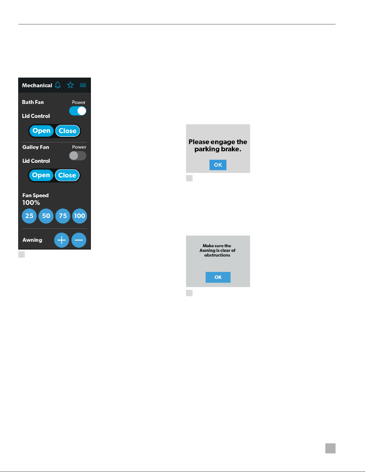
The Dometic Interact system allows you to:
•Control the climate, lighting, awnings, slide-outs,
water systems, and generators from convenient
locations in and around your vehicle.
•Monitor the status of water tank levels, LP gas levels,
and battery levels from any location.
•Predict the usage of onboard components. Predictive
usage technology provides on-screen reporting of vital
water and power resources, and determines when you
should consider refilling or recharging.
2.1 Key Features
Dometic Interact has the following features and benefits
when integrated with your RV:
• Convenient 3.5 in. (89 mm) touch-screen display
• Wireless network control and mobile application
• Single- or multiple-screen interfaces
• One-touch control for user-programmable modes,
such as Home, Away, and Sleep
• Haptic touch and sound feedback
• On-screen predictive usage
• Control and monitoring of your RV's vital and
convenience features, such as:
– Lights
– Climate
– Generator
– Inverter
– Water holding tanks
– Water pump
– Water heater
– Awning
– Alarm clock
– Coach battery
3Intended Use
Dometic Interact is intended to be used in conjunction
with the existing control and/or monitoring devices
within your RV. It creates a central hub that you can use to
efficiently control and monitor your appliances, via the
onboard touch-screen display or from your mobile
application.
The manufacturer accepts no liability for damage in the
following cases:
• Faulty assembly or connection
• Damage to the product resulting from mechanical
influences and excess voltage
• Alterations to the product without express permission
from the manufacturer
• Use for purposes other than those described in the
operating manual
Dometic Corporation reserves the right to modify
appearances and specifications without notice.
4Operation
• Avoid improper operation of the unit. Refer to the
operating manuals for the specific products that this
unit controls to understand and obey the applicable
safety precautions.
• Do not allow anyone (including children) with reduced
physical, sensory, or mental capabilities, or lack of
experience and knowledge to use this product, unless
they have been given supervision or instruction
concerning the use of this product by a person
responsible for their safety.
Dometic Interact can be operated from the onboard
touch-screen display, or via the mobile application
(available for download on most mobile devices).
!WARNING: FIRE AND/OR IMPACT HAZARD.
Failure to obey the following warnings could
result in death or serious injury:
IYou can use multiple screens for different operations
at the same time, but avoid performing a single
operation from multiple screens.

Dometic Interact Operation
5
EN
Refer to the following sections for more information about
touch-screen and mobile application navigation and use,
including information about:
• UI screens and buttons
• Control and monitoring functionality
• Prerequisites (mobile only)
4.1 Touch-Screen Navigation and
Use
This section describes how to use Dometic Interact from
the touch-screen display.
Refer to section 1.1 Mobile Application Navigation and
Use to learn how to operate the control using the mobile
application.
4.1.1 Main Navigation Screen and Icons
The Main Navigation screen is the default landing screen
that you will use to navigate through the various areas of
the control.
1 Main Navigation Screen
The Main Navigation screen provides access to the
following screens:
• Climate Screens
• Mechanical Screen
• Lights Screen
• Power Screen
• Notification Screen
• Tanks Screen
• AGS Screen
• Fuses Screen
• Settings Screen
• Room Screens
• Programs Screen
• Clock Screen
The following table describes the buttons that are used
for general navigation of the various screens and to select
settings.
IThe screens presented in this section vary according
to the available appliances and the layout of your RV. Button Description
Tap this icon to change the layout of the Main
Navigation screen to list view.
Tap this icon to change the layout of the Main
Navigation screen to grid view.
Tap this icon to close the current screen and return
to the previous screen.
Tap this icon to reach the Programs screen.
Tap this icon to reach the Notifications screen.
Tap this icon to reach the Scheduler Away
options.
Tap this icon to return to the Main Navigation
screen.
Use toggle buttons to enable or disable functions.
Use tumblers to select from a list of available
options. Tumblers can be horizontal or vertical.
Scroll to bring the desired setting to the middle
position.
Use sliders to increase or decrease the intensity of
certain settings, such as light sources. Sliders can
be horizontal or vertical. Slide the dot along the
bar to the desired intensity. The indicator shows
the intensity level as a percentage.

Operation Dometic Interact
6EN
4.1.2 Climate Screens
The Climate screens allow you to control and monitor the
climate within your RV, such as cooling, heating, and air
circulation.
2 Climate Screens
From these screens, you can manually control or monitor
the following functions:
•Current Temperatures: These indicate the current
indoor and outdoor air temperatures. The Inside and
Outside temperature values will display “- - “ if the air
temperature is outside of the sensor detection range
[< -100 or >200 °F (< -73 or >93 °C )].
•Power: The default state for this button is off. Tap the
toggle button once to turn climate control on. The
applicable climate control appliance will be activated,
depending on the set temperature and the
temperature type currently selected.
•Set Temperature: This area displays a set of numbers
ranging from 40–90 °F (4–32 °C) in ascending order.
Use the tumbler to select your desired temperature
setting.
•Climate Mode: There are four climate mode options:
Auto, Fan Only, Heat, and Cool. Tap the center bar of
the lower section indicator to view the climate mode
settings. Use the tumbler to select your desired mode.
During the compressor wait period, a moving
snowflake or heat wave icon will appear under the
outside temperature readings to show that the
compressor is waiting to heat or cool.
– Choose Auto to allow the system to select the
appropriate operating mode based on the
configured settings and actual temperature
readings.
– Choose Fan Only to turn off the AC or furnace and
use only the fan for the AC unit.
– Choose Heat to turn on the furnace or heat pump.
– Choose Cool to turn on the AC unit.
•Fan Level: Tap the right bar of the lower section
indicator to view the fan speed settings for the AC unit.
There are four fan speed options: low, medium, high,
and auto.
IThe outdoor temperature sensor may not be
available on all models.
IRefer to the Settings screen for information about
changing the Heat Mode setting to run the
furnace, the heat pump, or in automatic mode.

Dometic Interact Operation
7
EN
Use the tumbler to select your desired fan speed:
– Choose L, M, or H to set the fan to the low, medium,
or high setting.
– Choose A to set the fan to the Auto setting, where
the unit will determine the appropriate fan speed
automatically based on the set temperature and the
actual temperature readings.
4.1.3 Scheduler Screens
The Scheduler screens allow you to monitor and
automatically control the climate within your RV.
3 Scheduler Screens
Select the clock icon to activate the Climate Scheduler.
From the Scheduler screens, you can automate the
following functions:
• Scheduler: The default state for this button is off. Tap
the toggle button once to turn the Scheduler on. After
confirmation, the scheduler control will be activated
based on the set temperature and time.
4 Scheduler Confirmation Message
• Wake: The time the programmed waking temperature
will be active. Tap the display time to open the Wake -
Set Time screen and set the Wake start time. The Wake
schedule will override the manual settings until the
Scheduler is turned Off, the Sleep time is reached, or
the Away setting is activated.
• Sleep: The time the programmed sleep temperature
will be active. Tap the display time to open the Sleep -
Set Time screen and set the Sleep start time. The Sleep
schedule will override the manual settings until the
Scheduler is turned Off, the Wake time is reached, or
the Away setting is activated.
• Away: Tap the Now button once to pause the
Scheduler control temporarily. The Away temperature
will override the manual settings until the Scheduler is
turned Off, or until the Return button is selected.
• Return: Tap the Now button once to resume the
Scheduler control settings.
• Temperature: Tap the Temperature button once to
open the Temperature screen. Set the temperatures
for the Wake, Sleep, and Away environments when the
Scheduler is turned on.

Operation Dometic Interact
8EN
4.1.4 Mechanical Screen
The Mechanical screen allows you to control and monitor
your mechanical appliances, such as awnings and
ventilation fans.
5 Mechanical Screen
From this screen, you can control and monitor the
following functions:
•Power: The default state for the bath and galley fan
Power buttons is off. Tap the Power button once to turn
the fan on.
•Lid Control: The bath and galley fan lids are closed by
default. Tap the Open or Close button for the galley or
bath fan lid control to open or close the lids. A white
outline around the button indicates the status of the lid.
•Vent Fan Speed: The Fan Speed buttons control the
speed of the galley vent fans. Tap a button to choose
the desired vent fan speed from the four available
options, which represent the percentages of the
maximum fan speed: 25, 50, 75, or 100.
•Awnings: The Awning buttons allow you to extend or
retract the awning. Awnings will have no control unless
the parking brake is engaged. If you attempt to extend
or retract the awnings while the parking brake is not
engaged, an alert appears.
6 Parking Brake Alert
The Awning buttons function as follows:
– Tap the plus button (+) to extend the awning or the
minus button (–) to retract the awning, and a pop-up
message appears (assuming the parking brake is
engaged).
7 Awning Clear Message
– After you have verified that the awning is clear of
obstructions, tap the OK button. The awning is now
ready to extend or retract.
IThe lid must be open before the fan motor turns
on. If the lid is closed when you attempt to turn the
fan motor on, the lid will open automatically.
The fan must be off when the lid is closed. If the fan
is on when you close the lid, the fan will turn off
automatically.

Dometic Interact Operation
9
EN
4.1.5 Lights Screen
The Lights screen allows you to control and monitor the
various lighting sources throughout your RV, such as
accent, galley, utility lighting, and the other lights.
8 Lights Screen
From these screens, you can control and monitor the
following functions:
•Power Buttons: The power buttons are used to turn a
particular light on and off. Tap the toggle or on/off
buttons as desired to turn the lights on or off.
•Dimmer/Slider: The light source intensity is
indicated when the power to the light is activated. Tap
the intensity indicator to open the vertical slider screen,
where you can adjust the light source intensity.
4.1.6 Power Screen
The Power screen allows you to monitor and control the
available power sources for your RV, such as the battery,
inverter, and generator.
9 Power Screen
IThe Shower, Assist Handle, and Utility Center
lights do not dim.

Operation Dometic Interact
10 EN
From the Power screen, you can control and monitor the
following functions:
•Inverter Power: Use the toggle button to turn the
inverter ON or OFF. The Operating Mode indicator
displays the operating mode of the inverter:
– Pass Thru indicates the inverter is bypassed, when
the shore power is hooked up.
– Inverting indicates the inverter is Enabled.
– Waiting to Invert indicates the inverter is Enabled but
is not yet actually producing AC power.
– Load Sensing indicates the inverter is waiting for the
load.
The following modes display on the inverter LCD
screen. Refer to the Xantrex Inverter Manual for more
information.
– Battery mode indicates that the inverter is running
and supplying AC power to the loads from battery.
– Grid mode indicates that the inverter is charging the
battery with AC voltage from shore power, but it is
bypassing the inverter supply of AC power to the
loads directly from the shore power.
– Off appears when the inverter is either off, or it is in
an error, fault, or warning state.
•Battery: These indicators provide voltage readings for
the chassis (engine) and house (coach) batteries,
respectively.
•Load Wattage (Inverter Load Wattage): This
indicator displays the power consumed by the load
from the inverter when in battery mode.
•Charger Stage: This indicator shows the charger
status of the onboard charger, as described in the
following table:
•Charger Current: This indicator shows the current
that the charger is drawing from shore power.
•AC Input Current: This indicator shows the input
current being drawn from shore power.
•AC Load Current: This indicator shows the current
that the loads are drawing directly from shore power,
bypassing the inverter.
•Generator: These options control both input and
output, so you can monitor and control the onboard
generator:
– The hours indicator shows the number of hours that
the generator has run.
IIf the inverter is in an error, fault, or warning state,
the error code will be indicated on the inverter
LCD screen in the inverter compartment.
Number Status Description
0 Disabled The charger is disabled.
1 Not
Charging
The charger is enabled, but it is not
charging (typically due to a lack of
AC power).
2 Bulk The charger is in the initial stage of
the three-stage charging cycle.
3 Absorption The charger is in the second stage of
the three-stage charging cycle.
4 Over
Charge
The charger is over-charging the
batteries (this status is rare).
5 Equalize The charger is equalizing the
batteries.
6 Float The charger is in the third stage of
the three-stage charging cycle.
7 Constant
Voltage
The charger is providing constant
voltage charging (typically used
during single-stage charging cycles).

Dometic Interact Operation
11
EN
– The status indicator shows the state of the
generator, as described in the following table:
– The START and STOP buttons control the output of
the generator. Tap the START button to start the
generator. The status changes to Cranking, and then
to Running. A pop-up message should also appear.
10 Ventilation Alert
•AGS: The Automatic Generator Start (AGS) indicator
shows the status of the auto generator: ON, OFF, or
disabled due to Quiet Time or External Activity. There
is also a CLEAR AGS button; when external activity is
detected, tap this button to override the external
activity demand and turn the AGS on.
External activity is a mechanism used to disable the
AGS if the generator is manually stopped or started.
This is a safety feature implemented so that if you
manually stop the generator, the AGS system does not
attempt to start it up again.
The Power screen also has a settings icon that you can tap
to reach the Advanced Inverter Settings screen.
11 Advanced Inverter Settings Screens
Number Status Description
0 Stopped The generator is stopped.
1 Pre-Heat The generator is
preheating. This is done
prior to the cranking cycle.
2 Cranking The generator is starting.
3 Running The generator is running.
4 Priming The generator is
advancing fuel.
5 Fault There is a fault.
6 Engine Run Only The generator is running,
but not producing AC
power.
7 Test Mode This status is unused.
8 Voltage-Adjust-Mode This status is unused.
9 Fault-Bypass-Mode This status is unused.
10 Configuration-Mode This status is unused.
IFor a complete list of generator statuses, refer to
the RV-C Specifications PDF.

Operation Dometic Interact
12 EN
12 Advanced Inverter Settings Screens (continued)
The advanced inverter settings are for technicians only,
and a pop-up message appears when you tap the
advanced inverter icon.
13 Advanced Inverter Settings Notification
Tap the CANCEL button to return to the Power screen, or
tap the GO ANYWAY button to proceed to the
Advanced Inverter screen.
From the Advanced Inverter Settings screen, technicians
can control or monitor the following functions by tapping
the expand/contract arrows, toggle buttons, EDIT, and
OK buttons as applicable:
•Inverter Ignition Control: This button adjusts the
ignition control setting.The default setting is Off. Tap
the tumbler to select Automatic, Lockout, or Off.
•LBCO Voltage: This button adjusts the voltage
setting.The default setting is 10.5 V. Tap the Edit
button to adjust the value in 0.1 V increments. The
inverter is able to recover automatically at LBCO
voltage + 0.2 V.
•LBCO Shutdown Delay Timer: This button adjusts
the shutdown timer.The default setting is 300 sec. Tap
the Edit button to adjust the value in 10-sec increments.
•LBCO Recovery Voltage: This button adjusts the
recovery voltage setting.The default setting is 13.1 V.
Tap the Edit button to adjust the value by 0.1 V
increments. Selecting a value higher than the battery’s
actual fully-charged voltage level will not activate the
auto-recovery feature. Manually reset the inverter
charger when the low-battery cut-off event occurs.
•Power Save Time: This button sets the countdown
timer to shut down the inverter operation automatically
to reduce the battery discharge and to preserve the
battery life. The countdown timer range is between 1
and 25 hours. The default setting is 25 hours. During a
continuous inverter operation, the countdown initiates
when the power from the AC load drops to less than
approximately 50 W and remains below this level.
After reaching the end of the countdown timer, the
inverter charger automatically shuts down.
•Power Save Mode: This button enables the power
save mode setting. The default setting is Off. Tap the
toggle button On to allow the inverter charger to go to
load sense mode automatically by sending short
pulses to further reduce the battery discharge. Power
save mode ends when a load greater than 25 W is
connected.
•Output Frequency: This button adjusts the output
frequency setting. The default setting is 60 Hz.
Depending on the country or location, tap the toggle
button to change the value to 50 Hz and then turn the
unit Off and On again for the change to take effect.
•Output Voltage: This button adjusts the output
voltage setting. The default setting is 120 V. Tap the
tumbler to select the value.
•Inverter Output Power Limit: This button adjusts
the wattage limit for outgoing power. The default
setting is 2 kW. Tap the Edit button to adjust the value
in 100 W increments. Use with the Inverter Output
Power Limit Timer if pairing with a lithium ion battery.
IThere are some configurable settings available from
the inverter LCD display.

Dometic Interact Operation
13
EN
•Inverter Output Power Limit Timer: This button
adjusts the power limit timer.The default setting is 300
sec. Tap the Edit button to adjust the value in
10-sec increments. Use with the Inverter Output Power
Limit if pairing with a lithium ion battery. The timer is
automatically disabled if the maximum limit is selected.
•Transfer Mode: This button adjusts the line to battery
transfer time setting. The default setting is Appliance
(APL) at 20 ms. Tap the toggle button to change to the
uniterruptible power supply (UPS) setting of 10 ms.
•Utility AC Under Voltage Level: This button sets the
minimum acceptable AC under voltage level from the
shore power if an under-voltage outlet exists. The
default setting is 90 V. Tap the Edit button to change
the minimum acceptable AC under voltage level.
•Battery Temperature: This button adjusts the
battery temperature setting. The default setting is Hot.
Tap the Edit button to select from Cold, Warm, or Hot.
•Custom Absorption Voltage: This button adjusts
the absorption voltage for the custom battery type. The
default setting is 14.6 V. Tap the Edit button to adjust
the value in 0.1 V increments.
•Custom Float Voltage: This button adjusts the float
voltage level for the custom battery type. The default
setting is 13.5 V. Tap the Edit button to adjust the value
in 0.1 V increments.
•Inverter Shutdown Recovery: This button sets the
restart method if the inverter shuts down due to an over
temperature, overload, or short circuit condition. The
default setting is a manual restart. Changing the setting
to auto-restart will cause the inverter to attempt to
restart automatically up to three times if a shut down
occurs. if the inverter is shut down for the fourth time,
additional restarts must be attempted manually, as
there may be a safety concern related to the shut
down. Tap the toggle button to allow a manual restart
via the display panel.
•Audible Alarm: This button toggles an alarm on or off
that beeps every 5 seconds. The default setting is On.
•Battery Type: This button sets the battery type. The
default setting is Flooded (FLd). Tap the Edit button to
change the battery type installed.
•Max Charger Current: This button adjusts the
maximum charging current allowed to charge the
batteries from the inverter. The default setting is 80 A.
Tap the Edit button to adjust the value in 5 A
increments.
•Equalize Charging: This button allows one hour of
equalized charging. The default setting is Off. Tap the
Start button to begin charging.
•AC Input Breaker - Load Share: This button adjusts
the load share setting to prioritize the AC load. The
charge current is reduced to maintain the total input
current at less than the load share setting. The default
setting is 30 A. Tap the Edit button to select the load
share setting.
Complete the following steps to change the default value
to a different value:
1. Tap the expand/contract button for the feature
setting that you want to update.
2. Based on the available options for the selected
feature, complete one of the following actions:
– Tap an option from the list.
– Tap the toggle button to activate/deactivate the
feature.
– Tap the EDIT button to view the available settings for
the value.
IDo not connect to the motor loads when the setting
is in UPS mode.
IChanging the battery temperature setting from Cold
to Warm will increase the charger voltage by 0.4 V.
Changing the battery temperature setting from Cold
to Hot will increase charger voltage by 0.8 V.
IAvailable only for a custom battery type.
IAvailable only for a Flooded battery type.

Operation Dometic Interact
14 EN
3. If the EDIT button is selected:
a. Change the value as desired.
b. Tap the OK button to confirm the change and
return to the Advanced Inverter Settings screen.
4. Repeat the previous steps to set the other feature
settings as applicable.
5. After all updates are complete, tap the exit (x) icon to
leave the feature settings mode and return to the
Power screen.
4.1.7 AGS Screen
The AGS (Auto-Gen Start) screen allows you to monitor
and control the automatic generator settings, such as the
scheduled on/off times, scheduled run times, and
voltages.
14 AGS Screen

Dometic Interact Operation
15
EN
From this screen, you can control and monitor the
following functions:
•Auto Charger: Use this toggle button to enable or
disable the auto charger. The auto charger is disabled
by default. When you enable the auto charger, a pop-
up message appears.
15 Ventilation Alert
The AGS becomes disabled if the ignition is turned on.
If you attempt to enable the auto charger while the
ignition is on, a pop-up message appears.
16 Ignition Alert
The following auto charger settings are available:
–Quiet Time: Use the available tumblers (hour and
minute) to set the desired quiet time start and end
times. The generator is turned off automatically
during the specified quiet time.
–Start Voltage: Use the tumbler to set your desired
voltage setting (10 V–12.9 V). The default setting is
10.5 V. The Start Voltage tumbler controls the
threshold voltage under which the AGS must
turn on.
–Time Under: Use the tumbler to set your desired
timer setting (0–10 min). The Time Under tumbler
specifies the timer delay before the AGS starts,
when the system drops below the set threshold
voltage.
•Climate AGS Mode (AGS Climate): These options
enable the climate controls to run the air conditioner
and heat pump off the generator when no shore power
is available.
•Generator Exerciser: Use the toggle button to
enable or disable the generator exerciser.
When you enable this setting, the Ventilation Alert
pop-up message appears. The alert message does not
appear when the generator activates based on the set
schedule. The generator runs as scheduled if the
ignition is turned off. If the ignition is turned on during
a particular day that the generator is scheduled to run,
it would skip running the generator that day unless the
ignition is turned off.
The available generator exerciser settings are:
–Days: Tap the desired days to specify the days on
which the generator exerciser should run.
–Run Time: This tumbler controls the duration for the
generator exerciser. Use the tumbler to set your
desired time setting (0–1250 min).
–Start Time: These tumblers control the time at
which the generator exerciser should start. Use the
available tumblers (hour and minute) to set your
desired time settings.
4.1.8 Tanks Screen
The Tanks screen allows you to monitor and control the
holding tanks, such as the fresh, gray, and black water
tanks.
17 Tanks Screen

Operation Dometic Interact
16 EN
From this screen, you can monitor and control the
following functions:
•Indicator Bars: The horizontal bars indicate the fluid
levels for the various tanks (percent full), which are
monitored continuously by the sensors attached to the
outside of the tanks. These indicators are for
monitoring purposes only and do not have any control
functions
•Predictive Monitoring: Touch anywhere on the
horizontal tank indicator bars to display a predictive
monitor for that tank.
18 Predictive Monitoring Screen
The information includes the average liquid usage, the
average drainage per day, and the empty-to-full ratio
for fresh and gray/black tanks respectively.
•Water Pump: Use this toggle button to turn the water
pump on or off. The water pump is deactivated by
default.
•Truma Water Heater: While a Truma Water Heater
comes with its own control panel, you can also operate
three settings from the Dometic Interact.
19 Truma Water Heater Controls Screen
The Dometic Interact shows a ‘Decalcification’ status
when you set the water heater to the Clean mode from
the Truma control panel. Due to lime deposits from
hard water, the appliance should be decalcified
regularly. The decalcification process takes
approximately three hours and cannot be interrupted
after it is started. Refer to the Truma manual for the
frequency of decalcification and the safety precautions
during this operation):
–Off: Tap to turn the water heater OFF if it is currently
ON.
–ECO: Tap to maintain the water in the tank at an
above-freezing temperature of 41 °F (5 °C).
–Comfort: Tap to maintains the water in the tank at a
standard temperature of 102 °F (39 °C).
IIf the Truma system produces an error or
communication, it will show on the Dometic
Interact Notification screen.
- Truma Water Heater Error
- LIN Bus Communication Error
If these errors occur, try to operate the water
heater from the Truma Control Panel. If the error is
not resolved, contact Truma Support.
IAn additional Anti-Freeze setting is available on
the Truma Water Heater control panel if an electric
anti-freeze kit is installed separately.

Dometic Interact Operation
17
EN
4.1.9 Settings Screen
The Settings screen allows you to control and configure
the various aspects of the system and control, such as
screen brightness and audio levels.
20 Settings Screen
Refer to the sections that follow for more information
about the Settings screen.
4.1.9.1 General Info Section
Use this section of the Settings screen to find general
legal information and to learn about the system:
• Tap Legal to open the Legal window.
21 Legal Window
• Tap About to open the About window.
22 About Window
4.1.9.2 Config Mobile App Section
Use this section of the Settings screen to configure the
mobile application connection settings from the touch-
screen display:

Operation Dometic Interact
18 EN
Tap the GET button to open a window that contains a
scannable QR code, which leads to the mobile
application download from the App Store or Google Play
Store.
23 QR Code Window - iOS
24 QR Code Window - Android
•SSID: This text-only indicator displays the name of the
network to which the multiplex system is connected.
•IP Address: This numeric indicator displays the IP
address where the mobile app should be directed. For
example, the indicator will display IP address
192.168.8.1 if the Wi-Fi device is in Access Point mode,
and display a different IP addess if it is in Infrastructure
mode.
4.1.9.3 Satellite Dish Option
Use the Satellite Dish toggle button to turn the satellite
dish on or off.
4.1.9.4 Default Room Section
Use this section of the Settings screen to set the default
room that appears on the Main Navigation screen:
1. Tap the EDIT button to open the Default Room screen.
25 Default Room Window
2. Choose from the list of available rooms (Bedroom,
Entry, or Bathroom).
3. Tap the OK button to save your selection and return
to the Settings screen.
4.1.9.5 Standby Screen Section
Use this section of the Settings screen to set the screen
that should appear when you are outside of the sensing
range of the proximity sensor:
1. Tap the EDIT button to open the Standby Screen
window.
26 Standby Screen Window
IIf the Dometic Multiplex System is connected to the
Wingard WiFi and you change the password for
Winegard, the Dometic Multiplex system will lose its
WiFi connection with Winegard. Reconnect the
LR-125 WiFi module of the Dometic Multiplex
System to the Winegard WiFi.
IThis option will display on the Settings screen, even
if a satellite dish is not installed.

Dometic Interact Operation
19
EN
2. Choose from the list of available display options:
–Dimmed: The screen dims to 30% brightness until
the proximity sensor senses movement.
–Clock: The screen displays the Clock screen until
the proximity sensor senses movement. Refer to the
Clock Screen section for more information.
–Sleep: The screen goes black until the proximity
sensor senses movement.
3. Tap the OK button to save your selection and return
to the Settings screen.
4.1.9.6 Set Date & Time Section
Use this section of the Settings screen to set the current
date and time:
1. Tap Date to open the Date window.
27 Date Window
2. Use the day, month, and year tumblers to set the
current date.
3. Tap the SAVE button to save your selections and
return to the Settings screen.
4. Tap Time to open the Time window.
28 Time Window
5. Use the AM/PM radio buttons and the hour and
minute tumblers to set the current time.
6. Tap the SAVE button to save your selections and
return to the Settings screen.
7. Tap Time Zone to open the Time Zone window.
29 Time Zone Window
8. Use the tumbler to select your time zone.
9. Tap the SAVE button to save your changes and return
to the Settings screen.
IWhen you move into the sensing range of the
proximity sensor, the display will show the start
page that you selected.
IThe AM/PM radio buttons will not appear if the
time format is set to 24-hour.
ISetting the Date / Time on one Dometic Interact
Touch panel will update the time and date on all
the other panels.

Operation Dometic Interact
20 EN
4.1.9.7 Heat Mode Section
Use this section of the Settings screen to set the method
of heating:
1. Tap the EDIT button to open the Heat Mode window.
30 Heat Mode Window
2. Choose from the list of available heat modes:
–Heat Pump: Only the heat pump runs when the
coach requires heating.
–Auto: The furnace and/or heat pump will run when
the coach requires heating. The furnace will only
turn on if the temperature drops below the set point.
The furnace is used as a secondary boost for the heat
pump if the temperature gets cold enough. Auto is
the default setting for Heat mode. When in this
mode and:
– If the outside temperature is above 40 °F (4 °C),
and the inside temperature is less than the Heat
Set Point, then the heat pump will be on.
– If the difference between the inside temperature
and the Heat Set Point is more than 5 °F (3 °C),
then the furnace will be on.
– If the outside temperature is below 40 °F (4 °C),
then the furnace will be on even when the differ-
ence between the inside temperature and the
Heat Set Point is less than 5 °F (3 °C).
–Furnace: Only the furnace runs when the coach
requires heating.
3. Tap the OK button to save your selection and return
to the Settings screen.
4.1.9.8 Temperature System
Use the Temperature System toggle button to set your
desired temperature readings (in degrees Centigrade or
Fahrenheit).
The side of the toggle button that holds the dot indicates
the current selection.
4.1.9.9 Brightness Mode
Use the Brightness Mode toggle button to choose
between Auto (A) or Manual (M) adjustment modes:
• When the auto option is selected, the brightness is
adjusted according to the ambient light sensor values.
• When the manual option is selected, you can adjust the
screen brightness manually.
4.1.9.10 Screen Brightness
Use the Screen Brightness slider to manually set your
desired screen brightness level (shown as a percentage
of full intensity).
In order to set the screen brightness, the manual
brightness mode must be selected.
4.1.9.11 Audio Level
Use the Audio Level slider to set your desired audio level
intensity for the control (shown as a percentage of full
intensity).
4.1.9.12 Time Format
Use the Time Format toggle button to set your desired
time format (in 12-hour or 24-hour formats).
The side of the toggle button that holds the dot indicates
the current selection.
4.1.9.13 Inverter Sleep Enable
Use the Inverter Sleep on/off button to make the system
turn the inverter off at startup.
4.1.10 Programs Screen
The Programs screen allows you to control the
predefined scenes with one touch of a button.
Other manuals for PCD5501
1
Table of contents
Languages:
Other Dometic Motorhome manuals