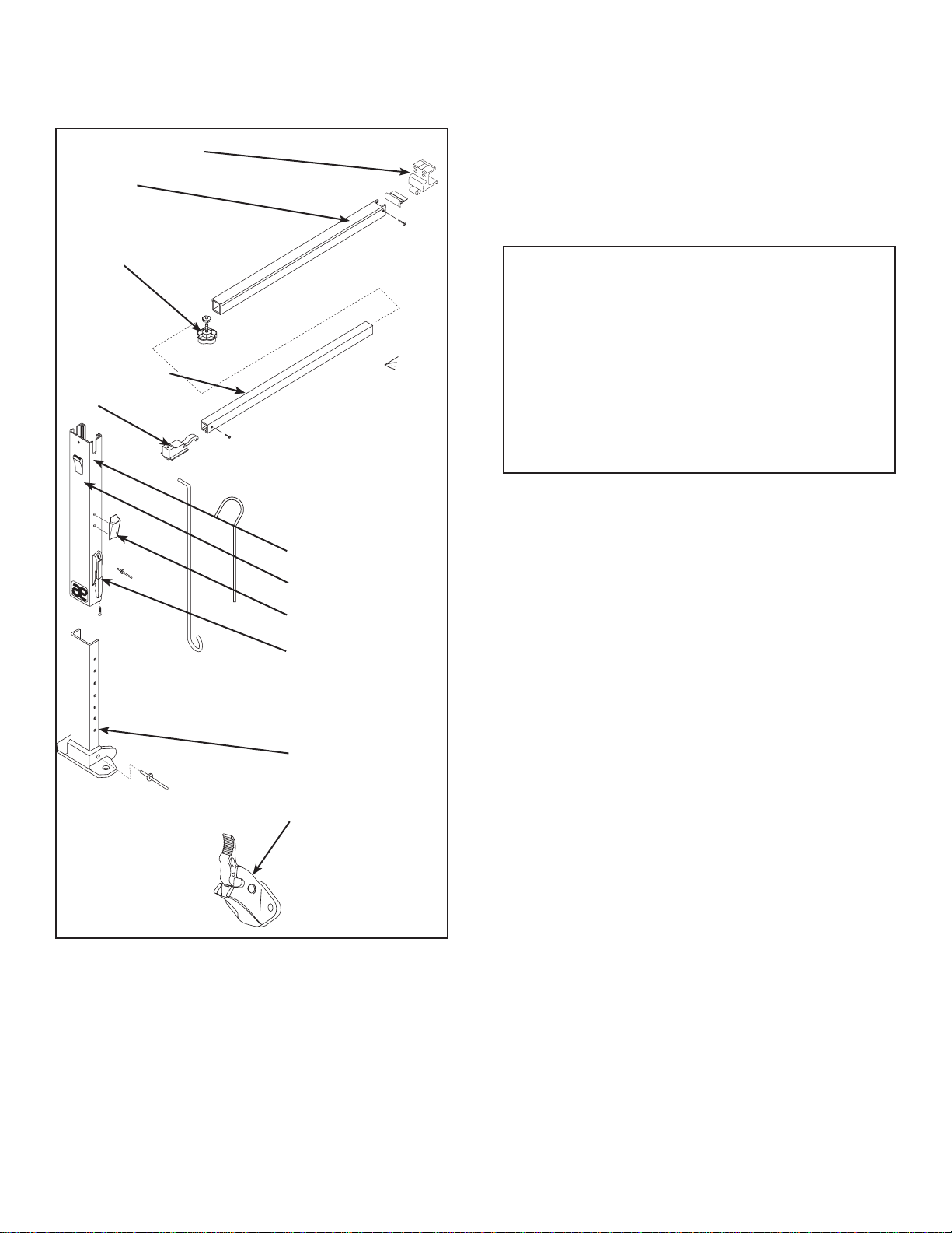
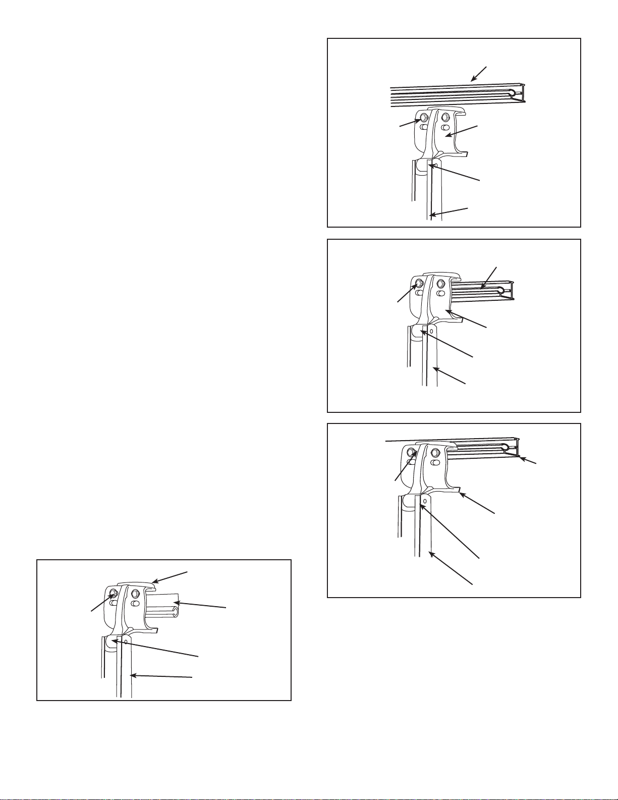
10
Molding
Standoff Kit 3104781.XXX
Bottom Wall Bracket
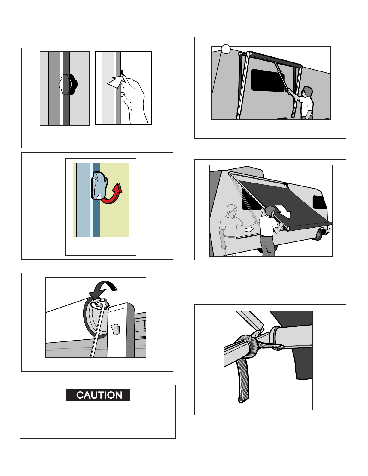
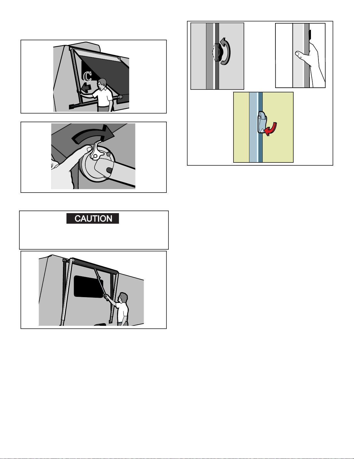
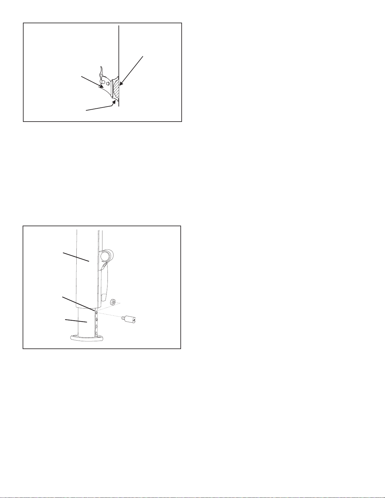
2.7 Stop Plug
The stop plug is a mechanical stop that supports the main
arm when opening and closing the awning. It controls the
clearance between the top casting of the torsion and the
extension of the top mounting bracket. This clearance
should be 1/4 inch to 1 inch. To adjust the clearance, raise
or lower the stop plug as needed. On the 9000 Series
awning the clearance should be kept to a minimum for
best operation.
2.8 RAFTERS
The rafters telescope from the top mounting brackets to
the main support arms to provide tension on the fabric in
the full open position. If the rafters are bent or twisted,
this will hinder the operation of the awning. Open the aw-
ning and remove the secondary rafter from the main sup-
port arm. Sight down the main and secondary rafters and
check for any bends, twists or deection. If one or the
other rafter is not true it should be replaced.
Note: A bent rafter arm is not a warranty item. If the arm
was straight at delivery and unit is bent now, something
has bent the arm as improper operation or an act of na-
ture.
Fabric Roller Tube Assembly (FRTA)
The fabric roller tube assembly consist of Fabric, Alumi-
num Guard (858 & 9000 only), Roller Tube and Torsions.
Each component can be diagnosed, then repaired or re-
placed. The 9000 fabric is woven acrylic, not canvas. In
addition to its beauty and soft translucence, woven acrylic
fabric offers the advantages of strength and breath abil-
ity. It is water repellent but because it is a woven cloth,
it is not water proof. To keep your acrylic awning clean,
simply hose it off occasionally and let it dry. Do Not Scrub.
Avoid touching the underside of the 9000 canopy when it
is wet. To do so will break the surface tension of the wa-
ter and encourage seepage through the fabric. Because
the acrylic is woven not a solid vinyl, shifting may occur
if the awning and pull strap are not centrally aligned with
the fabric roller tube while the awning is being rolled up.
If necessary, roll the awning out and adjust the alignment
as you close the awning. The 8300 and 8500 is a vinyl,
nylon reenforced fabric. Abrasion and harsh weather are
vinyl’s worst enemies. To avoid abrasion, you will need to
keep your awning fabric clean. Use a mixture of 1/4 cup
dish soap, 1/4 cup bleach and ve gallons of fresh water.
Soap the open awning with this mixture, then roll it up and
let stand for ve minutes. Rolling up of the awning will ap-
ply the mixture to the underside of the fabric. Unroll the
awning and hose off the top and bottom with clean water.
Repeat if necessary and allow to completely dry.
Section 3
3.1 Fabric
For the awning to operate properly the fabric must be
positioned properly in the awning rail and on the roller
tube. Open the awning and check the position of the fabric
between the top mounting brackets. If the fabric is not
centered,removethetekscrews,centerit,andreplacethe
screws. Once the fabric at the rail is properly positioned,
next check the position of the fabric on the roller tube.
The clearance from the end cap of the torsion assembly
to the edge of the fabric must be the same on each end.
If it is not, adjust the fabric on the tube as necessary. On
the Elite 9000 and 9500 awning the fabric is held in place
to the weatherguard with set screws. Check the position
of the fabric at each end of the weatherguard. If the fabric
has shifted, remove set screws, center the fabric and re-
set. An awning that the fabric has shifted will open and
close hard.
3.1.1 Position
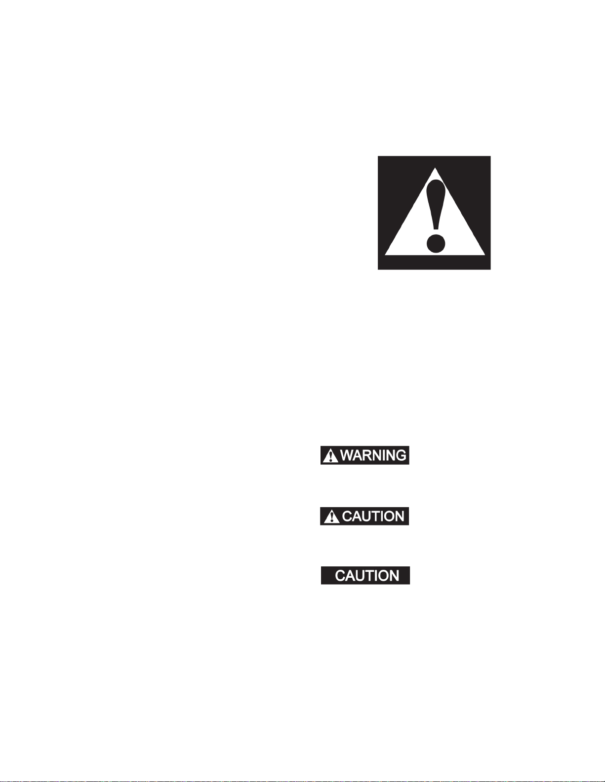
3.1.2 TEK Screws
The Tek screws are the two screws installed through the
awning rail of the coach. They keep the fabric from shift-
ing in the awning rail. On vinyl and acrylic awnings they
keep the poly rope in the fabric from shrinking with age.
If one Tek screw is missing, the fabric will pull toward the
remaining Tek screw causing the fabric to wrinkle. With
the awning open, remove the tek screws and pull outward
on the fabric, stretch it, and re secure the screw. Do this
on both sides to assist with the wrinkles at the weather
guard and fabric. If wrinkles are still present, repeat the
above stretching procedure. This may have to be done 4
or 5 times before all wrinkles disappear.
5/16" - 18
Lock Nut
5/16" - 18 x 1"
Shoulder Bolt
Inner Arm
Main Arm
3/8” Dia. Hole
Closest To
Main Arm
Inner Arm
Main Arm
3/8" Dia. Hole
Closest To
Main Arm