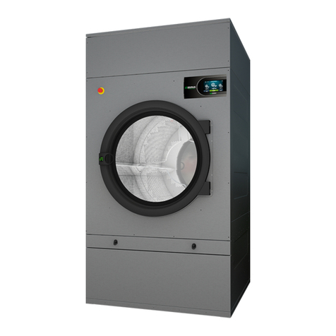
Domus UDTT-2-25 Operating instructions

12232540
MANUAL DE USO Y MANTENIMIENTO
GEBRAUCHS UND WARTUNGSANLEITUNG
MANUALE D’ISTRUZIONI E MANTENIMENTO
MANUAL DE OPERAÇÃO E MANUTENÇÃO
SP-08 / SP-10
12283320 19/03/2021
USER AND MAINTENANCE
DOMUS STACK TUMBLE DRYERS
NOTICE D’EMPLOI ET MAINTENANCE
DOMUS SÈCHE-LINGE
UDTT -2-25 / -2-35
UDTM -2-25 / -2-35
UDLM -2-25 / -2-35

WARNING:
FIRE OR EXPLOSION HAZARD
Failure to follow safety warnings exactly could result in
serious injury, death or property damage.
-Do not store or use gasoline or other flammable vapors
and liquids in the vicinity of this or any other appliance.
-WHAT TO DO IF YOU SMELL GAS
•Do not try to light any appliance.
•Do not touch any electrical switch; do not use any
phone in yor building.
•Clear the room, building or area of all occupants.
•Immediately call your gas supplier from a neighbor’s
phone. Follow the gas supplier’s instructions.
•If you cannot reach your gas supplier, call the fire
department.
-Installation and service must be performed by a qualified
installer, service agency or the gas supplier.
2

ATTENTION :
RISQUE D'INCENDIE OU D'EXPLOSION
Le non-respect des avertissements de sécurité peut
entraîner des blessures graves, la mort ou des dommages
matériels.
-Ne pas entreposer ni utiliser d'essence ou d'autres
vapeurs et liquides inflammables à proximité de cet
appareil ou de tout autre
-QUE FAIRE SI VOUS SENTEZ UNE ODEUR DE GAZ
•Ne branchez pas d’appareils
•Ne touchez à aucun interrupteur électrique; n'utilisez
aucun téléphone dans votre immeuble.
•Evacuez la pièce, immeuble ou zone de tous les
occupants
•Appelez immédiatement la compagnie de gaz d’un
téléphone extérieur/voisin. Suivez les indications et
instructions de la compagnie de gaz
•Si vous ne pouvez pas joindre la compagnie de gaz,
téléphoner aux pompiers.
-L’installation et la maintenance doivent être faites par une
personne, agence ou compagnie de gaz qualifiée.
3

Post the following note in a prominent place.
Affichez la note suivante dans un endroit bien en vue,
Post prominently the instructions to follow if you smell gas. The information to be
published will be obtained in consultation with the local gas supplier.
Affichez bien en vue les instructions à suivre si vous sentez une odeur de gaz.
Les informations à publier seront obtenues en concertation avec le fournisseur de
gaz local.
FOR YOUR SAFETY
Do not store or use gasoline or other
flammable vapors and liquids in the
vicinity of this or any other appliance.
POUR VOTRE SÉCURITÉ
Ne pas entreposer ni utiliser
d'essence ou d'autres vapeurs et
liquides inflammables à proximité de
cet appareil ou de tout autre.
4

–CONTENTS (EN) –INDEX (FR)–
1. SAFETY INFORMATION ................................................................................. 8
2. GENERAL SPECIFICATIONS ......................................................................... 9
2.1. Overview and dimensions...........................................................................................................................10
3. INSTALLATION ............................................................................................. 11
3.1. Tools...........................................................................................................................................................11
3.2. Location......................................................................................................................................................11
3.2.1. Transport and storage. ........................................................................................................................11
3.2.2. Location..............................................................................................................................................12
3.2.3. Levelling............................................................................................................................................13
3.3. Vapour extraction.......................................................................................................................................13
3.3.1. Entrance of fresh air............................................................................................................................13
3.3.2. Output pipe .........................................................................................................................................14
3.4. Electrical connection..................................................................................................................................16
3.5. Connection to gas (only gas models)..........................................................................................................17
3.6. Injector replacement / Conversion kits.......................................................................................................19
4. OPERATION OF ELECTRONIC CONTROL ................................................. 23
4.1. Principle and description of the control of the machine ............................................................................23
4.2. ELECTRONIC CONTROL:........................................................................................................................23
4.2.1. Information displayed with the indicator lights..................................................................................24
4.2.2. Functions associated to the buttons ....................................................................................................25
4.2.3. Self-service mode ...............................................................................................................................25
4.2.4. Self-recognition mode ........................................................................................................................26
4.2.5. Other functions ...................................................................................................................................27
4.3. How to run a drying cycle ..........................................................................................................................27
4.3.1. How to finish drying...........................................................................................................................28
4.4. ALARMS AND WARNINGS........................................................................................................................28
5. PRINCIPLE AND DESCRIPTION OF THE TOUCH CONTROL .................... 29
6. INTERFACE .................................................................................................. 29
6.1. OPL: SCREEN OFF...................................................................................................................................30
6.2. OPL: MAIN SCREEN.................................................................................................................................30
6.3. OPL: RUN SCREEN...................................................................................................................................31
6.4. SELF-SERVICE: SELECTION SCREEN 1 - BUTTONS: ..........................................................................32
6.5. SELF-SERVICE: SELECTION SCREEN 2 - PAYMENT...........................................................................33
6.6. SELF-SERVICE: RUN SCREEN................................................................................................................34
7. CONFIGURATION ......................................................................................... 34
7.1. Programme management............................................................................................................................35
7.2. Configure system ........................................................................................................................................36
5

8.1. How to finish drying...............................................................................................................................39
9. ALARMS AND WARNINGS ........................................................................... 40
10. MAINTENANCE ............................................................................................ 41
10.1. Fluff filter....................................................................................................................................................42
10.2. Heating battery...........................................................................................................................................42
10.3. Air extractor ...............................................................................................................................................43
10.3.1. Fan blades:..........................................................................................................................................43
10.3.2. Technical service................................................................................................................................43
10.3.3. Non-return valve:................................................................................................................................43
11. TROUBLESHOOTING ................................................................................... 44
11.1. Problem-Cause-Solution Table ..................................................................................................................44
12. INDICATIONS FOR REMOVING AND GETTING RID OF THE MACHINE ... 44
1. INFORMATIONS RELATIVES À LA SÉCURITÉ ........................................... 45
2. CARACTÉRISTIQUES GÉNÉRALES ............................................................ 46
2.1. Vue d'ensemble et dimensions ....................................................................................................................47
3. INSTALLATION ............................................................................................. 48
3.1. Outils ..........................................................................................................................................................48
3.2. Mise en place..............................................................................................................................................48
3.2.1. Transport et réservoir..........................................................................................................................48
3.2.2. Situation..............................................................................................................................................49
3.2.3. Mise à niveau......................................................................................................................................50
3.3. Extraction d'air...........................................................................................................................................50
3.3.1. Entrée d'air frais..................................................................................................................................50
3.3.2. Tuyauterie de sortie ............................................................................................................................51
3.4. Connexion électrique..................................................................................................................................53
3.5. Connexion à gaz (uniquement les modèles à gaz)......................................................................................54
3.6. Remplacement des injecteurs / Kits de conversion.....................................................................................56
6
–INDEX (FR)–
8. HOW TO RUN A DRYING CYCLE ................................................................ 38

6. INTERFACE .................................................................................................. 66
6.1. OPL : ÉCRAN OFF....................................................................................................................................67
6.2. OPL : ÉCRAN PRINCIPAL........................................................................................................................67
6.3. OPL : ÉCRAN D'EXÉCUTION..................................................................................................................68
6.4. LIBRE-SERVICE : ÉCRAN DE SÉLECTION 1 - BOUTONS....................................................................69
6.5. LIBRE-SERVICE : ÉCRAN DE SÉLECTION 2 - PAIEMENT...................................................................70
6.6. LIBRE-SERVICE : ÉCRAN D'EXÉCUTION..............................................................................................71
7. CONFIGURATION ......................................................................................... 71
7.1. Gestion de programmes..............................................................................................................................72
7.2. Configurer le système.................................................................................................................................73
8. COMMENT RÉALISER UN SÉCHAGE ......................................................... 75
8.1. Comment terminer le séchage ................................................................................................................76
9. ALARMES ET AVERTISSEMENTS ............................................................... 77
10. ENTRETIEN .................................................................................................. 78
10.1. Filtre à bourre............................................................................................................................................79
10.2. Batterie chauffante .....................................................................................................................................79
10.3. Extracteur d'air...........................................................................................................................................80
10.3.1. Pales de la turbine:..............................................................................................................................80
10.3.2. Service technique................................................................................................................................80
10.3.3. Clapet antiretour:................................................................................................................................80
11. PROBLÈMES ET SOLUTIONS ..................................................................... 81
11.1. Tableau de Problème-Cause-Solution........................................................................................................81
12. INDICATIONS POUR LE RETRAIT ET L'ÉLIMINATION DE LA MACHINE. .. 81
7
4. FONCTIONNEMENT DU CONTRÔLE ÉLECTRONIQUE ............................. 60
4.1. Principe et description du contrôle de la machine.....................................................................................60
4.2. CONTRÔLE ÉLECTRONIQUE :...............................................................................................................60
4.2.1. Informations visualisées à l'aide les indicateurs lumineux.................................................................61
4.2.2. Fonctions associées aux touches.........................................................................................................62
4.2.3. Mode libre-service..............................................................................................................................62
4.2.4. Mode autoreconnaissance...................................................................................................................63
4.2.5. Autres fonctionnalités.........................................................................................................................64
4.3. Comment réaliser un séchage.....................................................................................................................64
4.3.1. Comment terminer le séchage ............................................................................................................65
4.4. ALARMES ET AVERTISSEMENTS............................................................................................................65
5. PRINCIPE ET DESCRIPTION DU COMMANDE TOUCH ............................. 66

1. SAFETY INFORMATION
•Read this manual before using or installing the dryer.
•Keep this manual in a safe place for use in subsequent configurations,
•This manual must be handed over with the machine if it is sold to somebody else.
•ONLY use the machine for professional drying of textile fibres after washing in water.
•Do not leave petrol or other inflammable liquids or gases near to the dryer.
•Do not dry products that have been treated or that give off inflammable vapours or elements.
•Do not dry garments containing foam or latex, materials with a rubber texture or pillows filled with foam
rubber.
•Always bear in mind the instructions described on the labels of the materials to be dried.
•Do not leave the dryer operating unattended.
•Do not insert hands in the dryer while the drum is still rotating. The dryer should not operate when the
door is open.
•Do not touch the safety devices of the dryer.
•Do not allow children to play in or on the machine. They must be kept away from the machine,
especially if it is operating.
•Cleaning the fluff filter every 10 hours of operation, at least.
•Do not allow fluff, dust or dirt to build up around the machine.
•Do not sprinkle either the inside or the outside of the dryer with water.
•Stopping the dryer before it finishes the cycle is not recommended due to the risk of spontaneous
combustion.
•Removing the load as soon as the cycle has ended is recommended, as this reduces the risk of
spontaneous combustion.
•The risk of burning yourself exists when you remove the load before the cycle has ended, if a high
drying temperature has been selected.
•If the power supply is interrupted, it is advisable to open the dryer's door to prevent the spontaneous
combustion of the load.
•Maintenance and installation can only be carried out by qualified personnel. Please contact your
distributor or Technical Service to resolve any incidents or queries not contained in this manual.
Caution: Label all wires prior to disconnection when servicing controls. Wiring errors can cause
improper operation
•Do not repair or replace any components of the dryer unless recommended to do so in the
maintenance instructions. ALWAYS disconnect the dryer from the electricity supply before starting
any repair and/or maintenance work.
•Close or disconnect all the power supplies of the machine at the end of each working day and before
removing any protective cover either for cleaning, maintenance or tests.
•It is advisable to install flanges with flexible material to prevent air vibration from causing too much
noise in the facility.
•The manufacturer reserves the right to make future modifications without prior warning.
8

2. GENERAL SPECIFICATIONS
Our dryers in their different models and complements have been designed to meet the highest operating, reliability
and drying capacity requirements.
The machine is standard equipped with the COOL DOWN (progressive cooling) system to avoid burning when taking
the load out and possible spontaneous combustion. It also prevents creasing in delicate clothing.
Basic equipment:
•Gas or Electric heating system.
•Radial-axial air flow system.
•Cool-Down system. (Configured)
•Drum rotation reversal.
•Stainless steel drum AISI 430.
•Electronic model: Control of temperature and drying time.
•TOUCH electronic model: Electronic control system using microprocessor with high performance touch
screen.
The TECHNICAL SPECIFICATIONS for each model are specified in the following table:
MODEL (Capacity)
2-25 Lb 2-35 Lb
Drum Volume
Gal (L)
55.5 (210)x2
87.2 (330)x2
Drum Volume
ft3 (L)
7.42 (210)x2
11.65 (330)x2
Capacity (Rel 1:18)
lb (kg)
25.8 (11.7)x2
40.3 (18.3)x2
Capacity (Rel 1:20)
lb (kg)
23.1 (10.5)x2
36.4 (16.5)x2
Production
lb/h (kg/h)
76 (34.5)
80 (36.3)
Drum diameter
in (mm)
29.5 (750)
29.5 (750)
Drum depth
in (mm)
18.7 (475)
29.4 (746)
Drum motor
hp (kW)
0.5 (0.37) x2
0.5 (0.37) x2
Fan motor
hp (kW)
0.34 (0.25) x2
0.34 (0.25) x2
Air Volume
CFM (m3/h)
294.29 (500) x2
294.29 (500) x2
Total electrical power
hp (kW)
1.8 (1.34)
1.8 (1.34)
Gas heating
Btu/h (kW)
40,944 (12) x2
40,944 (12) x2
LPG consumption
lb/h (kg/h)
1.7 (0.75) x2
1.7 (0.75) x2
Natural Gas
consumption
CFM (m3/h)
0.53 (0.9) x2
0.53 (0.9) x2
Net weight
lb (kg)
573 (260)
639.2 (290)
Noise emissions
dB
64
64
Heat disipation
Btu/h/ft2
74
63
9

2.1. Overview and dimensions
GENERAL DIMENSIONS (indicated in mm):
MODEL
25 Lb
35 Lb
A
in (mm)
78 (1980)
78 (1980)
B
in (mm)
57 (1447)
57 (1447)
C1
in (mm)
10.2 (259)
10.2 (259)
C2
in (mm)
48.6 (1234)
48.6 (1234)
D
in (mm)
63.8 (1620)
63.8 (1620)
E
in (mm)
5.3 (135)
5.3 (135)
F
in (mm)
30.9 (785)
30.9 (785)
G
in (mm)
38.3 (972)
48.9 (1242)
H
in (mm)
28.9 (735)
28.9 (735)
I
in (mm)
5.11 (130)
5.11 (130)
J
in (mm)
50.2 (1275)
50.2 (1275)
K
in (mm)
22.6 (575)
22.6 (575)
L
in (mm)
55.7 (1415)
55.7 (1415)
M
in (mm)
1.4 (35)
1.4 (35)
01
-
POWER SUPPLY
02
in (mm)
STEAM OUTPUT Ø8 (200)
03
in (mm)
SPRINKLER VALVE ¾” (26.44)
04
in (mm)
GAS INLET ½” (20.95)
10

3. INSTALLATION
Install the machine according to current regulations.
The installation must conform with local codes or, in the absence of local
codes, with the National Fuel Gas Code, ANSI Z223.1/NFPA 54, or the
Natural Gas and Propane Installation Code, CSA B149.1
nstall the machine according to current regulations.
3.1. Tools
Tools required for the installation;
1. No 13 flat or adjustable spanner
2. Flat-head screwdriver
3. Phillips head screwdriver
4. Level
5. Protective goggles
6. Protective gloves
3.2. Location.
3.2.1.Transport and storage.
The machine must be transported always on its pallet and original packaging to guarantee its integrity.
Transport the machine to the definitive work place.
Remove the packaging and make sure that it has not been damaged during transport.
The dryer must not be installed or stored in an area where it will be exposed to water and/or weather.
If the machine has to be stored for a long time, cover it with its original packaging to protect it from external
agents and keep it in the optimum environmental conditions. It should also be disconnected from the
electricity network.
Once located in its definitive work place, remove the pallet to which the dryer is attached at the back of
the base with 2 bolts, which can be removed with an adjustable wrench or a flat No 13 spanner. Keep this
pallet with the original packaging for possible and future movements. Do not push the machine or clear
obstacles without the package, the machine runs the risk of deformation and malfunctioning.
The drum does not have anchorages for transport.
11

- LOCATION OF BOLTS 1 AND 2 - UNSCREW USING A FLAT NO 13 SPANNER
3.2.2.Location.
Install the machine in a big room to obtain efficient work conditions and to guarantee the sufficient ease of
movement of the workers using the machine.
The definitive position of the machine must allow its correct use. The distances indicated on the following
drawing must be observed to allow correct maintenance by the authorised staff.
Minimum operation and maintenance space: 59 1/8 in (1.5 m) at the front, 12 in (305 mm) at the top, and
the rest according to the scheme.
The distances from combustible construction machine to be at least: to the ceiling 12 in (305 mm), side
0 in (0mm), front 59 1/8 in (1.5 m) and rear wall (steam exit) 24 in (610mm).
12

3.2.3. Levelling.
- Do not anchor the machine, simply put it on a
flat and levelled surface. Position the four
adjustable feet supplied and found inside
the machine. A good levelled base is
important for correct operation.
Procedure:
-The machine must be supported on all four legs
so that it stands firmly on the ground and
does not rock.
- Adjust the 4 levelling feet to ensure the stability
and horizontality of the machine, checking it
with a spirit level. After levelling, fasten the
nut using a spanner.
- The maximum adjustment height at the height
of the levelling feet is 0.98in (25 mm).
3.3. Vapour extraction
3.3.1.Entrance of fresh air
To ensure optimum performance and to minimise the length of the drying cycles, an input of fresh
air is required from outside the room. The fresh air inlet should be behind the dryer.
The area of the fresh air inlet should be at least 4 times more than area of the air output pipe.
Note: The area of the fresh air inlet is equal to the area through the air is able to flow freely without
resistance from the bars or grille fitted across the entrance. Remember that the bars or vanes of the grille
often occupy a large portion of the area of the entrance.
13

3.3.2.Output pipe
Damp air should be channelled to the outside by connecting a pipe with a net diameter equal to the exterior
diameter of the steam output pipe. The extraction air should be taken outside the premises and must never
be connected to other fluepipes already in use for removing vapours from other fuels.
The location of these pipes must be within the limits established in the environmental heat legislation. A
pipe made of heat-resistant material should be used (302ºF (150 ºC)). Never leave the tube very near
inflammable materials or materials that are susceptible to deformation from excessive temperatures.
The tube must be smooth inside. It is important that there are no obstructions blocking the air flow or that
may result in a build-up of fluff (bolts, rivets,...). Systems for the regular inspection and cleaning of the
pipes should be set in place.
The output pipe should be as short as possible and there should be a slope of 2% towards the outside in
the horizontal sections, to prevent condensation from returning to the machine.
Although the appliance has two dryers which operate independently, there is only one steam output.
The machine has a non-return valve which prevents steam from passing from one drum to the other. The
steam output can be connected directly upwards (advisable) or, if this is not possible, using a 90º (1.57
rad) L-bend to the back.
Option of the 90º (1.57 rad) L-bend Option of the vertical output
14

Note: For installations with longer lengths of piping and/or more bends, please refer to the technical
service. It may be necessary to enlarge the diameter of the piping or even to install an auxiliary vacuum
in the installation.
Each machine should preferably have an independent steam outlet. If this is not possible:
•Always make connections in Y. Never in T.
•Increase the area before the connection so that the final area is equal to the sum of the two previous
areas.
IMPORTANT
•To extract the steam, do NOT use plastic or aluminium paper hoses. We recommend a rigid metal
pipe. The diameter is Ø8 in (200 mm.)
•Check that the existing installation in the premises is clean and does not contain fluff from other
dryers.
•Use the fewest possible number of L-bends.
•To join the different L-bends and pipes, use aluminium paper adhesive tape. Avoid fastening
these with sheet screws as this will result in a build-up of fluff on the interior.
•The pipe, as it passes to the exterior or through cold zones, should be insulated to avoid
condensation as this would result in a build-up of fluff on the inner walls of the pipe.
The output pipe should be as short as possible. It is advisable that it has a slope of 2% in the direction to
the outside in the horizontal sections, to prevent condensation from returning to the machine.
15

A table is given below listing the equivalent diameters required to connect various dryers to one common
steam outlet and the minimum area of the fresh air inlet (see section 3.3.1):
Number of dryers
1
2
3
4
5
6
7
8
9
10
Diameter of the
output pipe (in)
8
12
14
16
18
20
20
24
24
30
Minimum area of
the fresh air inlet to
the premises (in²)
232
1/2
387
1/2
620
775
1007
1/2
1240
1240
1550
1782
1/2
1937
1/2
Number of dryers
1
2
3
4
5
6
7
8
9
10
Diameter of the
output pipe (mm)
203,2
304,8
355,6
406,4
457,2
508
508
609,6
609,6
762
Minimum area of
the fresh air inlet to
the premises (m²)
0,15
0,25
0,4
0,5
0,65
0,8
0,8
1
1,15
1,25
3.4. Electrical connection
Although the appliance has two dryers which operate independently, there is only one electric connection.
Make sure that the characteristics of the available power supply correspond to those of your dryer,
indicated on its identification plate, and that the cable section and other line accessories can supply the
necessary power.
The machine leaves the factory with the complete electrical installation, therefore, it will be sufficient to
remove the cover located at the rear of the tumble dryer and connect each terminal to phase L1, neutral
N and the ground connection at the terminals connection or main switch.
A circuit breaker and differential switch MUST be inserted between the wiring and the mains, and the
sensitivity of the differential switch must be 300 mA. Higher sensitivity, for example 30 mA, common in
domestic installations may cause operating anomalies in the machine.
Connect the phase and the neutral in the main switch and the earth protection in the earth connection next
to the main switch according to the following table (section in mm2).
Correct earthing is essential to guarantee the safety of users and correct operation.
The dryer, when installed, must be electrically grounded in accordance with local codes or, in the
absence of local codes, with the National Electrical Code, ANSI/NFPA 70, or the Canadian Electrical
Code, CSA C22.1
16

Electrical Connection
25 Lb / 35 Lb
Voltage and Standard Wiring
V
120V 1N
Frequency
Hz
60
Cable section 120V 1N+G / Fuse
Nº x AWG /A
3 x 12 / 15
Input terminals, electrical mains connection.
3.5. Connection to gas (only gas models)
Although the appliance has two dryers which operate independently, there is only one gas inlet.
All gas models are prepared to work with propane gas (LPG) or propane
gas and with a burner pressure and a gas according to the one on the nameplate. Check that the type of
gas and the pressure value in the burner correspond to the rating plate. If not, you should consult with
the provider.
The dryer has spare injectors and a new rating plate in case it is necessary to install the appliance to
operate with a different gas group, allowing to install the machine in many countries with the main fuels.
In the tables on the following page you can check, for each type of gas and in different countries, the
diameter of the injector and the burner pressure suitable to operate correctly.
A listed connector in compliance with the Standard for Connectors for Gas Appliances,
ANSI Z21.24 • CSA 6.10, shall be used to connect the dryer to the supply piping.
The gas inlet connection is ½ " (20.95mm). Do not connect a tube with an inner diameter lower than that
required by the machine. Take into account the consumption to ensure the necessary flow. See table in
section 2. A minimum 1/8-in NPT plugged tapping, accessible for test gauge connection, must be
installed immediately upstream of the gas supply connection to the dryer.
For all types of gas it is necessary to install a manual valve and a gas filter, and only for LPG gas install
a pressure regulator. Make sure that dirt does not enter the valve during piping.
17

Once the installation is completed, it is necessary to make the following DRIP TEST:
Turn on the burners. With the help of a brush, apply soapy water to the gas inlet joints. Check if bubbles
form. If so, disassemble the valves, clean them and reassemble them. Do not use a soap that is too
corrosive. It is also possible to perform the test with a special product designed for it.
The dryer and its manually operated appliance main gas valve must be disconnected from the
gas supply piping system during any pressure testing of that system at test pressures in excess
of 1/2 psi (3.5 kPa).
The dryer must be isolated from the gas supply piping system by closing the equipment shutoff valve
during any pressure testing of the gas supply piping system at test pressures equal to or less than 1/2
psi (3.5 kPa)
INSTRUCTIONS FOR CHECKING THE INLET GAS PRESSURE.
PROCEDURE:
1.- Connect the gas input to the ½” “E” connection.
2.- Loosen the bolt in opening “A” of the valve one turn in an anti-clockwise direction
3.- Connect the pressure gauge on opening ”A”.
4.- Check the gas inlet the pressure, it must be between 3.5 (0.87) and 10.5 (2.61) in wc (kPa).
5.- Remove the manometer pipe.
6.- Tighten bolt “A”
7.- Loosen the bolt in opening "B" of the valve one turn in an anti-clockwise direction.
8- Connect the pressure gauge on opening "B".
9- Remove the solenoid valve plug "C".
10- Regulate the gas inlet screw "C" until the required pressure is reached according to the table on
page 22. Do not over-tighten the Nylon bolt as there is a risk of breaking the internal spring and
causing fuel leaks.
11- Replace the solenoid valve plug "C".
12- Remove the manometer pipe.
13- Tighten bolt "B".
(See drawings on page 18)
GAS TABLE
Appliance
Input rating
Gas
Minimum
Maximum
Burner
Conversion
Injectors
(mm)
Labels
BTU/h
supply
supply
Pressure
kit
Quantity
(kW)
pressure
pressure
in wc (kPa)
code
in wc
in wc
(kPa)
(kPa)
25 Lb
81,891
Propane
8.0 (1.99)
13.0 (3.23)
5.58 (1.39)
12285185
2.10
-
35 Lb
(24.00)
Natural
3.5 (0.87)
10.5 (2.61)
2.15 (0.54)
-
3.30
3
For the gas conversion of the appliance you need the appropriate injector according to the GAS TABLE
and 3 labels to be placed on the machine once the change has been made.
18

3.6. Injector replacement / Conversion kits
The conversion kit shall be installed by a qualified service agent. A qualified service agent is any individual,
form, wcorporation, or company that either in person or through a representative is engaged in and is
responsible for the connection, utilization, repair, or servicing of gas utilization equipment or accessories;
who is experienced in such work, familiar with all precautions required, and has complied with all of the
requirements of the Authority Having Jurisdiction.
Before proceeding with the change of the injector, MANDATORY the following steps:
1. Disconnect the machine from the electrical network.
2. Shut off the gas supply to the machine.
If the appliance is installed in a country where it is necessary to change the injector diameter or even to
install the appliance ready for operation with another type of approved gas, please call the technical service
to make the change.
Please follow the instructions below to replace the injectors.
TOOLS REQUIRED
1. No 13 socket wrench
2. Manometer
3. Flat-head screwdriver
Propane gas injector (found in the BAG close to the valve).
WARNING:
This conversion kit shall be installed by a qualified service
agency in accordance with the manufacturer’s instructions
and all applicable codes and requirements of the Authority
Having Jurisdiction. If the information in these instructions
is not followed exactly, a fire, explosion or production of
carbon monoxide may result causing property damage,
personal injury or loss of life. The qualified service agency
is responsible for the proper installation of this kit. The
installation is not proper and complete until the operation
of the converted appliance is checked as specified in the
manufacturer’s instructions supplied with the kit.
19

PROCEDURE:
All the dryers are fitted with a 1/2in (20.95mm) “E” gas inlet. Never connect a pipe with an inner diameter
less than this.
1- Locate the Injector “D” on the left side of the valve covered by a metal plate. Unscrew the injector
until it comes out using the wrench no. 13.
2- Replace the injector with the one contained in the hanging bag.
3- Connect the gas input to the ½” “E” connection.
4- Loosen the bolt in opening “A” of the valve one turn in an anti-clockwise direction.
5- Connect the pressure gauge on opening ”A”.
6- Check the gas inlet the pressure, it must be between 8.0 (1.99) and 13.0 (3.23) in wc (kPa)
7- Remove the manometer pipe
8- Tighten bolt “A”
9- Loosen the bolt in opening "B" of the valve one turn in an anti-clockwise direction.
10- Connect the pressure gauge on opening "B".
11- Remove the solenoid valve plug "C".
12- Regulate the gas inlet screw "C" until the required pressure is reached according to the table on
page 22. Do not over-tighten the Nylon bolt as there is a risk of breaking the internal spring and
causing fuel leaks.
13- Replace the solenoid valve plug "C".
14- Remove the manometer pipe.
15- Tighten bolt "B".
16- IMPORTANT: on 25,35 Lb models, when a gas change is made, it is NOT necessary to remove
the Venturi. (view image)
20
This manual suits for next models
5
Table of contents
Languages:
Other Domus Dryer manuals