Dormakaba RCI 10-4 User manual
Supervision
✓ Form “C” AC fail relay output < 32VDC, < 240VAC @ 3A, resistive load only
✓ Form “C” battery trouble relay output <32VDC, <240VAC @ 3A, resistive load only
✓ Internal battery cut-off relay to protect batteries from deep discharge 9VDC & 18VDC
Environmental
✓ For indoor use only ✓ Operating temperature -0˚C to 49˚C - (32˚F to 120˚F)
Maintenance Procedure
The power supply & standby batteries should be tested at least once a year as follows:
• Check LEDs for normal state: AC ON Green, DC ON Green
• Check output voltage with normal load:
(assures proper voltage to float charge batteries)
For a 12V setting, voltage should read between 13.6 VDC and 13.8 VDC
For a 24V setting, voltage should read between 27.1 VDC and 27.6 VDC
• Disconnect AC input:
AC LED should be off, and all other LEDs should remain normal with battery back-up
• Check DC output (checks for operational standby batteries)
to be above 12.0 VDC for 12V setting and 24.0 VDC for 24V setting
• Apply AC and verify AC LED ON
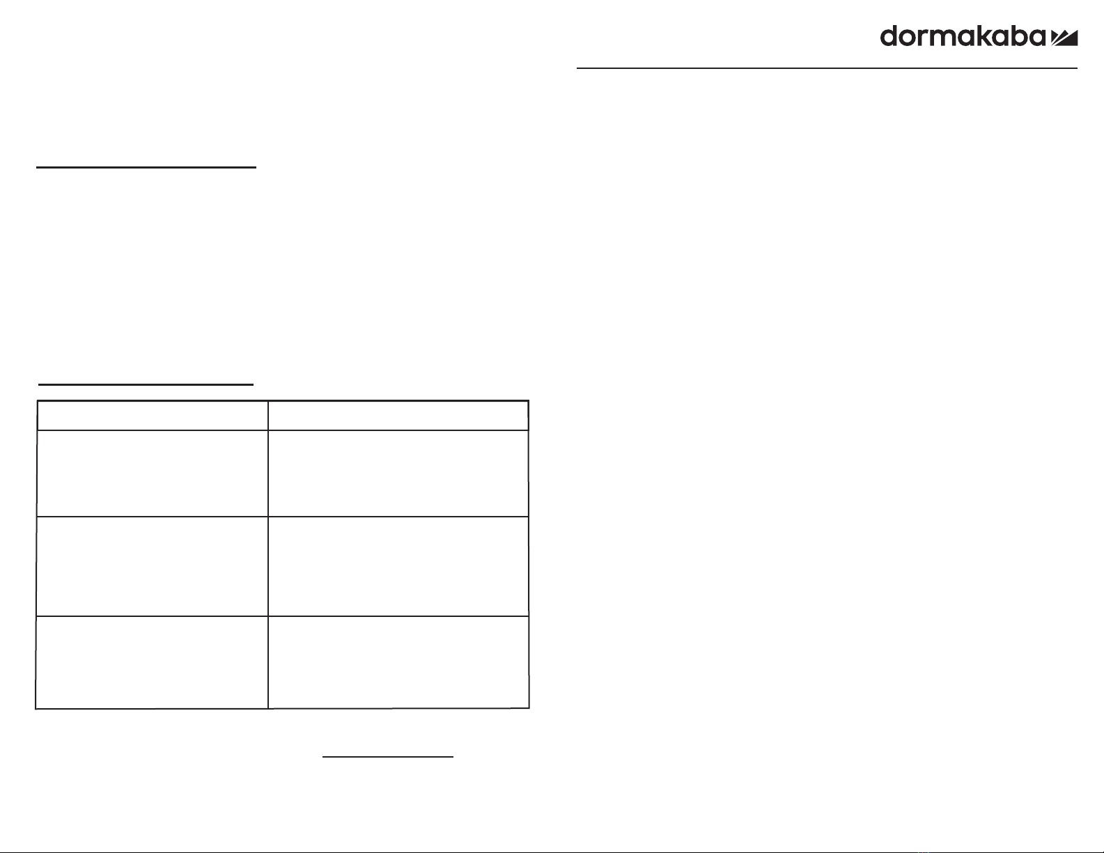
Troubleshooting Guide
Problem Solution
- Check AC and DC LED’s on power
supply board. Both should be on for
proper operation AC ON –GREEN,
DC ON - GREEN.
- If LED’s are not on, check AC power.
- Disconnect AC power, battery(s) and all
connected equipment IMMEDIATELY.
- Change voltage selection jumper to
desired voltage.
- Reconnect equipment & reapply AC
power.
- Check battery voltage.
No DC output from terminals.
Output voltage is not correct for the
connected equipment.
Trouble output relay is de-energized.
(Relay terminals are labeled shown
in the Normal, energized, “no trouble”
condition. Relays are energized when
no trouble is detected.
For Technical Support:
1-800-265-6630 or 519-621-7651 www.dormakaba.us
ISPS10-4 PCN17035
R08-19GR
RCI 10-4
Class 2 Power Limited
Power Supply Board c/w Charging
Installation and Specifications Manual
© 2019 dormakaba Canada Inc.
www.dormakaba.us • Phone: 1.800.265.6630 • Fax: 1.800.482.9795 • Email: [email protected]
INSTALLATION
RCI 10-4

Lead acid batteries are typically used for stand by power in security applications, as they
float charge well and have no usage memory. When float charged, they typically last
4-5 years. A precision power supply/charger will provide the proper voltage for any given
temperature regardless of load. This is what provides long battery life from the 10-4
supply board.
Fig. 2 – Power Supply Wiring Note: Maintain a minimum clearance of .25”
between power limited and non-power limited circuits.
Specifications
Note: For UL Listed Power
Supply UL294 Access Control
Performance levels:
Line Security - I
Endurance - I
Destructive Attack - I
Battery Standby - IV *
Input
✓AC input 120VAC/60Hz or
240VAC/50Hz * Selectable
✓Current Draw 216 Watts
✓AC visual indicator
Output
✓Typical Output Voltage
✓12 VDC Nominal, 12.5 VDC, 4A
UL recorded range for compatibility on battery for 12V configuration 9.7 - 13.2 VDC
✓24 VDC Nominal, 25.0 VDC, 4A
UL recorded range for compatibility on battery for 24V configuration 19.5 - 26.4 VDC
Note: Typical current measured without load.
✓4 Amps supply current at 12VDC
4 Amps supply current at 24VDC
✓Class II Power limited thermally protected DC output
✓Visual indication
Battery Backup
✓Fully integrated charging circuit
✓Automatic resetting battery over current protection
✓Reverse hookup protection 2A PTC
✓Average recharge current 125mA
✓LED visual indicator
Sealed lead-acid type battery, 12V | 24V, 4Ah-72Ah
For ULC-S318 compliance, the power supply battery fail line must be connected to
and monitored by a control panel trouble zone
* An 18AH battery was used for the UL evaluation.
Base Features
• Universal AC input from 120-240 VAC providing exceptional brownout protection
• Field selectable 12VDC or 24VDC output via jumpers
• Surge protected input and output voltage
• AC and DC visual indication
• Precise battery regulation for lead acid batteries
• Online batteries for no drop switch over on AC failure
• Form C relays to monitor AC failure and low battery condition
See specifications below for more details
Installation Instructions
1. Mount the supply board in an enclosure suitable for a power supply and battery,
as requirements dictate.
2. Make sure a conductive standoff is used with a star washer on the mounting
hole nearest the AC input. A good ground is required.
Note: 10-4 Supply board is for use in a controlled environment.
3. Run appropriate AC input wiring * to HIGH VOLTAGE terminals as marked (See Fig. 1).
4. Run wiring for devices to be powered as required and connect to DC output terminals.
Note: Ensure all wiring is of appropriate gauge for device being powered. All Power
Limited circuits must be routed a minimum of .25” from Non-power Limited circuits.
5. Set DC output voltage jumper to desired voltage PRIOR TO CONNECTING
BATTERY AND ENERGIZING AC INPUT VOLTAGE (See Fig. 2).
6. Apply power to AC input terminals and test DC outputs for proper operation.
7. Connect backup battery(s) to battery leads if required using the supplied cables
that are suitable to the installation.
Notes: Do not exceed maximum output of Power Supply 4A @ 12VDC, 4A @
24VDC.
Fig. 1
10-4 Power Supply
Circuit Board
* Note: There is a removable link
on the top of the power supply
board. This link is cut and
removed to convert to 240 VAC.
Once cut, there is no conversion
back to 120 VAC.
LNG
- DC +
DC
NO C NC
AC Fail
NO C NC
BAT Fail
AC
CUT FOR 230V
12V 24V
BATTERY
a minimum spacing of .25" from
NOTE:
non-power limited circuits.
All power limited circuits to have
Disconnect AC input prior to servicing
Safety Precautions
- +
LNG
- DC +
DC
NO C NC
AC Fail
NO C NC
BAT Fail
AC
CUT FOR 230V
12V 24V
non-power limited
Class I
AC main input
NEUTRAL
GROUND
LINE
Class II Power Limited
Non-Power Limited
*
This manual suits for next models
1
Popular Power Supply manuals by other brands


Ratio Electric
Ratio Electric AC16 User Instructions and Installation Guide

ASL INTERCOM
ASL INTERCOM PS 285 user manual

HARBACH ELECTRONICS
HARBACH ELECTRONICS PM-200 installation instructions

Vimar
Vimar ELVOX 6837 INSTALLATION DIAGRAMS

EPS Stromversorgung
EPS Stromversorgung 06230400 operating guide

Grundig
Grundig PSU 12 Service manual