Ratio Electric AC16 User manual
!
www.ratio.nl!
AC16-BASICKIT!/!!Version:)AC16-11)
User instructions and installation guide
AC16%POWER%SYSTEM%
AC16%BASIC%KIT%
1%
INTRODUCTION
We congratulate you on choosing your new marine shore power system.
This system is a member of a family of marine products from Ratio
Electric.
The AC16 shore power system provides a complete plug & play power
system for boats.
Read this manual prior to installing and using the system.%
SAFETY
WARNING!!This system has been designed and approved for installation by those
who has read and follow the instruction in this installation guide. A qualified
electrician is not required for installing the system. For this reason it is prohibited
to make any adjustments or modifications to the component parts of the system.
Changes could mean life threatening consequences to people in and around the
boat.!
WARNING!%This system must not be used without proper installation of the
electrical cabinet according to attached installation instruction.!
WARNING!%The power feed from the shore may not be connected to the boat
before the entire system has been installed in the boat. Connecting the power
from an outside source otherwise risks exposing people in and around the boat to
life threatening hazards.!
WARNING!%The shore power system’s protective earth must be electrically
connected with all the electrically conductive devices in the boat that have a
connection to earth, for example, via the water. Failure to do this will result in
immediate mortal danger to people in or around the boat in the event of a fault
to the electrical equipment connected to the shore power system.!
WARNING!%In order for the system to be able to provide protection against
personal injury in the event of a fault in one of the electrical devices connected to
the system, the system’s electrical cabinet must be a part of the installation.!
WARNING!%The electrical cabinet on shore, that the shore power cable is connected
to, should be regarded as a part of the installation. This is because the shore
power system’s protective earth must be able to provide protection against
personal injury in the event of a fault in any part of the system.%
WARNING!%Mains plugs are not the same in all countries and may have a different
earth. If the electrical system is connected to the land power supply through an
adapter cable then it must be carried out in accordance with the national heavy
current regulations.!
!
!
www.ratio.nl!
AC16-BASICKIT!/!!Version:)AC16-11)
2%
[DATUM]%
[UITGAVE]%
WARNING!%The utmost caution must be observed when using electrical tools in
conjunction with work close to or in direct connection to water. Electrical tools
that fall into the water represent mortal danger to people who are partially or fully
in the water.!
WARNING!%Installation may mean the need for holes in walls and parts of the
boat’s hull. As a result of this, the greatest possible caution must be observed
to ensure that no form of leakage occurs where peripheral lake or sea water
may penetrate your boat.!
NOTE!%The electrical cabinet must not be mounted more than 3 meters from the
power inlet.!
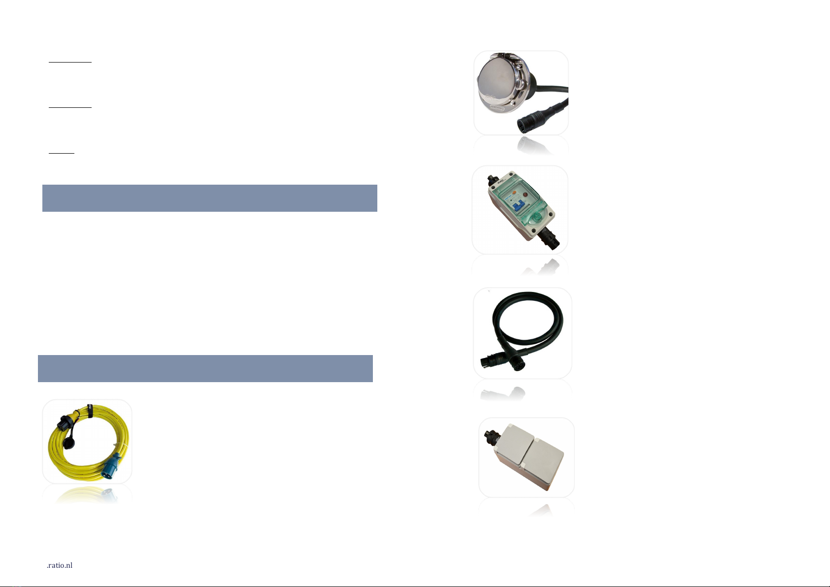
THE FOLLOWING PARTS ARE INCLUDED
v Shore%power%cord%set%p/n%2801%
v Stainless%steel%shore%power%inlet%16A%
v Internal%cable%1m%
v Electrical%cabinet%
v Internal%cable%2m%
v Wall%socket%
TECHNICAL DATA
SHORE POWER CORD SET p/n 2801
Dimension% % Ø%8,5%mm%
Temperature%range% -40˚C%-%+80˚C%
Insulation%class% % IP56%
Conductor%area% % 3%x%1,5mm2%
Voltage%%%250V%AC%
Current%%%10A%AC%
Length%%%15%m%
Weight%%%2,1%kg%
STAINLESS STEEL SHORE POWER INLET
Dimension% % Ø%90%mm%
Length%of%connection%cord%40%cm%
Insulation%class% % IP56%/%IP68%(cord)%
Conductor%area%cord%3%x%2,5mm2%
Voltage%%%250V%AC%
Current%%%16A%AC%
Weight%%%0,5%kg%
ELECTRICAL CABINET
INTERNAL CABLE
WALL SOCKET
Dimension% % Ø%11,3%mm%
Cable%lengths% % 1%m%/%2%m%
Insulation%class% % IP66%/%IP68%
Conductor%area%cord%3%x%2,5mm2%
Voltage%%%250V%AC%
Current%%%20A%AC%
Weight%%%0,22%kg%(1%m)%
0,43%kg%(2%m)%
Dimension%(L,W,H)%260%x%80%x%100%mm%
Insulation%class% % IP55%
Voltage%%%250V%AC%
Current%%%16A%AC%
Weight%%%0,56%kg%
Dimension%(L,W,H)%210%x%75%x%65%mm%
Insulation%class% % IP55%
Voltage%%%250V%AC%
Current%%%16A%AC%
Weight%%%0,32%kg%

!
www.ratio.nl!
AC16-BASICKIT!/!!Version:)AC16-11)
PREPARATIONS
A:%%%%55%mm%
B:%%%%4,5%mm%
C:%%%%50%mm%
3%
INSTALLATION OF THE SYSTEM IN THE BOAT
Lay out the system components and cables. Check that the length of the cables is
sufficient when taking the placement of the system apparatus into consideration.
%
ASSEMBLY OF POWER INLET
1. The electrical installation must be switched off during installation.
2. Install the power inlet according to the stated instruction and directions
in the manual.!
To install the power inlet, proceed as follows:
1. Make a cut out in ship’s hull using the outline drawings.
2. Position the gasket and inlet over the hull opening, align the mounting
holes and attach the inlet over the hull with screws. Install the inlet with
4mm stainless steel screws.
3.
SURFACE MOUNTING OF ELECTRICAL CABINET
!
Select a suitable place for fitting the electrical cabinet on a wall. Drill 2 holes of
4.5mm diameter and use 2 stainless steel screws with a flat bottom to mount the
electrical cabinet.
%
SURFACE MOUNTING OF DOUBLE WALL SOCKET
Select a suitable place for fitting the double wall socket. Drill 2 holes of 4.5mm
diameter and use 2 stainless steel screws with a flat bottom to mount the socket.
%
ASSEMBLY OF CABLES
Connect the internal cables to the system components, power inlet, electrical
cabinet and wall sockets. In order to release the cables connected to the system
devices, the accompanying dismantling tools must be used.
%
NOTE!%Ensure that the cables are relieved in the entry points to the devices when
assembling.!
NOTE!%Connect all live devices in the boat that have a connection to earth, for
example via the water, to the earth-connection block (X0) located on the bottom
of the electrical cabinet.!
SYSTEM OVERVIEW
AVAILABLE OPTIONS
CABLE SPLITTER 1:3
Dimension%(L,%W)% % 90%x%50%mm%
Voltage%%%250V%AC%
Current%%%20A%AC%
Weight%%%0,06%kg%

!
www.ratio.nl!
AC16-BASICKIT!/!!Version:)AC16-11)
!
4%
SOCKET OUTLET 1-WAY
Dimension%(L,W,H)%140%x%70%x%60%mm%
Insulation%class% % IP55%
Voltage%%%250V%AC%
Current%%%16A%AC%
Weight%%%0,18%kg%
SCHUKO OUTLET SOCKET
Dimension% % Ø%90%mm%
Insulation%class% % IP56%
Voltage%%%230V%AC%
Current%%%16A%AC%
Weight%%%0,35%kg%
SYSTEM DESCRIPTION
Description of the AC16 Shore power system for safe 230V installation in boats.
The shore power cable is connected at one end of the electrical cabinet on shore.
The other end is connected to the boat’s electrical power inlet. The internal
electrical cabinet is fed via an internal cable from the power inlet.
The electrical cabinet is fitted with a personal safety module containing earth fault
breaker (sensitivity, 30mA) and two-pole miniature circuit breaker (16A, C
characteristic).
The lamp indicates the voltage is present at the output connector.
!
LIABILITY
Ratio Electric is not liable for any damages to the boat resulting from the
installation of the shore power system. Furthermore, Ratio Electric is not liable for
any damages to the boat resulting from the careless handling of components in
the shore power system. Ratio Electric is not liable for any injuries to persons
arising from incorrect installation or caused by damaged system components.
!
LIMITED WARRANTY
Ratio Electric issues this limited warranty to the original purchaser of this
shore power system. This limited warranty is not transferable. Ratio
Electric guarantees this unit for two years from the date of purchase
against defect workmanship or material. The customer must return the
product together with the receipt of purchase to the point of purchase.
This warranty is void if components in the shore power system are
handled carelessly, opened or repaired by anyone other than Ratio
Electric or its authorized representative. Ratio Electric makes no warranty
other than this limited warranty and is not liable for any other costs other
than those mentioned above, i.e. no consequential damages. Moreover,
Ratio Electric is not obligated to any other warranty other than this
warranty.
!
DECLARATION OF COMPLIANCE
RATIO%ELECTRIC%B.V.,%Ambachtsstraat%12,%NL-3861%RH%Nijkerk,%The%Netherlands%
Hereby declare under sole responsibility that the component parts of the shore
power system that are covered by this declaration, comply with the following
standards:
• The shore power system in full: ISO 13297
• Shore power cable and marine inlet: IEC 60309-1
• Electrical cabinet: EN 60439-3
• Wall socket: IEC 60884-1
!
Nijkerk, 01.07.2010
Hans Snaak, managing director
!
Ratio Electric B.V.
Ambachtsstraat 12
NL-3861 RH Nijkerk
The Netherlands
Tel. +31-33-2452360
www.ratio.nl
This manual suits for next models
1
Popular Power Supply manuals by other brands

Videx
Videx 520MR Installation instruction

Poppstar
Poppstar 1008821 Instructions for use

TDK-Lambda
TDK-Lambda LZS-A1000-3 Installation, operation and maintenance manual

TDK-Lambda
TDK-Lambda 500A instruction manual

Calira
Calira EVS 17/07-DS/IU operating instructions

Monacor
Monacor PS-12CCD instruction manual


