Dictator RZ-24-05 Central User manual

© DICTATOR Technik GmbH • Gutenbergstr. 9 • 86356 Neusäß • Germany
Tel. +49(0)821-24673-0 • Fax +49(0)821-24673-90 • E-mail info@dictator.de • 20200513 Page 07.021.1
Technical Manual
RZ-24-05 Central
Technical Manual
RZ-24-05 Central
Page 07.021.01
You can find the current version of our manual on our website under «Downloads»:
https://en.dictator.de/products/hold-open-systems-fire-protection-doors/central-unit-rz-24/

© DICTATOR Technik GmbH • Gutenbergstr. 9 • 86356 Neusäß • Germany
Tel. +49(0)821-24673-0 • Fax +49(0)821-24673-90 • E-mail info@dictator.de • 20200513Page 07.021.2
Technical Manual
RZ-24-05 Central
Page 07.021.02
Table of Contents
Page
1. General Safety Instructions 07.021.03
2. General Regulations for Hold-Open Systems 07.021.04
a) Demands
b) Operational Life
3. Components of the DICTATOR Hold-Open System 07.021.04
4. Information about the RZ-24-05 Central 07.021.05
a) Membrane Keyboard
b) Technical Data of the RZ-24-05 07.021.06
5. Electrical Connection and Configuration of a 07.021.07
Hold-Open-System with RZ-24-05
a) Wiring Diagram
b) Terminal Assignment 07.021.08
c) Configuration of the DIP Switches 07.021.09
d) Assembly of the RZ-24-05 07.021.10
6. Placing into Operation of the Hold-Open System 07.021.10
7. Functioning and Adjusting Instructions for the
RZ-24-05 Central 07.021.11
a) Functions of the RZ-24-05
b) Faults 07.021.12

© DICTATOR Technik GmbH • Gutenbergstr. 9 • 86356 Neusäß • Germany
Tel. +49(0)821-24673-0 • Fax +49(0)821-24673-90 • E-mail info@dictator.de • 20200513 Page 07.021.3
Technical Manual
RZ-24-05 Central
Page 07.021.03
1. General Safety Instructions
General Safety
Instructions
The RZ-24-05 central is a power supply with integrated tripping device
for hold-open systems on fire and smoke protection doors
.
Only trained professionals may effect the installation; e.g. only a qualified
electrical technician may connect the power supply to the mains. To the
electrical installation following the power supply (safety extra-low voltage
24 VDC) apply the acknowledged technical regulations for electrical
installations. Only a professional trained by DICTATOR with an approval
authorisation may approve the system.
The relevant regulations must be observed for all work.
The operation of all components is only permitted in undamaged
condition.
The accident prevention regulations have to be respected.
The connection cables have to be installed in such a way that they cannot
be moved and are sufficiently protected against damage. Also here you
strictly have to adhere to the requirements of the respective operating
company. All components of the system, the cables and their connections
have to be clearly marked by the installation contractor.
If nothing else is required on site or by special regulations, the following
specifications have to be respected:
- All works on current circuits may only be effected in the de-
energized state.
Instructions for Wiring

© DICTATOR Technik GmbH • Gutenbergstr. 9 • 86356 Neusäß • Germany
Tel. +49(0)821-24673-0 • Fax +49(0)821-24673-90 • E-mail info@dictator.de • 20200513Page 07.021.4
Technical Manual
RZ-24-05 Central
2. General Regulations for Hold-Open System
2a) Demands
The device combinations "RZ-24" and "RZ-24-05" should be
mounted in the detection range of one of the fire detectors of the
respective door. If not, an additional detector is required.
In Germany, the installation of a hold-open system is regulated by the
general building inspection approval or type approval of the DIBt. For
European countries without national regulations, EN 14637 is used as
a guideline.
These regulations also govern:
- the mounting positions and number of fire detectors
- the position and design of the hand switch
- the acceptance test (first placing in service) and marking
- the recurring functional tests and maintenance
- the requirements for the qualification of the persons testing
and maintaining
The documents are available under www.dictator.de. The general type
approval DIBt also includes all permissible device combinations.
For further instructions on installation, use, maintenance, functional
testing and servicing as well as documentation, please refer to our
operating manual for hold-open systems, which is available to our
authorised specialists for DICTATOR hold-open systems.
2b) Operational life To ensure the correct functioning of the hold-open system, the DICTA-
TOR smoke and heat detectors have to be replaced after a maximum
of 8 years of operational life. In Germany the DIN 14677 regulates the
replacement obligation of fire detectors in hold-open systems.
3) Components of a
DICTATOR Hold-Open
System with
RZ-24-05
The DICTATOR hold-open system may comprise a maximum of 20 smoke
and/or heat detectors. (ATTENTION: observe the maximum output load
of the RZ-24-05 central!).
Components:
- RZ-24-05 central with power pack, part no. 040563
- RM 4000 smoke detector or WM 4000 heat detector with base, part
no. 040860SET or 040861SET
- Resistor 3.9 kΩ(included in the delivery of the RZ-24-05)
- Magnet (DICTATOR electromagnets EM GD 50 to EM GD 70 - see
separate catalogue pages)
- Push button of the RZ-24-05 central, further push button switches can
be connected in the detector loop, e.g. part no. 040005
Page 07.021.04

© DICTATOR Technik GmbH • Gutenbergstr. 9 • 86356 Neusäß • Germany
Tel. +49(0)821-24673-0 • Fax +49(0)821-24673-90 • E-mail info@dictator.de • 20200513 Page 07.021.5
Technical Manual
RZ-24-05 Central
4. Information about the RZ-24-05 Central
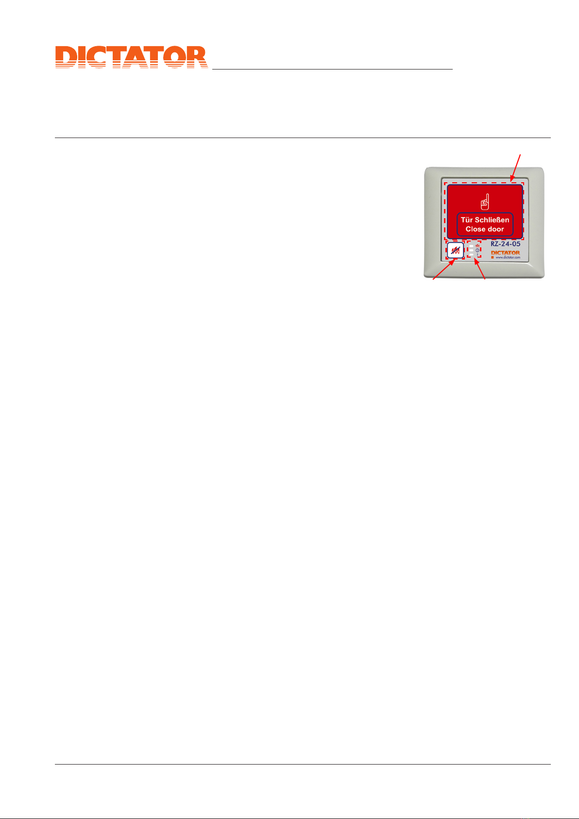
4a) Membrane
Keyboard Key
Close door
Detection loop triggered
Detection loop ready
Error
Key Reset
General Information
The membrane keyboard is slightly heated by the underlying electronics.
Thus the foil surface feels warm to the touch. When using the controller
in cool rooms, the heating of the keyboard prevents the formation of
condensation water. The controller is only suitable for deep-freeze areas
if it is housed in an additional enclosure with an additional heater.
Key "Close door"
The "Close door" key is a 35 x 47 mm red flat key without button click,
which has two functions:
Function 1: Test activation of the fire detection loop and closing of
the connected closing device.
Function 2: Resetting the triggered detectors by switching off the
loop voltage.
After pressing the button, the detection loop can only be reset after a
waiting period of 3 s.
Key "Reset"
The "Reset" key is a 10 x 10 mm white key with button click, which resets
the central unit when pressed. The reset only works if the connected
detectors are not triggered and ready for operation and the 3 s waiting
period after pressing the "Close door" button has expired.
Ill. 1
Page 07.021.05

© DICTATOR Technik GmbH • Gutenbergstr. 9 • 86356 Neusäß • Germany
Tel. +49(0)821-24673-0 • Fax +49(0)821-24673-90 • E-mail info@dictator.de • 20200513Page 07.021.6
Technical Manual
RZ-24-05 Central
4. Information about the RZ-24-05 Central - cont.
Supply voltage 85 VAC - 264 VAC
Power consumption about 14 W, own consumption about
40 mA
Secondary output voltage 24 VDC ±10 %
Secondary total load 0.5 A (supply of fire detectors, electro-
magnets and other consumers)
Operating temperature 0 °C to +40 °C
Max. number of detectors 20
Power consumption of the
detection loop
Alarm: I > 12 mA
Interruption: I < 3 mA
Short circuit current: max. 45 mA
Quiescent current: 4.5 mA
Line tension: Ulin = 20.5...21.4
LED indicators Green LED is on: detection loop is
ready.
Red LED is on: detection loop is
triggered.
Yellow LED is on/flashes: there is a
disturbance.
IP rating IP 30
4b) Technical Data
RZ-24-05
ATTENTION
Some parts inside the casing are
energized with hazardous voltage
during operation! May be opened
only by professionals when being
de-energized (the power supply of
the RZ-24-05 is cut!!)
IMPORTANT: In total the RZ-24-05 central provides 0.5 A for the supply
of the connected fire detectors, magnets etc.
In case the maximum power consumption is exceeded, the RZ-24-05
will automatically switch off. This also happens when it is overheated!
Page 07.021.06

© DICTATOR Technik GmbH • Gutenbergstr. 9 • 86356 Neusäß • Germany
Tel. +49(0)821-24673-0 • Fax +49(0)821-24673-90 • E-mail info@dictator.de • 20200513 Page 07.021.7
Technical Manual
RZ-24-05 Central
RM/WM 4000
RM/WM 4000
RM/WM 4000
3k9
5a) Wiring Diagram The following wiring example applies when the components of point 3
are used.
5. Electrical Connection and Configuration of the
Hold-Open System with RZ-24-05
Ill. 2
External closing signal 24 V/5 mA
optional Flash buzzer
(24 VDC, max. 300 mA)
(optional)
Electromagnets
(24 VDC, in total
max. 240 mA)
Push button
switch
Power pack
Power pack
optional
Page 07.021.07

© DICTATOR Technik GmbH • Gutenbergstr. 9 • 86356 Neusäß • Germany
Tel. +49(0)821-24673-0 • Fax +49(0)821-24673-90 • E-mail info@dictator.de • 20200513Page 07.021.8
Technical Manual
RZ-24-05 Central
Function Description
1 Detection loop (+) output; (terminating resistor 3.9 kΩ)
2 Detection loop (--) output; (terminating resistor 3.9 kΩ)
3 -24 V output Power supply for fire detectors
and/or manual release with LED
indication.
4 Ground (0 V)
5 Ground (0 V) -
6 Output HM (+) free-wheeling diode present
7 Output HM (--) ground 0 V
8 Output WS (--) warning signal; ground 0 V
9 Output WS (+) warning signal; free-wheeling diode
present
10 24 V operating
voltage
connect power supply output (+)
11 Ground (0 V) connect power supply output (--)
12 External input input central closing or external
reset (+)
13 Ground (0 V) -
14 External input input central closing or external
reset (+)
5b) Terminal Assignment
5. Electrical Connection and Configuration of the
Hold-Open System with RZ-24-05 - cont.
The RZ-24-05 has 14 terminals. The maximum permissible wire thickness
is 0.75 mm². The terminals may only be loosened with a special tool,
part no. 040565, which is available separately. A normal screwdriver
will damage the terminals!
Page 07.021.08

© DICTATOR Technik GmbH • Gutenbergstr. 9 • 86356 Neusäß • Germany
Tel. +49(0)821-24673-0 • Fax +49(0)821-24673-90 • E-mail info@dictator.de • 20200513 Page 07.021.9
Technical Manual
RZ-24-05 Central
DIP switch 1
When DIP switch 1 is set to OFF (factory setting), a tripping is stored.
This means that a manual push button release is not automatically reset
and the reset button must be operated manually.
DIP switch 1 in position ON realizes the automatic reset mode. This
means that a tripping is automatically reset after 3 s when the detection
loop is ready.
DIP switch 2
The DIP switch 2 in position OFF (factory setting) realizes the central
closing via the external input. For this purpose, 24 V are briefly applied
to the input. Central closing can be used to close doors (only with
electromagnets) without triggering the detection loop of the RZ-24-05.
This function is not a closing in case of fire, but only realizes the closing
of the fire and smoke protection closures, e.g. at the end of the working
day. The electromagnet output is switched off for approx. 3 s when the
24 V are applied to the external input.
The DIP switch 2 in position ON enables an external reset of the central
via the external input 12 or 14.
5c) Configuration of the
DIP Switches
5. Electrical Connection and Configuration of the
Hold-Open System with RZ-24-05 - cont.
DIP switches
for the
operating
modes
Control unit rear side
Ill. 3
Page 07.021.09

© DICTATOR Technik GmbH • Gutenbergstr. 9 • 86356 Neusäß • Germany
Tel. +49(0)821-24673-0 • Fax +49(0)821-24673-90 • E-mail info@dictator.de • 20200513Page 07.021.10
Technical Manual
RZ-24-05 Central
(1)
(2) (3)
- After connecting all components in the
RZ-24-05 central, put the cover back on.
- Switch on the power supply:
With correct connection => the red LED
(3) on the housing lights.
- Reset the central unit with the RESET
button (2) on the housing cover.
Now the system is ready for ope-
ration.
6) Placing the Hold-Open
System into Operation
Ill. 4
Front
5d) Assembly of the
RZ-24-05
Ill. 5
© DICTATOR Technik GmbH • Gutenbergstr. 9 • 86356 Neusäß • Germany
Tel. +49(0)821-24673-0 • Fax +49(0)821-24673-90 • E-mail info@dictator.de • 20200513 Page 07.021.11
Technical Manual
RZ-24-05 Central
(1)
(1)
(2) (3)
7. Functioning/Adjusting Instructions of the RZ-24-05
-RESETTING the complete hold-
open system after an alarm:
Firstly reset the fire detectors by means
of the hand release key (1) on the
cover of the casing. For this purpose
press the key longer than 3 s. Now the
entire system can be switched back into
operation with the RESET button (2) of
the central.
7a) Functions of the
RZ-24-05
Ill. 6
LED indicator "Trip"
The "Trip" LED indicator lights up red when the RZ-24-05 detector loop
is tripped. The "electromagnet" output is switched off, the "warning
light" output is switched on.
LED indicator "Ready"
The "ready" LED indicator lights up green when the RZ-24-05 detector
loop is ready (not triggered). The "electromagnet" output is switched
on, the "warning light" output is switched off.
LED indicator "Error"
The "Error" LED indicator lights up or flashes yellow. A permanently
yellow LED indicates a serious defect of the RZ-24-05. A yellow flashing
LED indicates various other errors: The individual errors are indicated
by the flashing LED one after the other. The messages are separated by
a pause of 1 second (LED off).
1 x flashing = undervoltage error, i.e. the operating voltage has dropped
below 15 V.
2 x flashing = flash memory error of the controller.
3 x flashing = output electromagnet overload or open.
A short flash of the LED "Error" when switching on the controller is normal
and serves to test the display.
Example: Undervoltage error and flash memory error are pending:
1 x yellow flashing, pause 1 s, 2 x yellow flashing, pause 1 s, 1 x yellow
flashing, pause 1 s and so on.
© DICTATOR Technik GmbH • Gutenbergstr. 9 • 86356 Neusäß • Germany
Tel. +49(0)821-24673-0 • Fax +49(0)821-24673-90 • E-mail info@dictator.de • 20200513Page 07.021.12
Technical Manual
RZ-24-05 Central
Protronic
Z-6.510-2435
VDS
7b) Faults Error Measure
Detection loop cannot be
reset
Check whether the RZ-24-05 can be
reset with a 3.9 kΩ resistor on terminals
1 and 2. If not, check whether the
control module is correctly inserted in the
terminal board. If the problem persists,
replace the control module.
If resettable with a 3.9 kΩ resistor on
terminals 1 and 2, check the external
detection loop step by step. Is a 3.9 kΩ
resistor in the last detector? Is the manual
push button reset and is a correct contact
used?
Error LED lights up
permanently yellow
Voltage from power supply too low?
Please measure.
External load too high?
Replace the power supply unit if
necessary.
Control module defective, replace it.
Key "Close door" does
not work
Replace the control module.
Key "RESET" does not
work
Replace the control module
Electromagnets don't work Check the cable path from the terminal
board to the electromagnets.
Replace the terminal board.
Warning signal does not
work
Check the cable path from the terminal
board to the warning signal device.
Replace the terminal board.
7. Functioning/Adjusting Instructions RZ-24-05 - cont.
Other manuals for RZ-24-05 Central
1
Table of contents
Other Dictator Power Supply manuals


