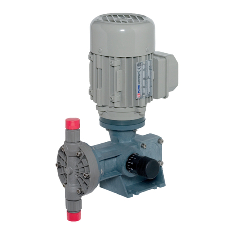
Doseuro SR Series User manual

EDITION 2020
Reciprocating dosing pump
with spring return
USE AND MAINTENANCE MANUAL
TRANSLATION OF
ORIGINAL
INSTRUCTIONS
EN
Series
SR
mod. APISTON
mod. DDIRECT DIAPHRAGM
mod. BHYDRAULIC
DIAPHRAGM
mod. BR HYDRAULIC
DIAPHRAGM AND
RECIRCULATION
VALVE
mod. SD SANDWICH DUAL
DIAPHRAGM WITH
INTERPOSED FLUID
AND RECIRCULATION
VALVE
SD
BR
ATTENTION:
Industrial machinery for professional use.
These instructions are for qualified personnel
B
D
A

XMPE0PCG125NST020 1st edition - 2020
2/76
DOC. NO.:
XMPE0PCG125NST020
Rev.
0
LANGUAGE:
EN
Date:
04/06/2020
Drawn up by:
Gianluigi VENERONI
Checked by:
Luca FUMAGALLI
Repl. On:
-
Rev.
Description
Checked by
Date
01
Correzione diametro 10->12 pag.46
L. FUMAGALLI
26/01/2021
02
B-BR-SD 125-18 diametro membrana 70->50
L. FUMAGALLI
28/01/2021
03
Eliminato logo ISO pagina 8
L. FUMAGALLI
09/04/2021

XMPE0PCG125NST020 1st edition - 2020
3/76
Table of contents
1 - PREFACE ..............................................................................................................................................................6
1.1 -GENERAL PRESCRIPTIONS......................................................................................................................................6
1.2 -TECHNICAL ASSISTANCE........................................................................................................................................6
1.3 -ELECTRIC MOTORS ..............................................................................................................................................6
1.4 -LIABILITY ..........................................................................................................................................................6
DECLARATION OF CONFORMITY...............................................................................................................................................8
2 - REQUIREMENTS FOR USE ....................................................................................................................................9
2.1 -GENERAL SAFETY WARNINGS .................................................................................................................................9
2.2 -SYMBOLS..........................................................................................................................................................9
3 - SAFETY STANDARDS DURING USE .....................................................................................................................10
3.1-CLOTHING.......................................................................................................................................................11
3.2 -MINIMUM QUALIFICATION OF PERSONNEL..............................................................................................................11
4 - USING THE DOSING PUMPS...............................................................................................................................12
4.1 -INTENDED USE .................................................................................................................................................12
4.2 -INTENDED AND UNINTENDED PUMP USE.................................................................................................................12
4.3 -USAGE CONDITIONS ..........................................................................................................................................12
4.4 -MACHINE DESCRIPTION......................................................................................................................................12
4.4.1 - Operating principle...............................................................................................................................12
4.4.2 - Formula of the theoretical flow rate .....................................................................................................13
4.4.3 - Effective flow rate.................................................................................................................................14
4.5 -PUMP DESCRIPTION ..........................................................................................................................................14
4.6 -DOSING PUMPS SR SERIES ..................................................................................................................................14
4.6.1 - Piston dosing pumps type SR A .............................................................................................................15
4.6.2 - Direct diaphragm dosing pumps type SR D............................................................................................15
4.6.3 - Type SR B Hydraulic diaphragm dosing pumps......................................................................................16
4.6.4 - Type SR BR Hydraulic diaphragm dosing pumps....................................................................................16
4.6.5 - Hydraulic diaphragm dosing pumps type SR SD ....................................................................................17
4.6 -IDENTIFICATION PLATE .......................................................................................................................................17
4.7 -SOUND VIBRATION............................................................................................................................................18
4.8 -MAXIMUM OPERATING TEMPERATURE PUMP HEADS.................................................................................................20
4.9 -TECHNICAL DATA ..............................................................................................................................................21
4.9.1-Pump technical data...............................................................................................................................21
5 –TRANSPORT AND STORAGE ..............................................................................................................................29
5.1 -PUMP DELIVERY ...............................................................................................................................................29
5.2 -LIFTING AND HANDLING .....................................................................................................................................29
5.3 -MATERIAL STORAGE..........................................................................................................................................29
5.3 -HANDLING FOR INSTALLATION .............................................................................................................................30
6 - PUMP INSTALLATION ........................................................................................................................................30
6.1 -OPTIMUM INSTALLATION CONDITIONS...................................................................................................................30
Altitude: ..........................................................................................................................................................30
Temperature: ..................................................................................................................................................30
6.2 -PUMP LOCATION ..............................................................................................................................................30
7 - CONNECTION OF THE PUMP TO THE SYSTEM PIPES..........................................................................................31
7.1 -BLOCK REMOVAL..............................................................................................................................................31
7.2 -CONNECTION TO THE SUCTION PIPE.......................................................................................................................31
7.3 -DISCHARGE PIPE CONNECTION .............................................................................................................................33
7.4 -LEAK RECOVERY................................................................................................................................................33
8 - DESCRIPTION OF STANDARD PLANT ACCESSORIES ...........................................................................................34

XMPE0PCG125NST020 1st edition - 2020
4/76
8.1 –Pulsation dampener ............................................................................................................................... 34
8.2 - Pressure gauge ....................................................................................................................................... 34
8.3 - Safety relief valve.................................................................................................................................... 34
8.4 - Sampling or draining............................................................................................................................... 34
8.5 - Filter ....................................................................................................................................................... 34
8.6 - Flowmeter............................................................................................................................................... 34
8.7 - Back pressure valve................................................................................................................................. 35
8.8 - Shut-off valve in the discharge pipe......................................................................................................... 35
9 - LUBRICATION.................................................................................................................................................... 35
10 - ELECTRICAL CONNECTION............................................................................................................................... 36
10.1 -MOTOR CONNECTION ..................................................................................................................................... 36
11 - PUMP ADJUSTMENT ....................................................................................................................................... 37
11.1 -STROKE VARIATION WITH MANUAL SYSTEM .......................................................................................................... 37
11.2 -STROKE VARIATION WITH SERVO CONTROL ........................................................................................................... 37
12 - OPTIONAL ACCESSORIES.................................................................................................................................38
12.1 -CONTROL WITH INDUCTIVE PROXIMITY SENSOR ..................................................................................................... 38
13 - PROCEDURE BEFORE START-UP ...................................................................................................................... 38
13.1 -COMMISSIONING ...........................................................................................................................................38
13.2 -PROBLEMS UPON COMMISSIONING .................................................................................................................... 38
14 - MAINTENANCE................................................................................................................................................ 39
14.1 –PUMP MAINTENANCE,REPAIRS.........................................................................................................................39
14.2 -PROCEDURES FOR MAINTENANCE INTERVENTION ...................................................................................................39
14.3 -RESIDUAL RISKS ............................................................................................................................................. 40
14.4 -SPARE PARTS LIST...........................................................................................................................................40
14.5 -PREVENTIVE MAINTENANCE..............................................................................................................................40
14.5.1 - Noisy mechanics with vibrations ........................................................................................................ 40
14.5.2 - Electric motor..................................................................................................................................... 40
14.5.3 - Checking the flexible coupling ............................................................................................................ 40
14.5.4 - Checking the pump flow rate.............................................................................................................. 41
14.5.5 - Pressure ............................................................................................................................................. 41
14.6 -ROUTINE MAINTENANCE..................................................................................................................................41
14.7 -VALVE UNIT CLEANING .................................................................................................................................... 41
15 - MAINTENANCE OF DOSING PUMP HEADS ...................................................................................................... 42
15.1- MAINTENANCE OF PISTON PUMP HEADS A............................................................................................................42
15.1.1 - Piston seal check and replacement..................................................................................................... 42
15.1.2 - Pump head with gasket washing........................................................................................................ 42
15.1.3 - Replacement of the "PTFE" gasket pack ............................................................................................. 43
15.1.4 - adjustment and compression of "PTFE" gaskets ................................................................................. 43
15.1.5 - Intermediate maintenance................................................................................................................. 43
15.2 -MAINTENANCE OF DIRECT DIAPHRAGM PUMP HEADS TYPE D....................................................................................44
15.3 -MAINTENANCE OF TYPE BHYDRAULIC DIAPHRAGM PUMP HEADS .............................................................................. 45
15.3.1 - Operations to be performed on the Type B pump head....................................................................... 45
15.3.2 - Pump head disassembly and diaphragm replacement........................................................................ 45
15.3.3 - Piston disassembly and reassembly.................................................................................................... 45
15.3.4 - Filling the oil reservoir ........................................................................................................................ 46
15.4.5 - Routine maintenance ......................................................................................................................... 47
15.4 -MAINTENANCE OF TYPE BR HYDRAULIC DIAPHRAGM PUMP HEADS ............................................................................48
15.4.1 - Operations to be performed on the Type BR pump head .................................................................... 48
15.4.2 - Recirculation vessel calibration and oil filling ..................................................................................... 48
15.4.3 - Pump head disassembly and diaphragm replacement........................................................................ 49

XMPE0PCG125NST020 1st edition - 2020
5/76
15.5 -MAINTENANCE OF TYPE SD HYDRAULIC DIAPHRAGM PUMP HEADS.............................................................................50
15.5.1 - Operations to be performed on the type SD pump head......................................................................50
15.5.2 - Signal and alarm instruments .............................................................................................................50
15.5.3 - Periodic check of the pump head ........................................................................................................51
15.5.4 - Pump head disassembly and diaphragm replacement ........................................................................51
15.5.5 - Pump head disassembly operation......................................................................................................51
15.5.6 - Pump head reassembly operation.......................................................................................................52
15.5.7 - Diaphragm reload and achieving vacuum ...........................................................................................53
16 - BR-SD PUMP HEADS RECIRCULATION VESSEL CALIBRATION...........................................................................54
16.1 -RECIRCULATION VESSEL TYPE VR 4–6(VR 10 AP) CALIBRATION..............................................................................54
16.2 -RECIRCULATION TANK TYPE VR 10-15-25 (VR 10 HP) CALIBRATION.........................................................................55
16.3 -RECIRCULATION TANK TYPE VR 40 CALIBRATION....................................................................................................57
16.4 -BR-SD PUMP HEADS RECIRCULATION VESSEL TABLES...............................................................................................59
17 - DECOMMISSIONING THE PUMP ......................................................................................................................61
17.1 -DISPOSAL OF COMPONENTS AND HARMFUL SUBSTANCES.........................................................................................61
18 - REPAIR ACCOUNT MAINTENANCE...................................................................................................................61
18.1 -PRACTICAL RECOMMENDATIONS FOR PUMP RECLAMATION.......................................................................................61
19 - USER INFORMATION .......................................................................................................................................62
20 - DOSING PUMPS TROUBLESHOOTING TABLES .................................................................................................63
20.1 -ATYPE PISTON PUMPS TROUBLESHOOTING TABLE...................................................................................................63
20.2 -TROUBLESHOOTING TABLE FOR DIRECT DIAPHRAGM PUMPS TYPE D............................................................................64
20.3- BTYPE PUMPS WITH HYDRAULIC DIAPHRAGM TROUBLESHOOTING TABLE ......................................................................65
20.4- BR-SD TYPE PUMPS WITH HYDRAULIC DIAPHRAGM TROUBLESHOOTING TABLE...............................................................66
21 - ATTACHED FORMS...........................................................................................................................................69
DOSING PUMP MAINTENANCE SHEET ............................................................................................................69
SPARE PARTS REQUEST FORM ........................................................................................................................70
DECLARATION OF RECLAMATION BY THE CUSTOMER ....................................................................................71
AUTHORISED ACCEPTANCE NO.:.....................................................................................................................73

XMPE0PCG125NST020 1st edition - 2020
6/76
1 - PREFACE
1.1 - General prescriptions
Thank you for having chosen this product. Please read this manual carefully before installing the dosing
pump, paying particular attention to the safety warnings flagged by the pictograms.
Compliance with the reported standards and requirements allow for safe use and the appropriate
interventions.
The use and maintenance manual is an integral part of the machine and must be readily available to the
use and maintenance personnel; therefore, keep it intact and in a safe place (protected by transparent
and watertight packaging to prevent deterioration). The manual must always accompany the machine,
including any changes in ownership.
No responsibility is accepted for translations into other languages that do not comply with the original
meaning. The manual reflects the state of the machine at the time of supply, and therefore cannot be
considered inadequate at a later date due to subsequent updates dependent on new studies or
experiences.
The Company DOSEURO S.r.l. reserves the right to update the production and manuals without any
obligation to inform users of previously supplied machinery.
1.2 - Technical assistance
Routine and extraordinary maintenance must take place in accordance with the instructions contained in
this manual. For any type of technical assistance and for requesting spare parts, contact the DOSEURO
headquarters, reseller or plant engineer directly, referring to the data from the rating plate on the pump:
✓Pump model.
✓Serial number.
✓Year of manufacture.
If pump maintenance is not carried out in a manner that is conforming to the instructions provided, or in a
way that jeopardises its integrity or modifies its characteristics, the manufacturer is no longer liable with
regard to the safety of persons and defective pump operation.
DoseuroS.r.l. Via G. Carducci, 141 - 20093 Cologno Monzese (Mi)
Sales Office:tel. 0227301324 r.a. –fax 0226700883
Web: www.doseuro.com
1.3 - Electric motors
As per standard, the pump is supplied with an electric motor conforming to the requirements contained in
the customer order and compatible with the intended use.
DOSEURO S.r.l. rejects any liability for damage caused by the motor and the pump when used in
conditions that are different from those defined in the order.
If the motor is subcontracted from the customer, he must transmit related technical conformity
documentation to DOSEUROS.r.l, that declines any liability.
If the pump is supplied without the motor, DOSEUROS.r.l. declines any liability resulting from an incorrect
motor selection and installation by the customer. If the pump is supplied with a bare shaft, the motor must
be mounted in accordance with the provisions of DOSEURO S.r.l and the Customer shall be responsible
for the EC declaration of the complete machine.
1.4 - Liability
Failure to comply with the instructions contained in this use and maintenance manual relieves the
manufacturer of any liability.
The company declines any liability in case of:
-use of the pump not in accordance with national safety and accident prevention regulations;
-operations performed by unqualified personnel;
-incorrect installation;
-tampering with the product;
-incorrect or failure to comply with the instructions in the manual;
-incorrect or failure to comply with the instructions on the identification labels applied to the units;

XMPE0PCG125NST020 1st edition - 2020
7/76
ATTENTION!
The instructions provided in this manual do not replace but supplement the obligations of current
legislation regarding safety standards.
This manual refers to products marketed at the time of its issue. DOSEURO reserves the right to modify
the data in this manual at a later date without prior communication.
Consult the Company directly for any information that is not understood or not deducible from the
following pages. DOSEURO S.r.l.
ANY MODIFICATION NOT AUTHORISED BY THE MANUFACTURER, WHICH ALTERS THE
EXPECTED FUNCTIONALITY ADAPTING THE RISKS AND/OR GENERATING ADDITIONAL
ONES, WILL BE THE FULL RESPONSIBILITY OF THOSE EXECUTING THEM.
THESE CHANGES, IF EXECUTED WITHOUT THE MANUFACTURER'S AUTHORISATION,
SHALL ALSO VOID ANY ISSUED GUARANTEE AND INVALIDATE THE DECLARATION OF
CONFORMITY FORESEEN BY THE MACHINERY DIRECTIVE

XMPE0PCG125NST020 1st edition - 2020
8/76
DECLARATION OF CONFORMITY
(Annex IIA DIR. 2006/42/EC)
The company DOSEUROS.r.l.
with headquarters in Via G. Carducci, 141 - 20093 Cologno Monzese (Mi)
Declares under its own responsibility that the products belonging
to the following sales category.
SPRING RETURN DOSING PUMPS
Series: SR Model: A-B-BR-SD-D
Comply with the requirements of:
Directive 2006/42/EC Machinery Directive (and subsequent amendments)
Directive 2014/30/EU Electromagnetic compatibility
Directive 2014/35/EU Low voltage directive
Directive 2011/65/EU RoHS II
And with the following Harmonised Safety Standards:
UNI EN 12100:2010 Safety of machinery - General principles for design - Risk
assessment and reduction
IEC EN 60204-1:2006 Electrical equipment of machines
+ Annex 1:2009
The technical file is kept at our headquarters.
PLACE AND DATE: Cologno Monzese –06/11/2019
Signature and position of the declarant
Technical Management Director
LUCA FUMAGALLI
Via G. Carducci, 141
20093 Cologno Monzese (Mi)
Il certificato è prodotto con dispositivo elettronico ed è valido senza firma. The certificate is produced with EDP and valid without
signature
Via G. Carducci, 141
20093 Cologno Monzese (Mi)
Tel. 0227301324
www.doseuro.com

XMPE0PCG125NST020 1st edition - 2020
9/76
2 - REQUIREMENTS FOR USE
2.1 - General safety warnings
The supplemental pump instruction manual contains the fundamental points that
characterise the installation, operation and maintenance of pumps intended for use
in dosing liquids. It is therefore necessary for the installer, specialised service
personnel or the plant manager to carefully read the manual before installation and
start-up.
It is not sufficient to only follow the general safety instructions contained; one must also follow the specific
safety provisions and provisions contained in the use and maintenance manual related to the
manufacture series of the pump in question.
2.2 - Symbols
It is necessary to draw attention to the symbols used to highlight residual risks in this publication that are
connected to intended pump use.
To read and use the symbols correctly, we recommend referring to standard EN ISO 7010 graphical
symbols -- safety colours and safety signs -- Registered safety signs.
Hereunder are pictograms that highlight the main warnings and the behaviour the operator must adopt
when the symbol is indicated, in order to carry out his functions in total safety.
TABLE OF SYMBOLS EN ISO 7010
General mandatory action sign
To signify a mandatory action
Refer to the instruction manual/booklet
To signify that the instruction manual/booklet must be read
Wear ear protection
To signify that ear protection must be worn
Wear eye protection
To signify that eye protection must be used
Connect an earth terminal to the ground
To signify that an earth terminal must be connected
Wear safety footwear
To signify that safety footwear must be worn
Wear protective gloves
To signify that protective gloves must be worn
Wear protective clothing
To signify that protective clothing must be worn
Wear head protection
To signify that head protection must be worn
Wear respiratory protection
To signify that respiratory protection must be worn

XMPE0PCG125NST020 1st edition - 2020
10/76
DANGER!
ATTENTION!
RISK OF SERIOUS INJURIES!
TABLE OF SYMBOLS EN ISO 7010
Disconnect before carrying out maintenance or repairs
To signify that the machine or the equipment, which is not connected to the mains
by a plug, has to be disconnected from all sources of power before carrying out
maintenance or repairs
General warning sign
To signify a general warning
Warning; electricity
To warn of electricity
Warning; Hot surface
To warn of a hot surface
Warning; Corrosive substance
To warn of a corrosive substance
Warning; Risk of crushing hands
To warn of a closing motion of mechanical parts of equipment
ATTENTION!
It means that not following the safety rules can cause slight injury
to persons or damage to property.
DANGER!
It means that not following the safety rules can cause injury to
persons or damage to property.
RISK OF SERIOUS INJURIES!
It means that non-compliance with the safety standards
may cause serious personal injuries or damage to
property.
The operations referred to by these symbols must be carried out by professionally qualified personnel, with specific
skills for areas characterised by the presence of a potentially explosive atmosphere.
Failure to comply with the regulations may cause serious personal injuries or damage to property.
3 - SAFETY STANDARDS DURING USE
The purpose of this section is to illustrate pump use with respect to essential safety standards.
To use the dosing pump, the installer and operator must carefully read this section in order to guarantee
the safety of operators and the surrounding property.
DOSEURO declines any liability in case of personal injury or property damage deriving from the
incorrect or improper use of the pump.
If the pump is to be used for other processes the customer must, to be able to re-use it, request
information from our engineering department on the compatibility of the materials for correct use.
The main risks connected with pump use are:
RESIDUAL RISK!

XMPE0PCG125NST020 1st edition - 2020
11/76
COMPULSORY CLOTHING SIGNS
ATTENTION!
➢MECHANICAL:
•Collision, compression of certain parts of the body, especially head and limbs.
•Fall or projection of objects.
•Dangerous vibrations that may harm the operator, damage the machine and the environment
it is installed in.
•Clothes accidentally being inserted into moving parts.
•Heat developed by pump operation or overheating.
➢ELECTRICAL:
•Contact with power supply and distribution cables.
•Metal elements powered due to electrical malfunction.
•Static electricity.
➢PLANT:
•Breakage or leakage from the system downstream of the pump with corrosive liquid outflow with
corrosion of the outer parts of the dosing pump (it is advisable to avoid passing the pressurised
discharge pipe above the pump. Should this not be possible, provide a cover).
•Dosed liquid solidified or frozen in the pipes due to its nature or because the system has been
stationary for a certain period of time and no proper washing of the piping has been performed,
or due to winter season with very low temperatures that cause general freezing of liquid
substances. Always check the system before start-up after it has been stopped for a long period
of time (e.g. weekend with system stopped on Saturday and Sunday and restarting on Monday
morning).
3.1 - Clothing
Before carrying out any type of intervention on the pump or system, the operator must wear suitable
protections according to current law regulation standards (81/08) for preventing contact with pumped
liquid, such as:
Protective gloves, protection goggles, breathing masks, earmuffs or earplugs for the noise, protective suit,
safety shoes.
3.2 - Minimum qualification of personnel
•User
The user must be familiar with the machine and the installed safety devices.
The user shall appoint personnel responsible for machine operation and their operational training, with
particular reference to the safety standards.
•Operator
Personnel in charge of the various activities related to the entire life cycle, handling, installation, use,
preventive maintenance of the machine.
They take care of adjusting its operation, visual control of the correct functioning of the machine.

XMPE0PCG125NST020 1st edition - 2020
12/76
RISK OF SERIOUS INJURIES!
DANGER!
Height above sea level m a.s.l.
•Mechanical maintenance technician
A qualified and authorised person indicating the routine and extraordinary maintenance procedures.
He/she must personally and safely perform the disassembly and maintenance of the plant, as well as the
installation of the pump on the plant during commissioning.
They handle the mechanical adjustments, calibrate the machine and replace any faulty parts.
•Electrical maintenance technician
A qualified and authorised person indicating and executing the electrical maintenance procedures and the
machine connections to the electrical mains during installation.
4 - USING THE DOSING PUMPS
4.1 - Intended use
The dosing pumps belong to the family of alternative volumetric pumps. They are used exclusively for
dosing liquids. The dosage is obtained by altering the piston stroke obtained manually, electrically or
pneumatically.
Any other use outside of what is agreed upon with the sales office during the definition phase is
not recognised by the manufacturer.
DOSEURO declines any liability in case of personal injury or property damage deriving from the incorrect
or improper use of the pump.
4.2 - Intended and unintended pump use
The pump must be used for the range of applications for which it is intended. Principally that of dosing
liquid substances compatible with the materials with which the pump is prepared.
If the pump is to be used for other processes the customer must, to be able to re-use it, request
information from our engineering department on the compatibility of the materials for correct use.
4.3 - Usage conditions
The power of the motor installed on the pump is suitable for
operation at less than 1000 m above sea level and with room
temperature between +5°C and +40°C.
If the pump is installed at an altitude higher than 1000 m.a.s.l. the
motor power will be inversely proportional to the altitude as shown in
the diagram. You must consult our engineering department during
the purchase process.
4.4 - Machine description
4.4.1 - Operating principle
The dosing pumps are reciprocating displacement pumps with a controlled volume. The reciprocating
motion determines a sinusoidal supply of the flow rate; therefore, the pumped product flow is not
continuous but pulsating. The flow rate or volume of the pump is controlled by varying the
Power kW %
ATTENTION!

XMPE0PCG125NST020 1st edition - 2020
13/76
piston/diaphragm stroke. The reciprocating motion of the dosing pump piston/diaphragm determines the
flow thanks to the directional valves located at the pump head's inlet and outlet.
The fluid is pumped in the following phases:
•Suction phase:
During the suction phase, the valve located at discharge closes (sealing the leak) and the valve at
suction opens. The fluid enters the pump head chamber. The theoretical volume is equal to the piston
displacement.
•Pressing phase:
During the compression phase, the valve located at the suction side closes and the valve at the
discharge side opens. The fluid exits the pump head and enters the discharge pipe. The theoretical
volume is equal to the piston displacement.
•Flow rate:
The flow rate value depends on the following parameters:
1 Number of strokes completed by the piston per minute (depends on the chosen pump model).
2 Piston stroke and displacement adjustable on the pump.
4.4.2 - Formula of the theoretical flow rate
The theoretical flow rate expressed (in l/h = litres/hour) is obtained from the operation parameters with the
following formula:
𝑸 = 𝑺 • 𝑪 • 𝑵 • 𝟔𝟎
𝟏𝟎𝟎𝟎
Where the symbols have the following meaning:
Q= Flow rate (in l/h)
S= piston section (in cm2)
C= piston stroke (in cm)
N= Number of strokes per minute.
60= hours-minutes ratio
1000= cm3–dm3 ratio

XMPE0PCG125NST020 1st edition - 2020
14/76
4.4.3 - Effective flow rate
The effective flow rate is lower than the theoretical flow rate due to leaks due to fluid compressibility, fluid
leakage through the valves, system deformability.
The ratio between theoretical and effective flow determines the volumetric efficiency of the pump, which
on average can vary from 70 to 98% depending on the machines and the conditions of use.
This efficiency varies based on the size of the pump, the type of pump head (piston or diaphragm), the
liquid to be pumped, the viscosity of the liquid, the suction and discharge pressures, etc.
4.5 - Pump description
The pump consists of:
Reducer unit: Reduces the number of motor revolutions to that required for dosing, by
transforming the rotary motion into a reciprocating rectilinear motion by
means of an eccentric shaft, with a slide and return spring.
Gearbox transmission: Aluminium flexible coupling.
Adjustment: Piston stroke from "0%" to "100%" is obtained by turning the knob on the
screw that partialises the slide return, either with the pump stationary or
in motion.
Hydraulic pump head: Sucks the liquid from the inlet valve and pushes it through the delivery
valve.
Electric motor: Three-phase or single-phase (CVE –ex proof –Gr. B14 –Cl. F- 50/60
Hz- IP 55 or higher
Pump body: Die-cast aluminium.
Hydraulic parts: Plastic or metal materials based on product compatibility.
4.6 - Dosing pumps SR series
They are spring-return dosing pumps with helical gear reducer/worm screw enclosed in a die-cast
aluminium gear reducer body. The helical gear is placed on the eccentric shaft supported by ball bearings
and lubricated in an oil bath and the worm screw is connected to the electric motor by a joint.
The movement of the mechanism is given by the eccentric shaft with helical gear that moves a slide in the
pressing phase, the suction phase is given by the spring that ensures the return of the slide allowing the
suction phase of the pump.
The stroke adjustment is made with an adjustment handle which, by screwing or unscrewing it, adjusts
the stroke of the slide.
The pumps can be equipped with both electrical and pneumatic regulation.
The electric motors installed range from 0.18 kW to 0.75 kW depending on the size of the pump.
The pump heads that can be combined with the spring return mechanism are:
▪type A with piston pump head
▪type D direct diaphragm
▪type B with hydraulic diaphragm
▪type BR with hydraulic diaphragm with recirculation valve
type SD with double hydraulic diaphragm with interposed liquid and recirculation valve
Operation can be single or multiple. The pipe connections are of the threaded or flanged type.
EFFECTIVE CURVE
PISTON STROKE
THEORETICAL CURVE

XMPE0PCG125NST020 1st edition - 2020
15/76
4.6.1 - Piston dosing pumps type SR A
SR A pumps are spring return pumps with piston pump head.
The SR mechanism is fitted with a pump head support lantern to which the pump head is connected, the
piston is connected to the slide by two threaded grub screws.
Piston pumps need lip seals, or CHEVRON type gasket packs in this case the pump head is equipped
with a press-on ring nut for tightening the seal. The flow is always given by the directional valves on the
suction and discharge side of the pump head.
The piston pump heads can be in various material versions depending on the liquid to be dosed. The
pump head support lantern is open at the bottom and top and is fitted with guards to restrict access to the
moving slide.
The lower protection is equipped with a hose connection to collect the liquid in case of leakage from the
pump head in case of wear of the gasket or oil from the mechanism.
4.6.2 - Direct diaphragm dosing pumps type SR D
The SR D pumps are spring return pumps with mechanical diaphragm pump head.
The SR mechanism is fitted with a fully closed pump head support lantern, the mechanical diaphragm is
screwed to the slide.
Unlike piston pumps, they do not need lip seals or seal packs type CHEVRON, because the peculiarity of
mechanical diaphragm pumps is that they do not need hydraulic seals, thus reducing the danger of
leakage of fluid dosed by the pump head.
The diaphragm is made of PTFE/RUBBER and is compatible with most existing fluids, the pump heads
can be supplied in various plastic or metal versions to be completely suitable for dosing liquids. The flow
is always given by the directional valves on the suction and discharge side of the pump head.

XMPE0PCG125NST020 1st edition - 2020
16/76
4.6.3 - Type SR B Hydraulic diaphragm dosing pumps
SR B pumps are spring return pumps with a single hydraulic diaphragm pump head.
A hydraulic diaphragm pump head is mounted to the SR mechanism.
There is hydraulic oil between the PTFE hydraulic diaphragm and the piston.
In the pressing phase the piston moves the oil pushing the diaphragm forward, in the suction phase the
spring allows the return of the piston with the oil allowing the movement of the diaphragm.
The flow is always given by the directional valves on the suction and discharge side of the pump head.
The piston is sealed by lip seals.
For possible leakage of liquids from the lantern at the bottom, the protection is equipped with a hose
connection for the disposal of liquids.
Peculiarity of hydraulic diaphragm pumps is to reduce the danger of leakage of fluid dosed by the pump
head, since there are no hydraulic seals in contact.
The PTFE hydraulic diaphragm ensures suitability with most liquids in combination with the different metal
or plastic pump heads that can be supplied.
4.6.4 - Type SR BR Hydraulic diaphragm dosing pumps
SR BR pumps are spring return pumps with single hydraulic diaphragm pump head and recirculation
valve.
A hydraulic diaphragm pump head is mounted to the SR mechanism.
There is hydraulic oil between the PTFE hydraulic diaphragm and the piston.
In the pressing phase the piston moves the oil pushing the diaphragm forward, in the suction phase the
spring allows the return of the piston with the oil allowing the movement of the diaphragm.
The flow is always given by the directional valves on the suction and discharge side of the pump head.
The piston is sealed by lip seals.
For possible leakage of liquids from the lantern at the bottom, the protection is equipped with a hose
connection for the disposal of liquids.
Peculiarity of hydraulic diaphragm pumps is to reduce the danger of leakage of fluid dosed by the pump
head, since there are no hydraulic seals in contact.
The PTFE hydraulic diaphragm ensures suitability with most liquids in combination with the different metal
or plastic pump heads that can be supplied.
In these pumps, unlike the B series pumps, the diaphragm rests on a shield.
Characteristic of this series of pumps is to have the recirculation valve in the hydraulic system, it protects
the pump head from any overpressure on the system by opening at a set pressure and discharging the oil
into the recirculation vessel and then reintegrating it with the reset valve when the pressure returns to
system operating pressure values.
The calibration pressure is less than or equal to the maximum pump pressure.

XMPE0PCG125NST020 1st edition - 2020
17/76
4.6.5 - Hydraulic diaphragm dosing pumps type SR SD
SR SD pumps are spring return pumps with double hydraulic diaphragm pump head and recirculation
valve and diaphragm rupture indicator.
A hydraulic diaphragm pump head is mounted to the SR mechanism.
There is hydraulic oil between the PTFE hydraulic diaphragm and the piston.
In the pressing phase the piston moves the oil pushing the diaphragm forward, in the suction phase the
spring allows the return of the piston with the oil allowing the movement of the diaphragm.
The flow is always given by the directional valves on the suction and discharge side of the pump head.
The piston is sealed by lip seals.
For possible leakage of liquids from the lantern at the bottom, the protection is equipped with a hose
connection for the disposal of liquids.
The special feature of hydraulic diaphragm pumps type SR SD is to considerably reduce the danger of
leakage of the dosed fluid from the pump head, as there are no hydraulic seals in direct contact with the
pumped fluid and the double diaphragm, which in the event of a rupture of one of the two, does not allow
the dosed fluid (diaphragm on the product side) to escape or the hydraulic oil to mix in the event of a
rupture of the diaphragm on the oil side. The diaphragm rupture indicator in this type of pump indicates
the rupture of one of the two diaphragms, during normal operation the pressure between the two
diaphragms is zero indicated by the pressure gauge, when one of the two diaphragms breaks the
pressure gauge indicates the pressure, different rupture indicators can be installed at the customer's
request.
The PTFE hydraulic diaphragm ensures suitability with most liquids in combination with the different metal
or plastic pump heads that can be supplied.
As SR BR pumps have the recirculation valve in the hydraulic system, it protects the pump head from any
overpressure on the system by opening at a set pressure and discharging the oil into the recirculation
vessel and then reintegrating it with the reset valve when the system pressure returns to the operating
pressure values.
The calibration pressure is less than or equal to the maximum pump pressure.
4.6 - Identification plate
Each pump is identified by the serial number and the year of manufacture that can be detected from the
specific plate applied to the pump.
Identification data of type of standard pump
1
Series it is part of
2
Piston stroke
3
Piston diameter
4
Reduction ratio
5
Materials used
6
Type of valve
(if single it is not shown)
7
Other accessories supplied
N.B.: for commercial requirements, the pump initials may be different from the standard.
B 125N - 25/F 11 DV
B 125N - 25/F 11 DV
1
2
3
4
5
6
7

XMPE0PCG125NST020 1st edition - 2020
18/76
ATTENTION!
❑Considering its importance, the following warnings must be considered:
✓Never remove the plate from the original position it was placed in.
✓Do not modify or counterfeit technical data.
✓Do not clean the plate using abrasive products in order to avoid ruining the data shown.
✓Do not paint, abrade or make the plate illegible
The plate must be preserved so that all elements contained in it can be read. Use the identification
data to request spare parts, technical information and assistance.
The loss of this data may void the product's EC conformity as this is where the compulsory CE MARKING
is positioned (with possible disputes in case of inspections by the safety and supervisory authorities).
Should this occur, the user must warn the manufacturer of this loss, identifying the pump from the
technical documentation provided with the machine or from the administrative documents. Request a new
one from the DOSEURO assistance service.
4.7 - Sound vibration
The pump is designed and constructed so as to reduce the sound emission level at the source.
The sound pressure level in the workplace is less than 80 dB (A).
The data expressed in the tables take into account the general requirements of European Directive
2006/42/EC.
Below are the results of the phonometric measurements carried out on the series pumps.
These tests were carried out by an external laboratory in compliance with Directives and Standards UNI
EN ISO 3744:2009 and Directive ISO 2002/44/EC.
Table of the sound level pressure survey
Model A 125 N
Pressured pump condition
Maximum surface sound
emission
Average level of
pressure on the surface.
Level of
sound power
dB(A) 71.7
dB(A) 67.9
dB(A) 71.4
Model A 175N
Pressured pump condition
Maximum surface sound
emission
Average level of
pressure on the surface.
Level of
sound power
dB(A) 76.7
dB(A) 73.2
dB(A) 76.7
Model A 250N/ A 350N
Pressured pump condition
Maximum surface sound
emission
Average level of
pressure on the surface.
Level of
sound power
dB(A) 79.3
dB(A) 75.6
dB(A) 79.1
Model - D 050N - D 100N
Pressured pump condition
Maximum surface sound
emission
Average level of
pressure on the surface.
Level of
sound power
dB(A) 71.7
dB(A) 67.9
dB(A) 71.4
Model D 101N - D 121N –D 122N
Pressured pump condition
Maximum surface sound
emission
Average level of
pressure on the surface.
Level of
sound power
dB(A) 76.7
dB(A) 73.2
dB(A) 76.7

XMPE0PCG125NST020 1st edition - 2020
19/76
Model B 125N
Pressured pump condition
Maximum surface sound
emission
Average level of
pressure on the surface.
Level of
sound power
dB(A) 71.7
dB(A) 67.9
dB(A) 71.4
Model B 175N
Pressured pump condition
Maximum surface sound
emission
Average level of
pressure on the surface.
Level of
sound power
dB(A) 76.7
dB(A) 73.2
dB(A) 76.7
Model B 250N
Pressured pump condition
Maximum surface sound
emission
Average level of
pressure on the surface.
Level of
sound power
dB(A) 79.3
dB(A) 75.6
dB(A) 79.1
Model BR/SD 125N
Pressured pump condition
Maximum surface sound
emission
Average level of
pressure on the surface.
Level of
sound power
dB(A) 71.7
dB(A) 67.9
dB(A) 71.4
Model BR/SD 175N
Pressured pump condition
Maximum surface sound
emission
Average level of
pressure on the surface.
Level of
sound power
dB(A) 76.7
dB(A) 73.2
dB(A) 76.7
Model BR/SD 250N
Pressured pump condition
Maximum surface sound
emission
Average level of
pressure on the surface.
Level of
sound power
dB(A) 79.3
dB(A) 75.6
dB(A) 79.1

XMPE0PCG125NST020 1st edition - 2020
20/76
4.8 - Maximum operating temperature pump heads
The temperatures expressed in the tables indicate the maximum heat stability limits of the
materials used.
"A" SERIES PISTON PUMP HEADS
Pump head
material
Piston
Piston and valve
gaskets
Maximum
temperature
STAINLESS
STEEL
Ceramic
All compatible
mixtures
70°C
Stainless
steel
150°C
PVC
Ceramic
All compatible
mixtures
50°C
Stainless
steel
80°C
PTFE
Ceramic
All compatible
mixtures
70°C
Stainless
steel
150°C
PVDF
Ceramic
All compatible
mixtures
70°C
Stainless
steel
150°C
PP
Ceramic
All compatible
mixtures
70°C
Stainless
steel
70°C
"D" SERIES DIAPHRAGM PUMP HEADS
Pump head
material
Valve gaskets
Diaphragm
Maximum
temperature
STAINLESS
STEEL
All compatible
mixtures
PTFE / NBR
70°C
PVC
All compatible
mixtures
PTFE / NBR
50°C
PTFE
All compatible
mixtures
PTFE / NBR
70°C
PVDF
All compatible
mixtures
PTFE / NBR
70°C
PP
All compatible
mixtures
PTFE / NBR
70°C
HYDRAULIC DIAPHRAGM PUMP HEAD "B –BR - SD" SERIES
Pump head material
Gaskets
piston
Diaphragm
Gaskets
valves
Maximum
temperature
STAINLESS STEEL
AU/NBR
PTFE/NBR
All compatible
mixtures
70°C
PTFE/FPM
PTFE/EPDM
PTFE
100°C
PVC
AU/NBR
PTFE/ NBR
All compatible
mixtures
50°C
PTFE/FPM
PTFE/EPDM
PTFE
PTFE
AU/NBR
PTFE/ NBR
All compatible
mixtures
70°C
PTFE/FPM
PTFE/EPDM
PTFE
100°C
PVDF
AU/NBR
PTFE/NBR
All compatible
mixtures
70°C
PTFE/FPM
PTFE/EPDM
PTFE
100°C
PP
AU/NBR
PTFE / NBR
All compatible
mixtures
70°C
PTFE/FPM
PTFE/EPDM
PTFE
Other manuals for SR Series
1
This manual suits for next models
5
Table of contents
Other Doseuro Water Pump manuals