Stübbe NM Series Installation instructions

Volute
Centrifugal Pump
Original Operating Manual Series
NM
NMB
NMXH
Version BA-2015.09.18
Print-No. 300 404
TR MA DE Rev002
ASV Stübbe GmbH & Co. KG
Hollwieser Strasse 5
32602 Vlotho
Germany
Phone: +49 (0)5733-799-0
Fax: +49 (0)5733-799-5000
Email: contact@asv-stuebbe.de
Internet: www.asv-stuebbe.de
We reserve the right to make technical changes.
Read carefully before use.
Save for future use.

Table of contents
Table of contents
1 About this document ............................... 5
1.1 Target groups ................................. 5
1.2 Other applicable documents ................ 5
1.3 Warnings and symbols ....................... 6
2 General safety instructions ....................... 7
2.1 Intended use .................................. 7
2.2 General safety instructions .................. 7
2.2.1 Product safety ................................ 7
2.2.2 Operator's obligations ........................ 8
2.2.3 Obligations of personnel ..................... 8
2.3 Specific hazards .............................. 8
2.3.1 Hazardous pumped liquids .................. 8
2.3.2 Potentially explosive atmospheres ...... . . . . 8
3 Layout and function ................................ 9
3.1 Labels ......................................... 9
3.1.1 Type plate ..................................... 9
3.1.2 ATEX nameplate ............................. 9
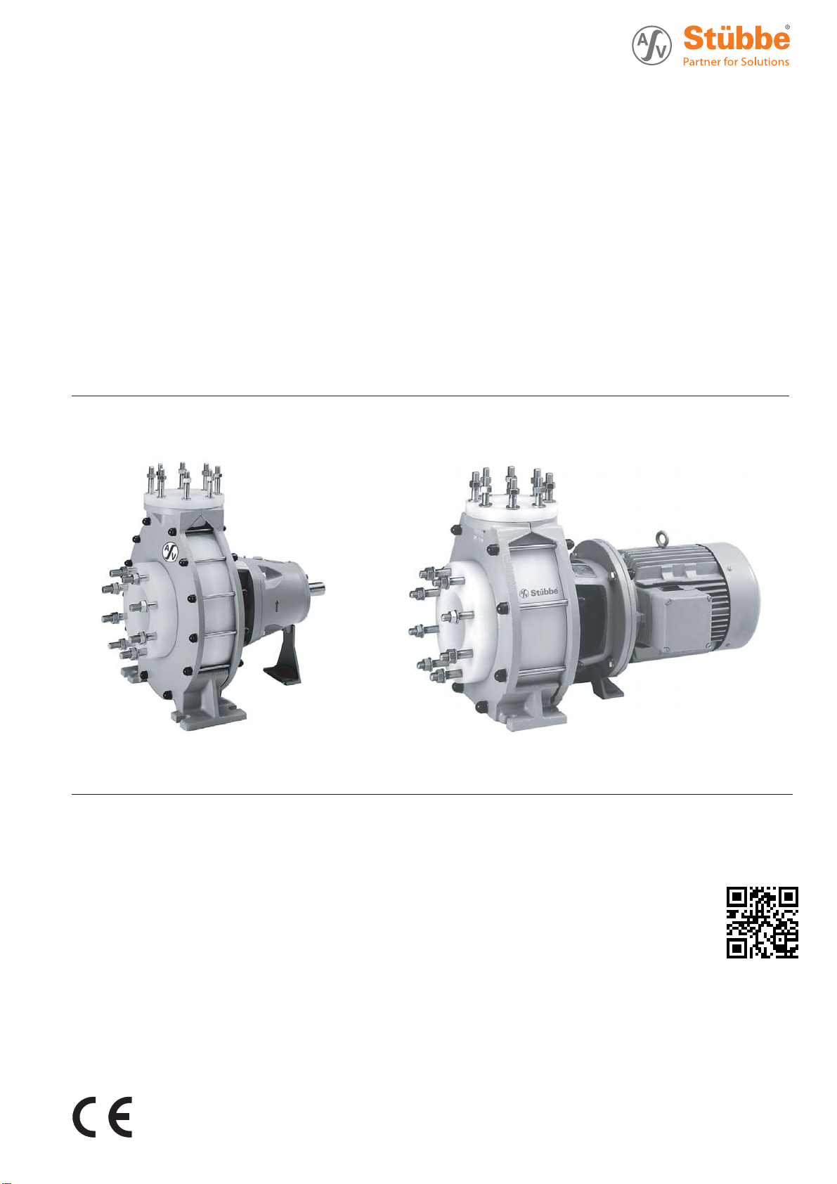
3.2 Description .................................... 9
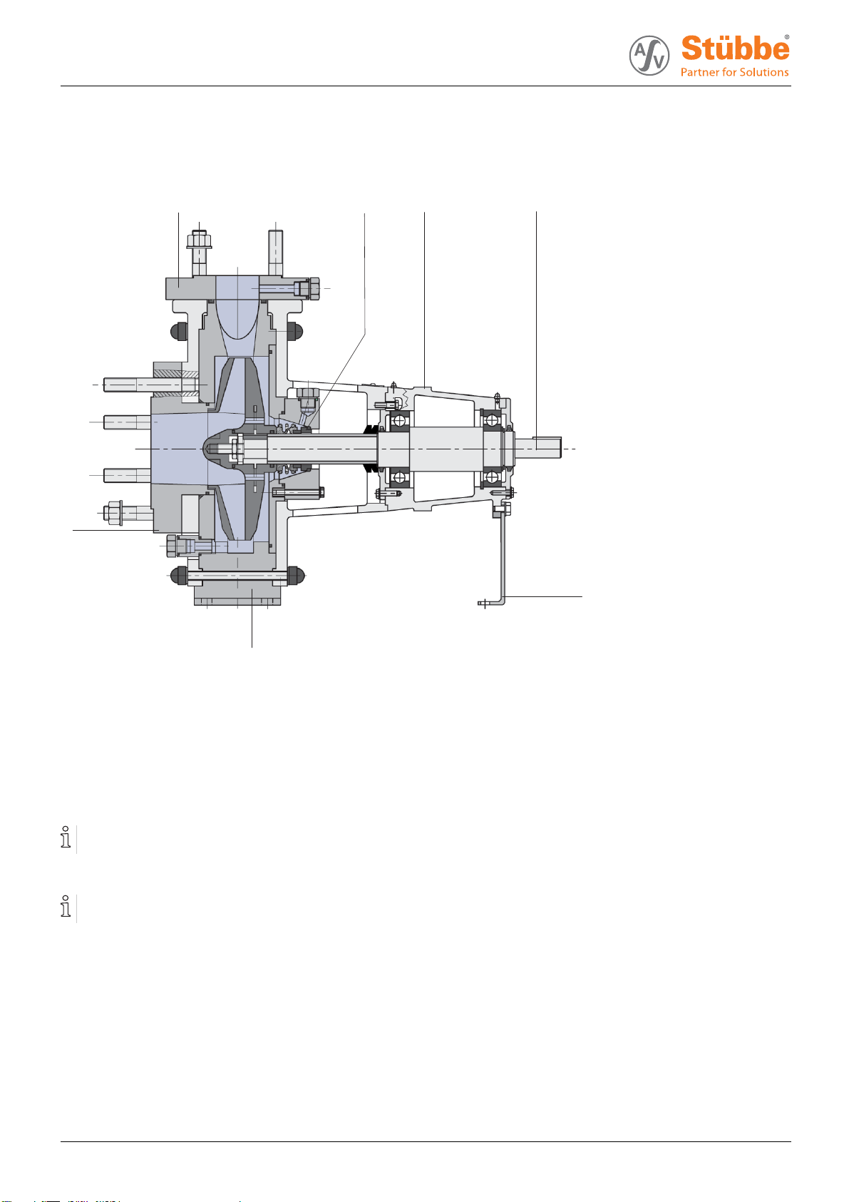
3.3 Layout ......................................... 10
3.4 Shaft seals .................................... 10
3.4.1 Mechanical seals ............................. 10
3.4.2 Auxiliary systems ...... .. . . . . . . . . . . . . . . . . . . . . . 11
4 Transport, Storage and Disposal ................. 12
4.1 Transport ...................................... 12
4.1.1 Unpacking and inspection upon
delivery ........................................ 12
4.1.2 Lifting .......................................... 12
4.2 Storage ....................................... 13
4.3 Disposal ....................................... 13
5 Installation and connection ....................... 14
5.1 Preparing the setup .......................... 14
5.1.1 Check operating conditions ................. 14
5.1.2 Preparing the installation site ............... 14
5.1.3 Prepare foundation and surface ............ 14
5.2 Installing with foundation .................... 15
5.2.1 Place pump unit on the foundation .. . . . . . . . 15
5.2.2 Attaching pump unit .......................... 15
5.3 Installing motor ............................... 16
5.4 Planning the pipes ........................... 16
5.4.1 Specifying supports and flange
connections ................................... 16
5.4.2 Specifying nominal widths ................... 16
5.4.3 Specifying pipe lengths ...................... 17
5.4.4 Provide self-priming container .............. 17
5.4.5 Optimizing changes of cross section and
direction ....................................... 17
5.4.6 Discharging leaks ............................ 17
5.4.7 Providing safety and control devices
(recommended) .............................. 17
5.5 Connecting the pipes ........................ 18
5.5.1 Keeping the piping clean .................... 18
5.5.2 Installing auxiliary pipes ..................... 18
5.5.3 Installing suction pipe ........................ 18
5.5.4 Installing the pressure pipe .................. 18
5.5.5 Inspection for stress-free pipe
connections ................................... 18
5.6 Electrical connection ......................... 18
5.6.1 Connecting the motor ........................ 18
5.6.2 Checking the direction of rotation . . . . ... . . . . 18
5.7 Performing the hydrostatic test .............. 18
5.8 Aligning the coupling precisely .............. 19
5.9 Aligning motor ................................ 19
6Operation............................................ 20
6.1 Preparing for commissioning ................ 20
6.1.1 Checking downtimes ......................... 20
6.1.2 Filling and bleeding .......................... 20
6.1.3 Preparing auxiliary systems (if
present) ....................................... 20
6.1.4 Check direction of rotation ................... 20
6.2 Commissioning ............................... 21
6.2.1 Switching on .................................. 21
6.2.2 Switching off .................................. 21
6.3 Shutting down the pump ..................... 22
6.4 Restoring the pump to service .............. 23
6.5 Operating the stand-by pump ............... 23
7 Maintenance ......................................... 24
7.1 Inspections ................................... 24
7.2 Maintenance .................................. 24
7.2.1 Maintenance in accordance with maintenance
schedule ...................................... 25
7.2.2 Check sealing medium ...................... 25
7.2.3 Cleaning the pump ........................... 25
7.3 Dismounting .................................. 26
7.3.1 Preparations for dismounting ................ 26
7.3.2 Disassembly NM NMB ....................... 27
7.3.3 Disassemble NMXH ......................... 27
7.4 Replacement parts and return .............. 27
7.5 Installing ...................................... 28
7.6 Assembly instruction for shaft protection
sleeve ......................................... 28
8 Troubleshooting .................................... 29
9 Appendix ............................................. 32
9.1 Replacement parts ........................... 32
9.1.1 Series NM .................................... 32
9.1.2 Series NMB ................................... 34
9.1.3 Series NMXH ................................. 36
9.2 Technical specifications ...................... 38
9.2.1 Ambient conditions ........................... 38
9.2.2 Parameters for auxiliary systems ........... 38
9.2.3 Sound pressure level ........................ 38
2 NM NMB NMXH BA-2015.09.18 300 404

Table of contents
9.2.4 Flange tightening torques ................... 38
9.2.5 Tightening torques of casing screws ... . . . . . 38
9.2.6 Gap size ...................................... 38
9.2.7 Lubricant ...................................... 39
9.3 Declaration of conformity in accordance with
EC machinery directive ...................... 40
300 404 BA-2015.09.18 NM NMB NMXH 3

Table of contents
List of figures
Fig. 1 Type plate (example) ........................ 9
Fig. 2 ATEX nameplate (example) ................. 9
Fig. 3 Layout ......................................... 10
Fig. 4 Attach lifting gear to the pump unit .. . . . . . . . 12
Fig. 5 Attach lifting gear to pump ................... 12
Fig. 6 Installation with foundation .................. 15
Fig. 7 Straight pipe lengths in front and after the
pumps (recommended) ...................... 17
Fig. 8 Checking the coupling alignment . ... ... .. .. 19
Fig. 9 Checking for lateral and vertical
misalignment ................................. 19
Fig. 10 Checking angular offset ...................... 19
Fig. 11 Sectional drawing ............................ 33
Fig. 12 Sectional drawing NMB ...................... 35
Fig. 13 Sectional drawing NMXH .................... 37
Fig. 14 Lubricating points with grease nipples . . . . .. 39
List of tables
Tab. 1 Other applicable documents, purpose and
where found .................................. 5
Tab. 2 Warnings and symbols ....................... 6
Tab. 3 Quenching - variants and features .......... 11
Tab. 4 Blocking - variants and features ............ 11
Tab. 5 Measures to be taken if the pump is shut
down .......................................... 22
Tab. 6 Measures depending on the behavior of the
pumped liquid ................................ 22
Tab. 7 Maintenance plan ............................ 25
Tab. 8 Fault/number assignment ................... 29
Tab. 9 Troubleshooting list .......................... 31
Tab. 10 Designation of components according to part
numbers ...................................... 32
Tab. 11 Designation of components according to part
numbers ...................................... 34
Tab. 12 NMXH: Part numbers and component
designations .................................. 36
Tab. 13 Ambient conditions ........................... 38
Tab. 14 Blocking liquid pressure and outlet
temperature ................................... 38
Tab. 15 Flange tightening torques ................... 38
Tab. 16 Tightening torques of casing screws . . . . . . .. 38
Tab. 17 Lubricant ...................................... 39
Tab. 18 Grease/oil lubricant quantity ................. 39
4 NM NMB NMXH BA-2015.09.18 300 404

About this document
1 About this document
This manual
• Is part of the equipment
• Applies to the aforementioned pump series
• Describes safe and appropriate operation during all oper-
ating phases
1.1 Target groups
Operating company
• Responsibilities:
– Always keep this manual accessible where the device
is used on the system.
– Ensure that employees read and observe this docu-
ment, particularly the safety instructions and warnings,
and the documents which also apply.
– Observe any additional country-specific rules and reg-
ulations that relate to the system.
Qualified personnel, fitter
• Mechanics qualification:
– Qualified employees with additional training for fitting
the respective pipework.
• Electrical qualification:
– Qualified electrician
• Transport qualification:
– Qualified transport specialist
• Responsibility:
– Read, observe and follow this manual and the other
applicable documents, especially all safety instructions
and warnings.
1.2 Other applicable documents
Document/purpose/ Where
found
ATEX additional manual (300 364)
• Additional instructions for use in
explosive atmospheres
• http://www.asv-stuebbe.de/
pdf_manuals/300364.pdf
Resistance lists
• Resistance of materials used to
chemicals
• http://www.asv-stuebbe.de/
pdf_resistance/300050.pdf
CE declaration of conformity
• Conformity with standards
(→9.3 De-
claration of
conformity
in accor-
dance with
EC machin-
ery directive,
Page 40).
Data sheet (technical specifications,
operating conditions, dimensions)
NM • Pump NM (340 021)
• http://www.asv-stuebbe.de/
pdf_datasheets/340021.pdf
NMB • Pump NMB (340 022)
• http://www.asv-stuebbe.de/
pdf_datasheets/340022.pdf
NMXH • Pump NMXH (300 416)
• http://www.asv-stuebbe.de/
pdf_datasheets/300416.pdf
Self-
priming
con-
tainer
• Self priming container NM,
NMB, NMXH (300 422)
• http://www.asv-stuebbe.de/
pdf_datasheets/300422.pdf
Supplier documentation
• Technical documentation for supplier
components (e.g mechanical seal)
Documenta-
tion included
Tab. 1 Other applicable documents, purpose
and where found
300 404 BA-2015.09.18 NM NMB NMXH 5

About this document
1.3 Warnings and symbols
Symbol Meaning
• Immediate acute risk
• Death, serious bodily harm
• Potentially acute risk
• Death, serious bodily harm
• Potentially hazardous situation
• Minor injury
• Potentially hazardous situation
• Material damage
Safety warning sign
Take note of all information
highlighted by the safety warning
sign and follow the instructions to
avoid injury or death.
Instruction
1. , 2. , … Multiple-step instructions
Precondition
→Cross-reference
Information, advice
Tab. 2 Warnings and symbols
6 NM NMB NMXH BA-2015.09.18 300 404

General safety instructions
2 General safety instructions
The manufacturer does not accept any liability for any dam-
age caused by disregarding any sections of the entire doc-
umentation.
2.1 Intended use
• Only use the pump with suitable media (→resistance lists).
• Do not use pump with solid particles or abrasive fluids.
If pumps are to be used for solid particles, then agree use
in advance with the manufacturer.
• Do not use pump with combustible or explosive fluids.
• Adhere to the operating limits and size-dependent mini-
mum flow rates.
• Avoid dry running:
Initial damage, such as destruction of bearings, seals and
plastic parts, will occur within a few seconds.
– Make sure the pump is only operated with, and never
without, pumped liquid.
• Avoid cavitation:
– Open suction-side fitting fully and do not use to regulate
flow.
– Do not open the pressure-side fitting beyond the
agreed operating point.
• Avoid overheating:
– Do not operate the pump while the pressure-side fitting
is closed.
–Noteminimumflow (→Data sheet).
• Avoid damage to the motor:
– Do not open the pressure-side fitting beyond the
agreed operating point.
– Note the maximum permissible number of times the
motor can be switched on per hour (→manufacturer's
specifications).
• Consult the manufacturer about any other use of the pump.
• If pumps are delivered without motors, then final assembly
as a pump assembly must take place in accordance with
the provisions of machinery directive 2006/42/EC.
Prevention of obvious misuse (examples)
• Observe pump limits of use regarding temperature, pres-
sure, flow and speed (→Data sheet).
• The power consumption of the pump increases as the the
specific gravity of the pumped fluid increases. Adhere to
the permissible specific gravity in order to eliminate the
possibility that the pump, coupling and motor are over-
loaded (→Data sheet).
A lower specific gravity is permissible. Adapt the auxiliary
systems accordingly.
• When conveying fluids containing solids, observe the limit
values for proportions of solid particles and particle size
(→Data sheet, technical description).
• When using auxiliary plant systems:
– Ensure compatibility of the operating medium with the
product medium.
– Ensure constant supply of the relevant operating
medium.
• Pumps used with water as the pumped liquid must not be
used for foodstuffs or drinking water. Use with food or
drinking water must be specified in the data sheet.
• Typeofinstallationshouldonlybeselectedinaccordance
with these operating instructions. For example, the follow-
ing are not allowed:
– Hanging base plate pumps in the pipe
– Overhead installation
– Installation in the immediate vicinity of extreme heat or
cold sources
– Installation too close to the wall
2.2 General safety instructions
Observe of the following regulations before carrying out
any work.
2.2.1 Product safety
The pump has been built according to state-of-the-art technol-
ogy and the recognized technical safety regulations. Never-
theless, operation of the pump can still put the life and health
of the user or third parties at risk or damage the pump or other
property.
• Only operate the pump if it is in perfect technical condition
and only use it as intended, staying aware of safety and
risks, and in adherence to the instructions in this manual.
• Keep this manual and all other applicable documents com-
plete, legible and accessible to personnel at all times.
• Refrain from any procedures and actions that would pose
a risk to personnel or third parties.
• In the event of any safety-relevant faults, shut down the
pump immediately and have the fault corrected by appro-
priate personnel.
• In addition to the entire documentation for the product,
comply with statutory or other safety and accident-preven-
tion regulations and the applicable standards and guide-
lines in the country where the pump is operated.
300 404 BA-2015.09.18 NM NMB NMXH 7

General safety instructions
2.2.2 Operator's obligations
Safety-conscious operation
• Only operate the pump if it is in perfect technical condition
and only use it as intended, staying aware of safety and
risks, and in adherence to the instructions in this manual.
• Ensure that the following safety aspects are observed and
monitored:
– Adherence to intended use
– Statutory or other safety and accident-prevention reg-
ulations
– Safety regulations governing the handling of haz-
ardous substances
– Applicable standards and guidelines in the country
where the pump is operated
– Applicable guidelines of the operator
• Make personal protective equipment available.
Qualified personnel
• Make sure all personnel tasked with work on the pump
have read and understood this manual and all other appli-
cable documents, especially the safety, maintenance and
repair information, before they start any work.
• Organize responsibilities, areas of competence and the
supervision of personnel.
• Ensure that all work is carried out by specialist technicians
only:
– Fitting, repair and maintenance work
– Transportation
– Work on the electrical system
• Make sure that trainee personnel only work on the pump
under supervision of specialist technicians.
Safety equipment
• Provide the following safety equipment and verify its func-
tionality:
– For hot, cold and moving parts: pump safety guarding
provided by the customer
– For pumps without capability to run dry: Dry run pro-
tection
– For potential electrostatic charging: provide suitable
grounding
Warranty
• Obtain the manufacturer's approval prior to carrying out
any modifications, repairs or alterations during the warranty
period.
• Only use genuine parts or parts that have been approved
by the manufacturer.
2.2.3 Obligations of personnel
• All directions given on the pump must be followed (and kept
legible), e.g. the arrow indicating the sense of rotation and
the markings for fluid connections.
• Pump, coupling guard and components:
– Do not step on them or use as a climbing aid
– Do not use them to support boards, ramps or beams
– Donotusethemasafixing point for winches or sup-
ports
– Do not use them for storing paper or similar materials
– Do not use hot pump or motor components as a heating
point
– Do not de-ice using gas burners or similar tools
• Do not remove the safety guarding for hot, cold or moving
parts during operation.
• Use personal protective equipment if necessary.
• Only carry out work on the pump while it is not running.
• Before all installation and maintenance work, discon-
nect the motor from the mains and secure against being
switched back on again.
• Never reach into the suction or discharge flange.
• Following all work on the pump, refit safety devices in
accordance with the instructions and bring into service.
2.3 Specific hazards
2.3.1 Hazardous pumped liquids
• When handling hazardous fluids, observe the safety regu-
lations for the handling of hazardous substances.
• Use personal protective equipment when carrying out any
work on the pump.
• Collect leaking pumped liquid and residues in a safe man-
ner and dispose of in accordance with environmental reg-
ulations.
2.3.2 Potentially explosive atmospheres
Observe ATEX additional manual
• Additional instructions for use in explosive atmospheres
• www.asv-stuebbe.de/pdf_manuals/300364.pdf
8 NM NMB NMXH BA-2015.09.18 300 404

Layout and function
3 Layout and function
3.1 Labels
3.1.1 Type plate
ASV Stübbe GmbH & Co. KG
Tel.: +49 (0) 57 33 / 79 9-0
Typ
Fabr. Nr.
Werkst.
L ø
Qm3/h Hm
GLRD
1
2
3
4
5
6
7
8
Fig. 1 Type plate (example)
1Pumptype
2 Serial number
3 Housing / sealing material
4–
5 Differential head
6 Shaft seal information
7Flow
8 Impeller diameter [mm]
3.1.2 ATEX nameplate
ASV Stübbe GmbH & Co. KG
Tel.: +49 (0) 57 33 / 79 9-0
Typ
Fabr. Nr.
Werkst.
L ø
Qm3/h Hm
GLRD
1
Fig. 2 ATEX nameplate (example)
1 Explosion protection label
3.2 Description
• NM: Standard pump
– Horizontal, single-stage, non self-priming pump with
single flow volute casing and free shaft end.
– Optionally available complete with coupling and drive
motor, mounted on a base plate.
• NMB: Close coupled pump
– Horizontal, single-stage, non self-priming pump with
single flow volute casing.
–Drivemotorisflanged on to the pump housing with
wafer type flange (without coupling)
– Torque is transmitted from the drive to the pump by an
extended motor shaft.
• NMXH: Standard pump of modular concept
– Horizontal, single-stage, non self-priming pump with
single flow volute casing and free shaft end.
– Slide-in unit can be dismounted without removing
volute casing and piping.
– Optionally available complete with coupling and drive
motor, mounted on a base plate.
300 404 BA-2015.09.18 NM NMB NMXH 9

Layout and function
3.3 Layout
34
5
6
7
12
Fig. 3 Layout
1 Discharge flange
2 Mechanical seal
3 Bearing casing
4Shaft
5 Support foot
6Pumpcasing
7 Suction branch
3.4 Shaft seals
Only one of the following shaft seals can be used.
3.4.1 Mechanical seals
Mechanical seals have a function-related leak.
• Single acting mechanical seal
• Single acting, non-balanced mechanical seal
• Double acting mechanical seal
• Double acting, non-balanced mechanical seal
10 NM NMB NMXH BA-2015.09.18 300 404

Layout and function
3.4.2 Auxiliary systems
Sealing systems
Only one of the following sealing systems can be used.
Quenching
When quenching, the pressure of the pumped medium is
greater than the pressure of the sealing medium. The seal
surfaces are lubricated by the pumped medium.
Examples of use:
• Pumped media which reacts chemically with the air
• Prevention of offensive odors
• Cooling of seals
• Protection from icing
Variant Features of sealing
medium
With open flow • Supplied and drained
continuously
• Unpressurized
In the closed system • Circulating in a closed
circuit
• Unpressurized
Tab. 3 Quenching - variants and features
Blocking
When blocking, the pressure of the sealing medium is greater
than the pressure of the pumped medium. The seal surfaces
arelubricatedbythesealingmedium.
Examples of use:
• Pumped media which crystallizes or contains solids and
therefore damages the seal in the long-term
• Toxic conveyed media
• Environmentally hazardous conveyed media
Variant Features of sealing
medium
With open flow • Supplied and drained
continuously
• Impingedwithpressure
In the closed system • Circulating in a closed
circuit
• Impingedwithpressure
Tab. 4 Blocking - variants and features
300 404 BA-2015.09.18 NM NMB NMXH 11

Transport, Storage and Disposal
4 Transport, Storage and Disposal
4.1 Transport
Weight specifications (→documents for the particular
order).
4.1.1 Unpacking and inspection upon delivery
1. Unpack the pump/pump assembly upon delivery and
inspect it for transport damage.
2. Check completeness and accuracy of delivery.
3. Report any transport damage to the manufacturer immedi-
ately.
4. Dispose of packaging material according to local regula-
tions.
4.1.2 Lifting
DANGER
Death or limbs crushed as a result transported items
falling over.
Use lifting gear appropriate for the total weight to be trans-
ported.
Attach lifting gear in accordance with the following dia-
grams.
Never attach the lifting gear to the lifting eye of the motor
(other than for securing against knocking over for pump
assemblies with a high center of gravity).
Do not stand under suspended loads.
Fig. 4 Attach lifting gear to the pump unit
Fig. 5 Attach lifting gear to pump
1. Attach lifting gear in accordance with the following dia-
grams.
2. Lift pump/pump assembly appropriately.
12 NM NMB NMXH BA-2015.09.18 300 404

Transport, Storage and Disposal
4.2 Storage
NOTE
Material damage due to inappropriate storage!
Store the pump properly.
1. Seal all openings with blind flanges, blind plugs or plastic
covers.
2. Make sure the storage room meets the following condi-
tions:
–Dry
– Frost-free
– Vibration-free
–UVprotected
3. Turnthepumptwiceamonth.
4. Make sure the shaft and bearing change their rotational
position in the process.
4.3 Disposal
Plastic parts can be contaminated by poisonous or radioac-
tive pumped liquids to such an extent that cleaning will be
insufficient.
WARNING
Risk of poisoning and environmental damage by the
pumped liquid or oil!
Use personal protective equipment when carrying out any
work on the pump.
Prior to the disposal of the pump:
– Collect and dispose of any escaping pumped liquid or
oil in accordance with local regulations.
– Neutralize residues of pumped liquid in the pump.
Remove the plastic parts and dispose of them in accor-
dance with local regulations.
Dispose of the pump in accordance with local regulations.
300 404 BA-2015.09.18 NM NMB NMXH 13

Installation and connection
5 Installation and connection
For pumps in potentially explosive atmospheres (→ATEX
additional manual).
NOTE
Material damage due to distortion or passage of electrical
current in the bearing!
Do not make any structural modifications to the pump
assembly or pump casing.
Do not carry out any welding work on the pump assembly
or pump casing.
NOTE
Material damage caused by dirt!
Do not remove the transport seals until immediately before
settingupthepump.
Do not remove any covers or transport and sealing covers
until immediately before connecting the pipes to the pump.
5.1 Preparing the setup
5.1.1 Check operating conditions
Ensure the required operating conditions are met:
– Resistance of body and seal material to the medium
(→resistance lists).
– Required ambient conditions
(→9.2.1 Ambient conditions, Page 38).
5.1.2 Preparing the installation site
Ensure the installation site meets the following conditions:
– Pump is freely accessible from all sides
–Sufficient space for the installation/removal of the pipes
and for maintenance and repair work, especially for the
removal and installation of the pump and the motor
– Pump not exposed to external vibrations (damage to
bearings)
– No corrosive exposure
– Frost protection
5.1.3 Prepare foundation and surface
Aids, tools, materials:
–Steelshims
– Spirit level
Installation options:
– With concrete foundation
– With steel foundation frames
– Without foundation
1. Ensure the foundation and surface meet the following con-
ditions:
– Level and horizontal
– Clean (no oil, dust or other impurities)
– Capable of bearing the weight of the pump assembly
and all operating forces
– Stability of the pump ensured
– With concrete foundation: Normal concrete of strength
class X0 in accordance with DIN EN 206
2. Clean pump sump carefully.
14 NM NMB NMXH BA-2015.09.18 300 404

Installation and connection
5.2 Installing with foundation
NOTE
Material damage due to distortion of base plate.
Position the base plate as follows on the foundation and
attach.
5.2.1 Place pump unit on the foundation
Aids, tools, materials:
– Anchor bolts
– Steel shims
– Mortar casting compound, no shrinkage
– Spirit level
1. Lifting the pump unit (→4.1 Transport, Page 12).
2. Hook anchor bolts in the mounting holes on the base plate
from below.
Observe manufacturers information when using the fixing
material.
3. Position the pump unit on the foundation. When doing so
lower the anchor bolts into the prepared anchoring holes.
32 1 2
Fig. 6 Installation with foundation
4. Align the pump for height and system dimensions using
steel shims as follows:
– Arrange steel shims (2) to the left and right of each
anchor bolt (1).
– If the distance between the anchoring holes is
> 750 mm, then arrange additional steel shims (3) on
each side of the base plate in the center.
5. Ensure that the base plate lies flat against steel shims.
6. Check the permissible height deviation (1 mm/m) using a
mechanical spirit level in a longitudinal and a transverse
direction
7. Repeat the procedure until the base plate is correctly
aligned.
5.2.2 Attaching pump unit
Filling the base plate with mortar casting compound
improves dampening properties.
1. Fill the anchoring holes with mortar casting compound.
2. When the mortar casting compound has set, bolt the base
plate at three points to the specified tightening torque.
3. Before tightening the remaining bolts, arrange shims next
to every bolt to even out any irregularities in the mounting
surface.
300 404 BA-2015.09.18 NM NMB NMXH 15

Installation and connection
5.3 Installing motor
Only necessary if the pump unit is firstassembledonsite.
NOTE
Material damage through bangs and knocks!
Do not tilt the coupling halves when slipping them on.
Do not bang and knock pump components.
1. Smear a very thin coat of molybdenum disulfide (e.g.
Molykote) on the shaft ends of the pump and motor.
2. Insert key.
3. Without mounting rig: Remove rubber buffers and heat
coupling halves to approx. 100 °C.
4. Slideonthepump-sideandmotor-sidecouplinghalves
until the shaft end is flush with the coupling hub. When
doing so, make sure the prescribed distance between the
coupling halves is maintained (→Other applicable docu-
ments, coupling installation instructions).
5. Tighten the threaded pins on both coupling halves.
6. Align the motor shaft end using appropriate shims on the
motor with the height of the pump shaft end.
7. Screw in motor bolts, but do not tighten yet (→5.9 Aligning
motor, Page 19).
5.4 Planning the pipes
Water hammers may damage the pump or the system.
Plan the pipes and fittings as far as possible to prevent
water hammers occurring.
5.4.1 Specifying supports and flange connections
NOTE
Material damage due to excessive forces and torques on
the pump.
Ensure pipes are connected not under tension.
1. Support pipes in front of the pump.
2. Ensure the pipe supports have permanent low-friction
properties and do not seize up due to corrosion.
5.4.2 Specifying nominal widths
Keep the flow resistance in the pipes as low as possible.
1. Ensure nominal suction pipe width is not smaller than the
nominal suction flange width.
–Avoidflow velocities > 2 m/s.
– Recommended flow velocity < 1 m/s
–Maximumflow velocity = 9 m/s
2. Ensure the nominal pressure line width is not smaller than
the nominal pressure flange width.
–Avoidflow velocities in plastic pipes of more than 3 m/s.
– Recommended flow velocity < 3 m/s
–Maximumflow velocity = 12 m/s
– Install a vent valve, check valve and pressure gauge in
pressure line just behind the discharge flange.
16 NM NMB NMXH BA-2015.09.18 300 404

Installation and connection
5.4.3 Specifying pipe lengths
C
D
B
A
Fig. 7 Straight pipe lengths in front and after the
pumps (recommended)
A>5xDNs
BDNs
CDNd
D>5xDNd
Observe recommended minimum values when installing
the pump.
Suction side: Shorter lengths are possible, but may limit
hydraulic performance data.
Pressure side: Shorter lengths are possible, but may result
in increased noise development.
5.4.4 Provide self-priming container
Aself-primingcontainercanbeusedtomakethepump
self-priming.
1. Select container volumes according to the size of the
pump.
2. Clean containers carefully prior to commissioning or initial
filling.
5.4.5 Optimizing changes of cross section and
direction
1. Avoid radii of curvature of less than 1.5 times the nominal
pipe diameter.
2. Avoid abrupt changes of cross-section along the piping.
5.4.6 Discharging leaks
WARNING
Risk of injury and poisoning due to hazardous pumped
liquids!
Safely collect any leaking pumped liquid, then discharge
and dispose of it in accordance with environmental regula-
tions.
1. Provide equipment for collecting and discharging leaking
liquids.
2. Ensure the free discharge of leaking liquids.
5.4.7 Providing safety and control devices
(recommended)
Avoid contamination
1. Install filters in the suction pipe.
2. Install a differential pressure gauge with contact manome-
ter to monitor contamination.
Avoid reverse running
1. Ensure that the medium does not flow back after switch-
ingoffthepumpbyusinganon-returnvalvebetweendis-
charge flange and stop valve.
2. In order to enable venting, include vent connection
between discharge flanges and non-return valve.
Make provisions for isolating and shutting off the pipes
For maintenance and repair work.
Provide shut-off devices in the suction pipe and pressure
line.
Allow measurements of the operating conditions
1. Provide pressure gauge in the suction pipe and pressure
line for pressure measurement.
2. Provide motorside load monitors (over and underload).
3. Provide pressure measurement on the pump side.
Providing dry run protection
In order to protect the pump from dry running and resulting
damage
– Provide dry run protection
– e.g. ASV PTM pressure and temperature monitoring
sensor
Provide an overpressure protection
Overpressure protection is required for operation in explo-
sive areas (→ATEX additional manual).
Provide an overpressure protection.
300 404 BA-2015.09.18 NM NMB NMXH 17

Installation and connection
5.5 Connecting the pipes
NOTE
Material damage due to excessive forces and torques on
the pump.
Ensure pipe connection without tension.
5.5.1 Keeping the piping clean
NOTE
Material damage due to impurities in the pump!
Make sure no impurities can enter the pump.
1. Clean all piping parts and fittings prior to assembly.
2. Flush all pipes carefully with neutral medium.
3. Ensure no flange seals protrude inwards.
4. Remove any blind flanges, plugs, protective foils and/or
protective paint from the flanges.
5.5.2 Installing auxiliary pipes
Observe manufacturer information for any auxiliary sys-
tems present.
1. Connect the auxiliary pipes to the auxiliary connections so
that they are stress-free and do not leak.
2. Avoid formation of air pockets: Run the pipes with a con-
tinuous slope up to the pump.
5.5.3 Installing suction pipe
1. Remove the transport and sealing covers from the pump.
2. Fit suction pipe stress-free and sealed. (→9.2.4 Flange
tightening torques, Page 38).
3. Ensure no seals protrude inwards.
4. For the suction process: Install foot valve in the suction
pipe in order to prevent the pump and suction pipe from
dry running when pump is not running.
5.5.4 Installing the pressure pipe
1. Remove the transport and sealing covers from the pump.
2. Fit pressure line stress-free and sealed. (→9.2.4 Flange
tightening torques, Page 38).
3. Ensure no seals protrude inwards.
5.5.5 Inspection for stress-free pipe connections
Piping installed and cooled down
1. Disconnect the pipe connecting flanges from the pump.
2. Check whether the pipes can be moved freely in all direc-
tions within the expected range of expansion:
– Nominal width < 150 mm: by hand
– Nominal width > 150 mm: with a small lever
3. Make sure the flange surfaces are parallel.
4. Reconnect the pipe connecting flanges to the pump.
5. If present, check support foot for tension.
5.6 Electrical connection
DANGER
Risk of death due to electric shock!
All electrical work must be carried out by qualified electri-
cians only.
Before all work on the electrical system, disconnect the
motor from the mains and secure against being switched
back on again.
5.6.1 Connecting the motor
Follow the instructions of the motor manufacturer.
1. Connect the motor according to the connection diagram.
2. Make sure no danger arises due to electric power.
3. Install an EMERGENCY STOP switch.
5.6.2 Checking the direction of rotation
Only possible when starting up (→6.2 Commissioning,
Page 21).
5.7 Performing the hydrostatic test
Only necessary if the entire system needs to be tested
under pressure.
NOTE
Material damage due to bursting of pump casing.
Testing pressure must not exceed the permissible pump
pressure (→documents for the particular order).
Make sure the testing pressure does not exceed the per-
missible pump pressure.
– If necessary, do not perform pressure test on the pump.
18 NM NMB NMXH BA-2015.09.18 300 404

Installation and connection
5.8 Aligning the coupling precisely
Only necessary for versions with coupling.
DANGER
Danger to life from rotating parts.
For all installation and maintenance work, disconnect the
motor from the mains and secure against being switched
back on again.
NOTE
Material damage due to incorrect alignment of coupling.
Align the motor exactly to the pump if there is any vertical,
lateral or angular misalignment.
For more detailed information and for special couplings:
(→Manufacturer information).
Checking the coupling alignment
Aids, tools, materials:
– Feeler gauge
– Straight edge
– Dial gauge (possibly for couplings with spacer piece)
– Other appropriate tools, e.g. laser alignment device
1
2
A
Fig. 8 Checking the coupling alignment
1. Measure the coupling in two planes on the circumference
at an angle of 90°.
2. Check the light gap on the outer circumference with straight
edge (1):
– Lay straight edge across both coupling halves.
– Align the motor if there is a visible gap on the outer
circumference (→5.9 Aligning motor, Page 19).
3. Check the gap size with feeler gauge (2):
– Permitted gap dimension (→9.2.6 Gap size,
Page 38).
– Measure size of the gap between the coupling halves
using feeler gauge (A).
– If the gap size is not permitted, align the motor
(→5.9 Aligning motor, Page 19).
Fig. 9 Checking for lateral and vertical misalignment
4. Check for any lateral or vertical misalignment using the dial
gauge:
– Complete measurement as shown.
– Align the motor if there is any lateral or vertical mis-
alignment (→5.9 Aligning motor, Page 19).
Permissible axial or radial deviation, measured on cou-
pling front or circumference: < 0.05 mm
Fig. 10 Checking angular offset
5. Checking for angular displacement
– Complete measurement as shown.
– If there is any angular displacement: align the motor.
Permissible angular offset < 0.03 mm
5.9 Aligning motor
1. Align the motor so that the coupling halves align exactly, if
necessary place alignment plates underneath.
2. Check alignment.
3. Repeat alignment procedure if there is still a vertical mis-
alignment.
4. After that, tighten the motor bolts.
300 404 BA-2015.09.18 NM NMB NMXH 19

Operation
6Operation
For pumps in potentially explosive atmospheres (→ATEX
additional manual)
6.1 Preparing for commissioning
6.1.1 Checking downtimes
Check downtimes (→6.4 Restoring the pump to service,
Page 23).
6.1.2 Filling and bleeding
WARNING
Risk of injury and poisoning due to hazardous fluid!
Use protective equipment for any work on the pump.
Safely collect the fluid and dispose of it in accordance with
environmental regulations.
NOTE
Material damage as a result of dry running
Make sure the pump is filled properly.
1. If present, fill and vent self-priming container with fluid.
2. Open the suction-side fitting.
3. Open the pressure-side fitting.
4. Fill pump and suction pipe with fluid.
5. Verify that no pipe connections are leaking.
6.1.3 Preparing auxiliary systems (if present)
The manufacturer accepts no liability for damage aris-
ing due to the installation or use of a third party or
non-approved auxiliary system.
Sealing systems
1. Ensure that the sealing medium is appropriate to mix with
the pumped medium.
2. Ascertain the sealing system
(→documents for the particular order)
3. Install the sealing system (→manufacturer information).
4. Ensure the necessary parameters for the sealing system
(→manufacturer information).
5. Ensure that the container pressure is not lower than that
permitted for blocking pressure systems (→manufacturer
information).
6.1.4 Check direction of rotation
DANGER
Danger to life from rotating parts.
Use personal protective equipment when carrying out any
work on the pump.
Maintain an adequate distance from rotating parts.
NOTE
Material damage as a result of dry running.
Make sure the pump is filled properly.
1. Switch on motor for max. of 2 seconds and switch off again
immediately.
2. Check whether the sense of rotation of the motor matches
the direction of rotation on the fan.
3. If the sense of rotation is different: change over the two
phases (→5.6 Electrical connection, Page 18).
20 NM NMB NMXH BA-2015.09.18 300 404
This manual suits for next models
2
Table of contents
Other Stübbe Water Pump manuals