Rolair CHINOOK User manual

UNPACKING INSTRUCTIONS
Your compressor was inspected at the factory and packaged to protect against shipping
damage. Inspect your unit for damage or missing parts. If any damage occurs or parts are
missing as a result of shipping, a notation to that effect should be made on the Delivery
Receipt. Claims should be settled directly with the transportation company.
LUBRICATION
Prior to initial start-up, fill the crankcase to the designated level with a single viscosity, non-
detergent oil. The oil sight gauge should be filled up to ¾ full. You should be able to see a
small bubble at the top of the sight gauge. Be sure not to fill above the indicated level. DO
NOT USE A DETERGENT OIL! All models are splash lubricated by means of dippers on the
connecting rods. The pump must be operated in a level position for proper lubrication.
BELTS
Install belts on compressor and motor pulleys. Belt tension should be adjusted to allow 3/8”
to ½” deflection with normal thumb pressure.
DRIVE PULLEYS
Drive pulleys must be properly aligned and belt drive tension set to specifications. Improper
pulley alignment and belt tension can cause motor overloading, excessive vibration and
premature belt and/or bearing failure. As the compressor starts, check the rotation of the
flywheel. The direction of the rotation must be counter-clockwise when facing the flywheel.
Should the rotation be incorrect, disengage the power supply and check the motor wiring.
*SPECIAL NOTE: Compressor flywheel has left-hand thread. Remove nut by turning
clockwise.
To determine the correct motor pulley, use the formula below:
Motor Pulley = Flywheel O.D. x Compressor RPM
Motor RPM
GUARDS
Guards should be designed to achieve the required degree of protection and still allow full air
flow from the compressor sheave across the unit. When the compressor is installed, make
sure the guard side is at least 18” away from a wall to provide adequate cooling of the motor
and pump. DO NOT RUN COMPRESSOR WITHOUT BELT GUARD INSTALLED!

OIL CAPACITY
Pump Model # Oz’s. of Oil Pump Model # Oz’s. of Oil
PMP11K3 6 PMP22K25 61
PMP11K8 12 PMP22K28 48
PMP12K11 17 PMP22K30 47
PMP12K12 15 PMP22K35 48
PMP12K17 34 PMP22K50 59
PMP12K18 34 PMP24K60 98
PMP22K22 61 PMP24K100 127
PMP22K24 61
MAINTENANCE
Regular maintenance insures trouble-free operation. Your new compressor represents the
finest engineering and construction available. However, even the finest machinery requires
periodic maintenance. A good maintenance program will add years of service to your air
compressor. The following is recommended as a minimum maintenance program. For your
protection, disconnect power supply after each day’s operation and drain air from system
before any maintenance.
BREAK-IN PERIOD
Your new pump does not come filled with oil. By using the chart below, select the type of oil
that best fits your application:
TEMPERATURE 0° - 32° 32° - 55° 56° & ABOVE
NON-DETERGENT OIL 10 WT 20 WT 30 WT
IMPORTANT: Replace the oil after the first 50 hours (2 weeks) of operation. Re-torque the
head bolts after the first 200 hours (4 weeks) of operation.
MAINTENANCE SCHEDULE
DAILY 1. Check oil level and fill as needed.
EVERY 2 WEEKS OR 100 HOURS 1. Repeat daily procedure.
2. Replace oil after first 50 hours of operation.
3. Check drive belt and adjust if necessary.
MONTHLY OR 200 HOURS 1. Repeat above procedures.
2. Change compressor oil.
3. Check for air and oil leaks and correct.
4. Tighten all hardware.
ANNUALLY OR 2000 HOURS 1. Repeat monthly procedures.
2. Check the valves in the compressor and
replace if damaged or worn.

TROUBLESHOOTING & SOLUTIONS
PROBLEM POSSIBLE CAUSE CORRECTIVE ACTION
Knocking 1. Lack of oil in crankcase
2. Worn piston pin
3. Worn main bearings
4. Worn connecting rod
5. Excessive crankshaft end play
6. Dirty or defective check valve
7. Piston hitting head due to foreign
matter or carbon deposits.
1. Add oil
2. Replace pin
3. Replace bearings
4. Replace inserts or rod assembly
5. Take to Service Center
6. Clean or replace
7. Inspect, repair or replace valves &
pistons
Overheating
Compressor
1. Poor ventilation
2. Dirty cooling surfaces
3. Dirty or defective check valve
4. Restricted air intake
5. Low oil level
6. Unit not run on level surface
7. Dirty or defective reed valve
1. Move compressor to allow for
better ventilation
2. Clean compressor pump
3. Clean or replace
4. Replace filter
5. Add non-detergent, single viscosity
oil
6. Level unit
7. Clean valve plate and replace valves
Low Discharge
Pressure or
Pumps Slowly
1. Air leaks
2. Broken or dirty valves
3. Restricted air intake
4. Blown gaskets
5. Defective gauges
6. Dirty or defective check valve
7. Compressor too small for application
1. Check system for air leaks.
2. Replace or clean valves & valve
plates
3. Replace filter element
4. Replace gaskets
5. Replace gauges
6. Clean or replace check valve
7. Consult dealer for larger ROLAIR
compressor
Compressor
Fails to Attain
Proper RPM’s
1. Defective check valve
2. Defective pilot valve
1. Repair or replace check valve
2. Repair or replace pilot valve
Oil in the
Discharge Air
1. Worn piston rings
2. Compressor air intake restricted
3. Restricted crankcase breather
4. Excessive oil in basic compressor
pump
5. Wrong oil viscosity
1. Replace rings
2. Replace filter
3. Clean crankcase breather
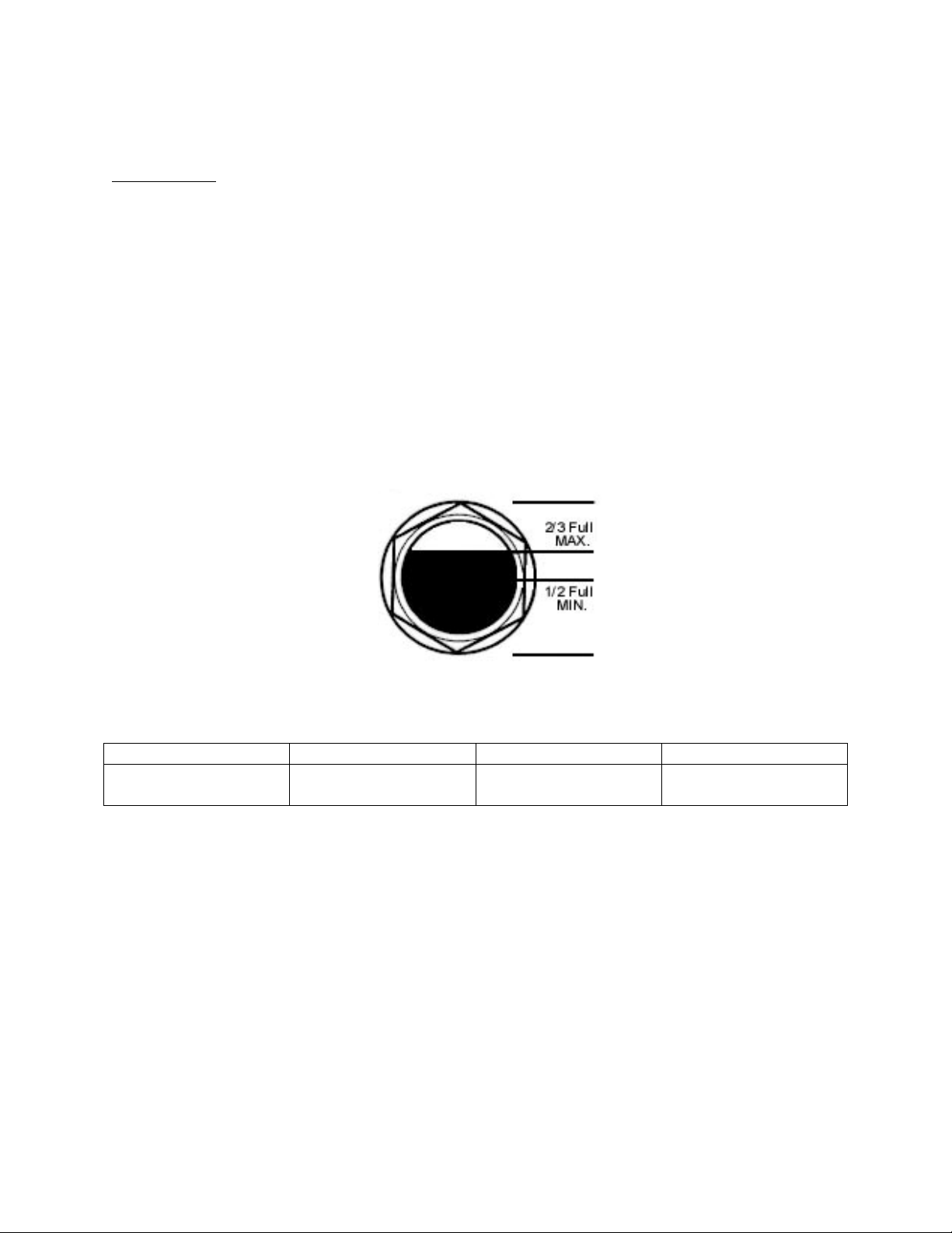
4. Check gauge and adjust to proper
oil level
5. Drain & replace with non-detergent
single viscosity oil
Excessive Oil
Consumption
1. Restricted or dirty air filter
2. Crankcase is over-filled with oil
3. Valves not seating properly
4. Worn piston rings
1. Clean or replace air filter
2. Drain oil & refill to proper oil level
3. Clean crankcase breather
4. See ROLAIR Service Center
Water in
Crankcase
1. Compressor does not run long
enough to get hot and vaporize the
moisture
2. Compressor too large for application
3. Incorrect or inferior grade of oil
1. Consult dealer about smaller ROLAIR
compressor
2. Consult ROLAIR dealer
3. Change oil in compressor

AIR COMPRESSOR OPERATION
LUBRICATION
Prior to daily operation, make a habit of checking the oil level in your compressor pump. A
sight gauge on the outside of the pump’s crankcase is provided to make the job easier.
Always maintain the oil level to read 2/3 full on the sight gauge. Oil levels over this amount
will result in oil blowing past the rings or through the crankcase breather. Lower amounts of
oil will result in insufficient lubrication of moving parts.
Reciprocating compressors will consume a certain amount of oil under normal operation. If
you are concerned about your oil consumption, monitor and record oil consumption daily and
consult your local dealer. When filling your crankcase with oil, be sure to use a single
viscosity, non-detergent oil. DO NOT USE A DETERGENT OIL!!
OIL SIGHT GAUGE
Oil Type Table
Temperature 0° - 32° 33° - 55° 56° & Above
Non-detergent
Straight Weight 10 WT 20 WT 30 WT
IMPORTANT
Unit must be level when in operation.
Table of contents
Other Rolair Water Pump manuals
Popular Water Pump manuals by other brands

Grundfos
Grundfos JP Booster PS Series Installation and operating instructions

Pentair
Pentair Hydromatic SKV50 Installation and service manual

Graco
Graco CHECK-MATE 200 instruction manual

Intex
Intex FastFill AP619DA owner's manual

Zoeller
Zoeller 4290 installation instructions

Samson
Samson KL Series Directions for use