Section 5
SUGGESTED INSTALLATION
The pipe size should be at least the size of the inlet and
discharge ports of the pump or larger if highly viscous
material is being pumped.The suction hose must be non-
collapsible, reinforced type as the SANIFLO™ VC pump is
capable of pulling a vacuum. It is critical that all fittings
and connections are airtight or a reduction or loss of
pump suction capability will result.
INSTALLATION: Months of careful planning, study
and selection efforts can result in unsatisfactory pump
performance if installation details are left to chance.
Premature failure and long term dissatisfaction can be
avoided if reasonable care is exercised throughout the
installation process.
LOCATION: Noise, safety and other logistical factors
usually dictate where equipment should be situated on
the production floor. Multiple installations with conflicting
requirements can result in congestion of utility areas,
leaving few choices for additional pumps.
Within the framework of these and other existing
conditions, every pump should be located in such a way
that six key factors are balanced against each other to
maximum advantage.
ACCESS: First, the location should be accessible. If it
is easy to reach the pump, maintenance personnel will
have an easier time carrying out routine inspections and
adjustments. Should major repairs become necessary,
ease of access can play a key role in speeding the repair
process and reducing total downtime. Verify that the site
also allows for ease of cleaning and proper drainage
during wash down.
AIR SUPPLY: The HPVC pump is furnished with a one-
half inch (NPT) ball valve as the point of connection for
compressed air. Although air consumption varies with
each application/installation of the HPVC pump; the air
supply should be sized to provide at least 32 CFM @ 75
PSI. Furnished with your pump are an air filter and two
regulatorfilter combinations equipped with automatic
drains. The regulator marked “suction” controls the
amount of pressure available to the vacuum generator.
This pressure should be set at no more than 75 PSI to
ensure maximum efficiency.
The regulator marked “discharge” controls the amount of
pressure used to discharge the product from the pump.
The proper amount of discharge pressure is determined
by several factors including pumping distance, required
flow rate, product viscosity and piping size.
ELECTRICAL : The control panel requires 120/220VAC at
.1 amps.
ELEVATION: Selecting a site that is well within the pump’s
dynamic lift capability will assure that loss-of-prime
troubles will be eliminated. In addition, pump efficiency
can be adversely effected if proper attention is not given
to site location.
PIPING: Final determination of pump site should not be
made until the piping problems of each possible location
have been evaluated. The impact of current installations
should be considered ahead of time to make sure that
inadvertent restrictions are not created for any remaining
sites.
The best choice possible will be a site involving the
shortest and straightest hook-up of suction and discharge
piping. Unnecessary elbows, bends and fittings should
be avoided. Pipe sizes should be selected to keep friction
losses within practical limits. All piping should be
supported independently of the pump. In addition, the
piping should be aligned to avoid placing stresses on the
pump fittings.
If the pump is to be bolted down to a solid location, a
mounting pad placed between the pump stand and the
foundation will assist in minimizing pump vibration.
The proper orientation for this SANIFLO™ VC pump is to
have the vertical column in the vertical position.
SOLIDS PASSAGE CAPABILITIES:
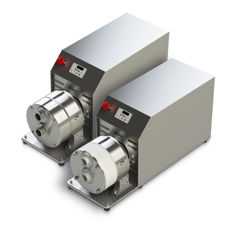
CONNECTING PUMP TO CONTROL PANEL: The control
panel should be connected to the pump as close as
possible without putting the control panel in harms way.
The control panel comes complete with seven feet of hose
to connect the control panel to the pump.The control panel
may be mounted farther from the pump than seven feet,
but this will decrease the capacity of the pump slightly.
Moving the control panel farther away will also increase
the air consumption by approximately five-percent for
every additional ten feet of air tubing. The sanitary cap
which houses the probe and diffuser screen is placed on
top of the vertical tube and secured by a four inch sanitary
clamp.Your pump is now connected to the control panel.
CONNECTING PUMP TO HOPPER: The correct way to
connect the hopper to the pump is from the bottom of
the hopper using sanitary pipe & fittings. NOTE: When
connecting pump to any type of hopper, never place the
flex hose into the hopper from the topside. The hopper
should always be connected to the pump from the bottom
of the hopper.
VC4 7.6 cm (3")
VC6 10.2 cm (4")
VC8 15.2 cm (6")
5WILDEN PUMP & ENGINEERING CO., LLC
WIL-12120-E-01


