Dowell PIEZOART User manual

USER MANUAL

CONTENTS
- INTRODUCTION
- USER GUIDELINES
- PRODUCT FEATURES & ADVANTAGES
- PRODUCT COMPONENTS
- PART NAME FOR CONTROL BOX
- BUTTONS ON THE OPERATION PANEL
- LCD WINDOW
- BUTTONS ON THE FOOT CONTROLLER
- CONNECTION OF EACH PART
- OPERATION PROCESS
- MAINTENANCE OF THE PRODUCT
- ATTENTION
- PRODUCT SPECIFICATION
- ELECTROMAGNETIC COMPATIBILITY INFORMATION
- WARRANTY
- SYMBOL

INTRODUCTION
This product is a medical device.
Please make sure to read this manual before using.
This manual is to assure proper installation and usage.
Pay attention when reading the manual in order to properly use this product and to assure prolonged
lifespan of the product. Specifically, pay attention to the contents with marks such as , and .
<User>
•Qualified Professional
<Intended use>
•This is a device that uses ultrasonic piezoelectric technology for surgery.
<Classification of equipment>
•Type of protection against electric shock: Class I equipment
- To avoid the risk of electric shock, this equipment must be connected to the main electrical supply and
is properly grounded.
•Degree of protection against electric shock: Type BF applied part
•Classification according to the degree of protection against ingress of water as detailed in the current edition of IEC 60529:
- Control Box: IPX0
- Foot Controller: IPX8
•Not suitable product to use where there exists flammable anesthetic mixture with air or with oxygen.
•User sterile product (non-sterile product at shipment)
•Classification according to mode of operation: Intermittent operation
•Applied parts: Ultrasonic Tip
<Use time>
•Loading time: 1 minutes
•Resting time: 10 minutes
<Operation & Storage condition>
Operating condition
Transport and storage condition
Temperature (℃)
Relative humidity (%R.H.)
Atmospheric pressure (hPa)
Temperature (℃)
Relative humidity (%R.H.)
Atmospheric pressure (hPa)
10~35
10~80
700~1,060
-20~60
10~90
500~1,060
Type BF
2

3
● Please pay attention when using to consider the patient’s safety most importantly.
● Check the condition of the product before use.
● Stop using and inspect the product when an abnormal sign occurs such as calescence, vibration or noise before
or during operation.
● Please contact manufacturer if problem cannot be solved.
● For safety, prepare extra consumables before using.
● Please sterilize and lubricate the piezo handpiece right after use. Otherwise, it could be damaged due to
coagulation of blood inside the product.
● The control box and foot ontroller are not steam cleaning or sterilization part.
● The input power is available at AC 100-120V.
(Check input voltage before connecting the AC power.)
● Dispose the irrigation tube as a medical waste after use.
● Contact manufacturer if an incorrect display appears on the screen.
● Do not drop or mishandle the product.
● Do not damage the irrigation tube, as it will not work properly when the tube is broken or dislodges.
● The product is designed to be used indoors; do not use outdoors.
● Do not use the product in a humid or dusty environment.
● Use only regulated products and consumables by the manufacturer. Otherwise, there could be a risk of an accident or failure.
● Replace the cords immediately when it is worn-out or damaged to prevent electric shock to the user or patient.
● Manufacturer may change specification and design of this product in order to improve the quality.
● User has responsibility to operate and maintain this product.
●
This product is not Sterilized by manufacturer or distributor. Please make sure to sterilize before operating. (User sterilization)
● US Federal law restricts this device to only to a dentist.
● Do not sterilize with different methods other than moist heat sterilization. It may cause damage to the product
USER GUIDELINES
CAUTION
● Do not drop or damage the piezo handpiece. In case of malfunctioning, , dropping or falling in water,
do not use it and contact the manufacturer.
● Do not damage or drop the LCD part of the control box.
● The product needs special precautions regarding EMC (Electromagnetic Compatibility)
● Portable and mobile Radio Frequency communications equipment can affect the product.
Do not use Radio Frequency equipment near for the product.
● The system may present a possibility of malfunction when used in the presence of an electromagnetic
interference wave. Do not install the system in the vicinity of the device which emits magnetic waves.
Turn off the power switch of the Control box when an ultrasonic oscillation device or an electrode knife
is located in the vicinity where is its used.
● For safety, install the control box in a place where the power cord can be easily removed.
(It is possible to disconnect the control box from the power source by removing the power cord.)
WARNING

● Do not use a damaged or broken power cord, plug, or outlet. It may cause fire and/or electric shock.
● When unplugging the power cord, do not touch cord with wet hand.
● Do not use loose power cord, it could cause electric shock and fire.
● Do not damage the power cord (do not bend too hard, or put heavy objects on it).
That may cause electric shock and/or fire.
● Unauthorized modification and dismantling is prohibited.
● Do not use a solvent such as thinner or benzene for cleaning.
※ Please use an absorbent and alcohol to wipe the controller box. Do not wipe with wet cloth.
※ Be careful not to drop liquid on control box.
● Do not place the product near any heated equipment and do not put candles or cigarettes on it.
● Use only a grounded outlet. Please contact electrical technician or manufacturer regarding the ground connection.
● The product must be used by specialist or dentist. If not, patient might get hurt from improper use.
● If patient is taking antibiotics, patient needs to consult with doctor before operation.
● Keep product away from spray containing flammable material.
● Manufacturer does not have any responsibility for defects or loss to property in the following cases:
1. User did not follow the instruction manual when using the product.
2. Used the product in a place of unregulated wire condition.
3. Unauthorized person repaired the product.
4. Did not follow the instruction manual for this product.
● Do not use on the following patients.
1. Those with medical complications or allergies
2. Those who have pre-existing conditions (E.g. Cardiac, Pulmonary, Renal disturbance or High blood pressure)
3. Those who are pregnant or lactating
4. Patients with cardiac pacemakers and infants
PROHIBITED
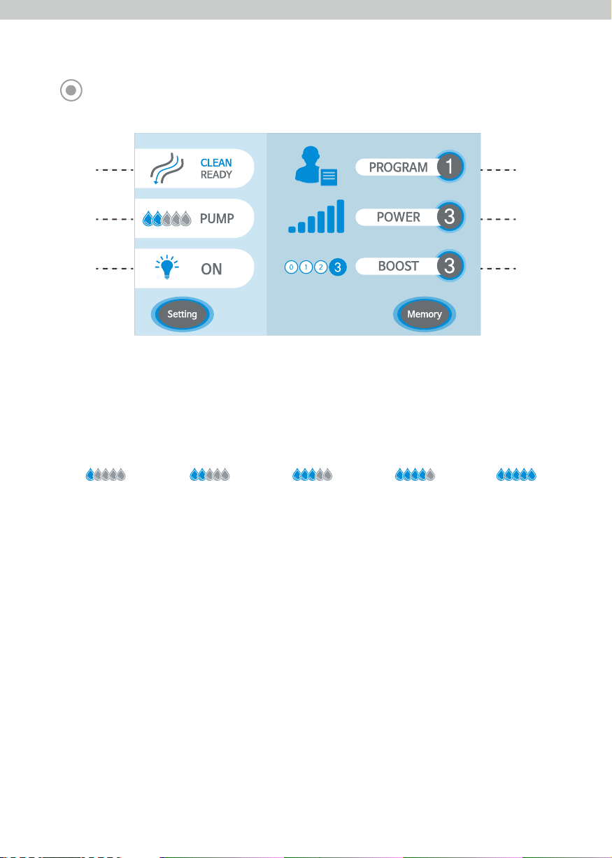
<Ultrasonic Surgery Functions>
- Users can set up Power and Boost selections in order to have the best settings for each individual.
- Power: Level 1, 2, 3
- Boost: Level 0, 1, 2, 3
<Program Memory Function>
- 3 programmable memories for setting Power, Boost, Irrigation Pump, Optic.
(There are total 5 programs and program no. 4 and no. 5 have certain settings for ultrasonic tips so they have separate
Power and Boost setting.)
<Clean/Ready Function>
- It cleans out the air in the irrigation tube to produce consistent flow before and after surgery.
<Ergonomic Foot Controller>
- The ergonomically designed Foot Controller with key functions can be used during surgery for user’s convenience.
<Optic Function>
- LED light from piezo handpiece helps to see clearly during any surgery.
(It only operates on the piezo handpiece with an optic function.)
PRODUCT FEATURES & ADVANTAGES
4

5
* Please check all components are included. (Some components may be changed by the manufacture.)
PRODUCT COMPONENTS
- Saline Solution Pack is not included in a set.
- Irrigation tube is disposable. Do not reuse.
No. No.
Control Box
Piezo Handpiece
Foot Controller
Handpiece Stand
Hanger
Irrigation Tube
※ Listing Number : D289551
Tube Holder
1
2
3
4
5
6
7
8
9
10
11
12
13
Torque wrench
Tip Holder
Sterilization Case
Power Cord
Instruction Manual
Ultrasonic Tip
※ Listing Number : D250061
Component Component
①
②
③
④
⑤
⑥
⑦
⑧
⑨
⑩
⑪
⑫
⑬

6
PART NAME OF CONTROL BOX
Hanger Hole
Irrigation Pump
Piezo Handpiece Connector
LCD Display
Foot Controller Connector
Main Power Switch
Fuse Box
Main Power Socket

BUTTONS ON THE OPERATION PANEL
Clean/Ready
Button
Pump Button
Optic Button
Setting Button
Program Button
Power Button
Boost Button
Memory Button
It cleans out the air in the irrigation tube and creates consistent flow before and after surgery.
(Only irrigation pump will operate when you press Clean/Ready Button.
Handpiece will not operate)
Use for setting the irrigation volume, It is possible to set the level from 1 to 5.
This is Optic light selection button. This option only applied to piezo handpiece
with optic function.
It can control volume and reset unit’s settings.
- Volume Control: Manages volume from level 0 to 3
- Reset: Resets all of system settings.
It will return to primary menu once you press the button one more time.
Program selection is from 1 to 5.
Output power setting for piezo handpiece can be from level1 to 3.
Ultrasonic tip’s frequency setting from level 0 to 3 for adequate surgery environment.
Memorizes current program settings to selected number.
Level 1 (35 ㎖/min ±25%)
Level 2 (50 ㎖/min ±25%)
Level 3 (70㎖/min ±20%)
Level 4 (90 ㎖/min ±20%)
Level 5 (110 ㎖/min ±20%)
7

LCD WINDOW
①
②
③
④
⑤
⑥
1. CLEAN/READY Display
: Clean/Ready icon will be flashing when Clean/Ready is operating.
2. Irrigation Volume Display
: Shows current irrigation volume display. The irrigation volume goes from level 1 to 5.
It is displayed with water drops icons to show volume being used.
3. Optic Display
: : When the bulb sign is on, it shows the Optic function is operating.
* This function only operates a on piezo handpiece with optic function.
* Optic function will operate once the foot controller is pushed.
4. Program Number Display
: It shows current programs that user is in. Program options are from 1 to 5.
5. Power Display
: Output power setting from piezo handpiece can be set from level1 to 3.
6. Boost Display
: Ultrasonic tip’s frequency setting is from level 0 to 3 for an adequate surgery environment.
Level 1 Level 2 Level 3 Level 4 Level 5
8

BUTTONS ON THE FOOT CONTROLLER
1. Program Button
: This button can change the program. It will go up in numbers of program when you press and if you would
like to go down, then press longer than 3 seconds.
(Program will not go down consecutively so press the button for longer than 3 second again.)
2. Foot pedal
: It operates the piezo handpiece by pushing the pedal.
3. Irrigation Pump Button
: It adjusts the irrigation pump volume and the volume will go up when you press it. It will reset to level 1
when you press it longer than 3 seconds.
4. No Function
③④
①
②
9

CONNECTION OF EACH PART
1. Piezo Handpiece Connection
: Insert the piezo handpiece connector. Check if the holes and pins of motor connector are lined-up.
2. Foot Controller Connection
: Insert the foot controller connector. Check if the holes and pins of foot controller connector are lined-up.
Then screw the connector and lock.
3. Power Cord Connection
: Insert the power cord into the power socket in the back of the control box.
- When connecting the piezo handpiece, foot controller and power cord,
please make sure the power is off.
(Otherwise, it might cause a malfunction.)
③① ②④
⑤
connector lock.
10

4. Irrigation Tube Connection
Open the irrigation pump cover upwards.
Close the irrigation pump cover downwards.
Make sure that the irrigation pump cover is
completely closed.
Place the irrigation tube in the center
part of the irrigation pump correctly.
Place the irrigation tube part in the edge of
irrigation pump as shown in the image with
arrows. Otherwise, saline will not flow properly.
Confirm with this image whenthe irrigation
pump cover with irrigation tube is closed.
- When not in use for for a long period of time, open the irrigation pump cover.
Irrigation tube might change its shape and cause a malfunction.
Saline connection
handpiece connection
AB
B-1 C
D
C-1
11

5. Hanger Placement
: Put the hanger into the hanger hole on the top side of the control box.
6. Irrigation Tube Insertion
: Insert the irrigation tube needle into the bag and place with the bag downward.
Close the irrigation tube stopper and then insert the breather needle.
7. Irrigation Nozzle Connection
: Insert the irrigation tube to the irrigation pump pipe placed in the end of piezo handpiece like
the image below.
- If the pump is in operation mode but water does not come out of the handpiece,
the irrigation tube may be broken or damaged.
Irrigation tube needle
lrrigation Stopper
lrrigation tube
Tube holder connection
Put the piezo handpiece cord and irrigation tube together
with the tube holders. Insert the tube holder to the piezo
handpiece cord and then insert the irrigation tube in order
to create a better working condition.
Piezo handpiece cord
Tube holder
breather needle
8. Ultrasonic Tip Connection
(1) Screw the ultrasonic tip carefully to clockwise.
(2) Use the torque wrench to tighten the ultrasonic tip.
12

OPERATION PROCESS
■ Before Operation
1. Turn on the main switch.
- Wait until the image below shows up on the screen.
- Replace the ultrasonic tip immediately when it is broken, bent, or worn out. If it is not replaced,
it may cause an injury or less efficiency during the surgery.
- Ultrasonic tips may break when you use tips that are not compatible or when it is used excessively.
- Before any surgery, install the ultrasonic tip and use the Clean/Ready function to check
if the irrigation pump is working correctly.
- By pressing button or foot controller will lead to the next screen.
2. Place the piezo handpiece where it can test spraying then push the button in order to remove
air inside of the irrigation tube.
2. Operate a surgery by pressing foot pedal from foot controller.
■ Post –Operation
1. Clean the product.
Refer to the instruction manual’s ‘Maintenance of the Product’.
2. Use torque wrench to disassemble the ultrasonic tip by rotating to counter-clockwise.
3. Sterilize the product.
Refer to the instruction manual’s ‘Maintenance of the Product’.
4. Keep the product in a hygienic place.
- It is most convenient to save programs to program settings for easier operation.
- Please use methods below to save program settings.
- When the ultrasonic tip touches an object before it runs, it may cause an error.
Please run ultrasonic tips first then start surgical procedure.
■ During Operation
1. Adjust personal settings with the , , buttons for individual surgeries.
* Please refer the piezo tip reference guide for the manufacturer's setting recommendations.
13

■ Program Storage
1. Press the button to select user’s preferred program.
2. Finalize the setting by selecting the modes from the , , , buttons.
3. Press the button to save the settings.
■ SETTING
1) Volume Control
■ Error and Remedy
: The following error codes are for those errors or issues that may lead the handpiece to stop.
Press the button to select the menu.
Press the button to increase the volume.
Press the button to decrease the volume.
button or button will lead to the main screen after saving the setting.
Press the button to select the menu.
Press the button to accept.
Press the button to deny.
Once user selected YES button, it will reset the setting.
If No button is selected, it will advance to the main menu.
Press the button to go back to main menu.
CauseError Remedy
Foot Controller became damaged.
Piezo Handpiece cord is not connected properly.
Piezo Handpiece became damaged.
Ultrasonic tip is not installed.
Ultrasonic tip is running by touching an object.
Ultrasonic tip is broken.
Ultrasonic tip is not tightened properly.
Foot Controller cord is not connected properly.
Please contact the manufacturer.
Reconnect the Piezo Handpiece cord properly.
If the error doesn’t get solved out, contact the manufacturer or dealer.
Please contact the manufacturer.
Install the ultrasonic tip.
Run the ultrasonic tip first then use for surgery.
Replace the ultrasonic tip.
Use the torque wrench to tighten the ultrasonic tip precisely.
Press the Foot Pedal once. If the error message does not disappear,
contact the manufacturer or dealer.
Reconnect the Foot Controller cord properly.
If the error message does not disappear,
contact the manufacturer or dealer.
E1
E2
E3
* In Programs 1~3, POWER and BOOST values are adjustable. Please refer to the setting values as described on "Tip Manual"
* Programs 4~5 have "FIXED" POWER and BOOST values and these are NOT adjustable.
Programs 4-5 are available to use for all Saeshin Piezo tips.
- Program 4 is for exclusive use of SP-020i
- Program 5 is for exclusive use of SP-028i
- When using a normal tip in Program 4~5, the power increases, but the tip may break.
2) Reset
14

Check the fuse if the control box doesn’t work. If necessary contact your dealer.
Fuse Box
MAINTENANCE OF THE PRODUCT
■ Fuse Change
■ Cleaning
■ Sterilization
Sterilization Temperature Time Dry Time
Moist heat sterilization(pre-vacuum) 132℃ 4 minutes 30 minutes
1. Piezo Handpiece
① Wipe the surface of piezo handpiece with with an alcohol swab or a paper towel after removing the dirt.
② Visually inspect the handpiece in a bright area after cleaning. If there are any foreign substances left, repeat first step.
- Be careful that the water does not come into the piezo handpiece.
- After use, detach the irrigation tube from the saline solution pouch connected the irrigation pump and
then push the Clean/Ready button to remove the saline solution remaining inside the handpiece.
2. Ultrasonic Tip
① Place the piezo handpiece in a good drainage location in order to empty out the irrigation line and the used ultrasonic tip.
② Irrigation pump will operate when you press Clean/Ready button on the operation panel and the icon will appear on the display.
③ Keep pressing the Clean/Ready button to clean for at least 35 seconds.
④ Use the Torque Wrench to separate the ultrasonic from the piezo handpiece.
⑤ Remove any contaminants using a nylon brush after soaking for 3 minutes in Enzymatic Detergent.
⑥ Rinse using tap water for 3 minutes to remove Enzymatic Detergent of from ultrasonic tip.
⑦ Perform an ultrasonic wash for 10 minutes using the Enzymatic Detergent at 35℃ ~ 45℃.
⑧ Perform the Ultrasonic rinsing 3 times for 3 minutes using purified water at 35℃ ~ 45℃. (However, replace purified water every time.)
⑨ Wipe using dust-absorbent cloth after the ultrasonic tip soaked in alcohol (70%) for 30 seconds.
⑩ Please visually inspect the ultrasonic tip in a bright area after cleaning.
If the ultrasonic tip is still soiled after cleaning, the cleaning process must be repeated.
- Proteolytic enzyme detergents are recommended as an Enzymatic Detergent.
- It is recommended to use ethanol for alcohol (70%).
- If the device is determined not to be visually clean at the end of the cleaning step, the user should either repeat
the previous cleaning steps or safely dispose of the device, so the visibly soiled device is not used again.
3. Torque Wrench
① Please remove the cleaned ultrasonic tip with the torque wrench.
② Before the remaining blood has dried, wipe the torque wrench with an alcohol swab after use
Sterilization Product List
· Piezo Handpiece
· Ultrasonic Tip
· Torque Wrench
Sterilization Method
① Dry the applicable parts completely after cleaning.
② Place the ultrasonic tip back in the tip holder.
③ Place the tip holder with ultrasonic tips inside, piezo handpiece and torque wrench into sterilizing case and close the cover.
④ Put the sterilization case in a sterilizer unit and run for 4 minutes at 132 ℃, and let dry for 30 minutes.
⑤ To maintain the sterilization status, keep the sterilized products in a sterilized pouch (or wrap) approved by the FDA.
- Maximum sterilization number of piezo handpiece is 250 times.
- Do not sterilize with different methods other than moist heat sterilization. It may cause damage to the product.
- Make sure to dry the applicable products before sterilization.
- Do not soak the piezo handpiece into any liquid. Ultrasonic resonator can be damaged.
- Piezo handpiece and cord cannot be disassembled.
- Irrigation tube is disposable. Do not re-use.
- Do not wet the connector and controller unit’s socket.
- After the sterilization, dry the product completely.
132
15

ATTENTION
1. Please read the notice below before operating the product.
① Check the connection of all cords and correct operation when powering-on.
② Check if the ground connection is safe.
③ Make sure to check any contact part to patient.
④ Check the voltage.
⑤ Check the sterile condition of any autoclavable parts.
2. Please read the notice below during the product use.
① Constantly check the status of the product and patient during surgery.
② When product or patient has any problem, stop the operation for the patient’s safety and take the proper action.
③ Do not let patient approach or touch the product.
3. Please read the notice below after operating the product.
① Do not put any physical pressure on the all cords.
4. When the products are not being used for a long period, please be advised to the followings.
① Clean out the irrigation areas.
② Turn off the power and unplug the cord. Check the cord regularly and replaceit if it becomes damaged.
③ Clean and sterilize.
PRODUCT SPECIFICATION
1. Control Box
2. Piezo Handpiece
3. Foot Controller
Model Name
Frequency of
piezo operation
PEZ10LN
27 ± 3KHz
Model Name
Classification according to the degree
of protection against ingress of water
(IEC 60529)
FUS10
IPX8
Model Name
Rated voltage
Fuse
Rated Frequency
Power Consumption
Output of
piezo operation
Max. Irrigation Volume
PIEZOART
AC 100-120 V
5 A
50 / 60 Hz
48 VA
15~59 VA
Max. 110㎖/min ± 20%
16

ELECTROMAGNETIC COMPATIBILITY INFORMATION
In IEC/EN 60601-1-2 4th edition. These limits are designed to provide reasonable protection against harmful
interference in a typical medical installation. This equipment generates, use and can radiate radio frequency
energy and, if not installed and used in accordance with the instructions, may cause harmful interference
to other devices in the vicinity. However, there is no guarantee that interference will not occur in a particular
installation. If this equipment does cause harmful interference to other devices, which can be determined
by turning the equipment off and on, the user is encouraged to try to correct the interference by one
or more of the following measures:
- Reorient or relocate the receiving device.
- Increase the separation between the equipment.
- Connect the equipment into an outlet on a circuit different from that to which the other device(s) are connected.
- Consult with the dealer.
Electromagnetic Emissions
The PIEZOART is intended for use in the electromagnetic environment specified below.
The customer or the user of the PIEZOART should assure that it is used in such an environment.
Emission test Compliance Electromagnetic environment - guide
RF emission – CISPR 11
EN 55011 Group 1
PIEZOART
uses RF energy for internal operation.
Therefore, its radiofrequency emissions are very low and
are not likely to cause any interference in nearby equipment.
RF emission – CISPR 11
EN 55011 Class A
Harmonic emission –
IEC 61000-3-2
EN 61000-3-2
Class A
Voltage fluctuations
Flicker emission –
IEC 61000-3-3
EN 61000-3-3
Compliance
PIEZOART
covers devices for usage in all establishments
other than domestic and that are not directly connected to
a low voltage power supply network, which supplies
domestic environment.
This is a class A product. In a domestic environment this
product may cause radio interference in which case the
user may be required to take adequate measures.
17

Electromagnetic Immunity
The PIEZOART is intended for use in the electromagnetic environment specified below. The customer
or the user of the PIEZOART should assure that it is used in such an environment.
Emission test IEC 60601
test level Compliance level Electromagnetic environment – guidance
Electrostatic discharge (ESD)
IEC 61000-4-2
EN 61000-4-2
±8kV contact
±15kV air
Floors should be wood, concrete or ceramic tile.
If floors are covered with synthetic material,
the relative humidity should be at least 30%.
Electrical fast transients
IEC 61000-4-4
EN 61000-4-4
±2kV for power
supply lines ±1kV
for input/output lines
Surges
IEC 61000-4-5
EN 61000-4-5
±1kV differential
mode ±2kV
common mode
Voltage dips,
short interruptions and
voltage variations
IEC 61000-4-11
EN 61000-4-11
0 % UT for 0.5 cycle
at 8 Φ angles
0% UT for 1 cycle
70 % UT for 25/30 cycles
0 % UT for 250/300 cycle
±8kV contact
±15kV air
±2kV for power
supply lines ±1kV for
input/output lines
±1kV differential
mode ±2kV
common mode
0 % UT for 0.5 cycle
at 8 Φ angles
0% UT for 1 cycle
70 % UT for 25/30 cycles
0 % UT for 250/300 cycle
Power mains quality should be that of a typical
commercial or hospital environment.
Power mains quality should be that of a typical
commercial or hospital environment.
Power mains quality should be that of a typical
commercial or hospital environment. If the user
requires continued operation during power mains
interruptions, it is recommended that
the PIEZOART get power from an uninterruptible
power supply or battery.
Power frequency (50/60Hz)
magnetic field
IEC 61000-4-8
EN 61000-4-8
NOTE: UT is the a.c. mains voltage prior to application of the test level.
30 A/m 30 A/m
Power frequency magnetic fields should be at levels
characteristic of a typical location in a typical
commercial or hospital environment.
18

Electromagnetic Immunity
The PIEZOART is intended for use in the electromagnetic environment specified below. The customer or the user of
the PIEZOART should assure that is used in such an environment.
Immunity test IEC 60601
test level Compliance level Electromagnetic environment – guidance
Conducted RF
IEC 61000-4-6
EN 61000-4-6
3 Vrms
150 kHz to 80 MHz
6 Vrms
In ISM bands from
150 kHz to 80 MHz
Portable and mobile RF communications equipment
should be used no closer to any part of the
PIEZOART
including cables, than the recommended separation
distance calculated from the equation applicable to
the frequency of the transmitter.
Radiated RF
IEC 61000-4-3
EN 61000-4-3
3 V/m
80 MHz to 2.7 GHz
Note 1: At 80 MHz and 800 MHz, the higher frequency range applies.
Note 2: These specifications may not be applicable in all situations. Electromagnetic propagation is affected by absorption and reflection from structures,
objects and persons.
(a): The electromagnetic field strength of fixed radiofrequency emitters, such as base stations for mobile telephones (cellular / cordless), mobile radio,
AM/FM radio broadcasts and TV broadcasts cannot be determined exactly by theory.
To assess the electromagnetic environment due to fixed radiofrequency emitters, an electromagnetic environment measurement must be made.
If the measured radiofrequency field strength in the immediate environment where the product is used exceeds the compliance level specified above,
the performance of the product must be tested to verify whether it conforms to the specification. If abnormal performance is observed, additional
measures may be necessary, such as reorienting or relocating the product.
(b): In the 150 kHz to 80 MHz frequency range, the electromagnetic field strengths must be less than 3V/m.
3 Vrms
150 kHz to 80 MHz
6 Vrms
In ISM bands from
150 kHz to 80 MHz
3 V/m
80 MHz to 2.7 GHz
Recommended separation distance
d = 1.2 √P
d = 1.2 √P 80MHz to 800MHz
d = 2.3 √P 800MHz to 2.7GHz
Where ‘P’ is the maximum output power rating of the transmitter in watt (W)
according to the transmitter manufacturer
‘d’ is the recommended separation distance (m).
The electromagnetic field strength of fixed radiofrequency emitters, which is
determined by an electromagnetic environment measurement (a), must be
less than the compliance level in each frequency range (b).
Interference may occur near equipment marked with the symbol below:
19
This manual suits for next models
1
Table of contents
Other Dowell Dental Equipment manuals
Popular Dental Equipment manuals by other brands

Komet
Komet ER C-Post Series Instructions for use

KaVo Dental
KaVo Dental MULTIflex LUX coupling Midwest instructions

Castellini
Castellini SKEMA 6 Series manual

KaVo
KaVo SMARTair plus Instructions for use

DCI Edge
DCI Edge ORTHODONTIC CHAIR installation instructions

Pelton & Crane
Pelton & Crane Spirit 1800 Series installation instructions