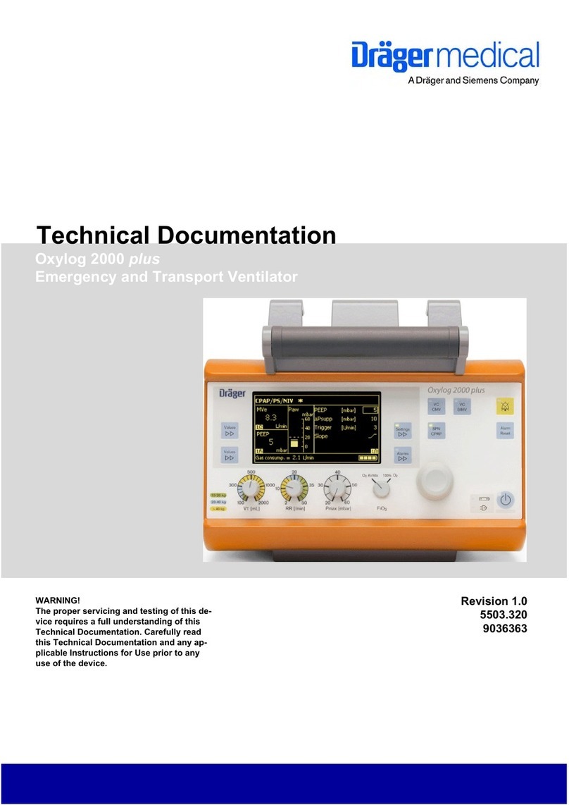
Dräger Medical Savina User manual

5664.900
9036060
Revision 8.0
Because you care
Emergency Care • Perioperative Care • Critical Care • Perinatal Care • Home Care
Technical Documentation
Savina
Intensive Care Ventilator


All rights reserved. Copyright reserved.
ENK5664900IECIVZ.fm 04.01.06
I
Contents
General
1Notes 3
1.1 Symbols and Definitions ......................................................................................................... 4
Function Description
1General 7
1.1 Working principle .................................................................................................................... 7
1.2 Monitoring ............................................................................................................................... 7
2Principal components 9
2.1 Electronics ............................................................................................................................ 10
2.2 Control panel ........................................................................................................................ 14
2.3 Pneumatics ........................................................................................................................... 17

All rights reserved. Copyright reserved.
ENK5664900IECIVZ.fm 04.01.06
II
Contents
Maintenance Procedures
1General notes 25
2Replacing the microfilter 25
3Replacing the dust filter set 27
4Replacing the O2 sensors 28
5Replacing the filter in the O2 inlet 29
6Replacing the lead-gel battery (internal battery) 34
Schematics and Diagrams
1Front view, Savina 41
2Rear view, Savina 43
3Identification of PCBs 46
3.1 O2 Valve PCB .......................................................................................................................46
3.2 Control PCB ..........................................................................................................................48
3.3 Front Panel PCB ...................................................................................................................49
3.4 O2 Diaphragm PCB ..............................................................................................................50

All rights reserved. Copyright reserved.
ENK5664900IECIVZ.fm 04.01.06
III
Contents
4Pneumatic diagrams 52
5Tubing diagram 54
Annex
Parts catalog
Test List
Technical Information

All rights reserved. Copyright reserved.
ENK5664900IECIVZ.fm 04.01.06
IV
Contents

1
General

2

5664.900
Observe protection mark DIN 34. Copyright reserved.
Version 2.0_ Released_Printed on_04.01.06_K5664900_General.fm
3
Savina General
1Notes This Technical Documentation conforms to the IEC 60601-1 standard.
Read each step in every procedure thoroughly before beginning any test.
Always use the proper tools and specified test equipment. If you deviate from
the instructions and/or recommendations in this Technical Documentation,
the equipment may operate improperly or unsafely, or the equipment could
be damaged.
Use only original Dräger parts and supplies.
The maintenance procedures described in this Technical Documentation may
be performed by qualified service personnel only. These maintenance
procedures do not replace inspections and servicing by the manufacturer.
The information in this manual is confidential and may not be disclosed to
third parties without the prior written consent of the manufacturer.
Strictly follow the Instructions for Use manual / Operating
Instructions! This Technical Documentation does not replace the
Instructions for Use manual / Operating Instructions. Any use of the
product requires full understanding and strict observation of the
product-specific Instructions for Use manual/ Operating Instructions.
Reference is hereby made to the observance of the relevant safety
provisions, for example in Germany, the Medical Product Law (MPG), the
Medical Device Operator Ordinance (MPBetreibV), the Pressure Container
Ordinance (Druckbehälterverordnung), the Technical Rules for Pressurized
Gases (Technische Regeln Druckgase), or the Occupational Health and
Safety Provisions (Unfallverhütungsvorschriften).
Unless otherwise stated, reference is made to laws, regulations or
standards (as amended) applicable in the Federal Republic of Germany.
Follow the laws and regulations applicable in your country.

Observe protection mark DIN 34. Copyright reserved.
Version 2.0_ Released_Printed on_04.01.06_K5664900_General.fm
45664.900
General Savina
1.1 Symbols and
Definitions
This symbol indicates a warning.
This symbol indicates tips and useful information.
This symbol is used to alert against unsafe practices when handling
electrostatic sensitive devices (ESD).
Definitions according to German standard DIN 31051:
Inspection = examination of actual condition
Maintenance = measures to maintain specified condition
Repair = measures to restore specified condition
Servicing = inspection, maintenance, and repair

5
Function Description

6

5664.900
For internal use only. Copyright reserved.
Version 3.0_ Released_Printed on_04.01.06_F5664900T01IEC.fm
7
Savina Function Description
1 General Savina is a long-term ventilator unit designed for patients with a tidal volume
of 50 mL and above, and for the following applications:
– Intensive care unit
– Recovery room,
– Secondary transportation from hospital to hospital,
– Patient transfer within the hospital,
– Transfer flights.
1.1 Working principle Savina generates the compressed air for ventilation with a blower, which
means Savina is able to ventilate without any connection of compressed air
or oxygen. A controllable valve is switched in parallel with the blower to regu-
late the pre-set ventilation parameters. The valve opens or closes according
to the pre-set ventilation parameters.
To increase the oxygen concentration in the ventilatory gas, an oxygen con-
centrator, such as Permox SilentCare, can be connected. If compressed oxy-
gen is connected to Savina, the oxygen concentration of the ventilating gas
can be precisely metered. The oxygen concentration is then metered inter-
nally with sensors, the associated electronics, and a bank of valves.
1.2 Monitoring Savina has the following monitoring system:
Measured values Additional information
Measurement of the airway pressure
(Paw)
Pressure curve is pT1-filtered. (T1 =
100 ms)
The bargraph is additionally
smoothed.
Measurement of insp. and exp. flow ---
Measurement of peak flow (Flow-
Peak)
---
Measurement of the inspiratory O2
concentration (FiO2)
PT1-filtered T1 = 2 s
Measurement of airway peak pres-
sure (Ppeak)
---
Measurement of plateau pressure
(Pplat)
---
Measurement of airway mean pres-
sure (Pmean)
---.
Measurement of the positive end-
expiratory pressure (PEEP)
---
Measurement of the expiratory vol-
ume (Vte)
Using the phase information from
the ventilation control, the measured
value is determined over one man-
datory breath.
Measurement of the expiratory
minute volume (MV)
Determined over 1 minute and fil-
tered.
Measurement of the spontaneous
minute volume (MVspon)
Determined over 1 minute and fil-
tered.

For internal use only. Copyright reserved.
Version 3.0_ Released_Printed on_04.01.06_F5664900T01IEC.fm
85664.900
Function Description Savina
Measurement of the total frequency
(Ftot)
Determined over 1 minute and fil-
tered.
Measurement of the spontaneous
frequency (Fspn)
Determined over 1 minute and fil-
tered.
Measurement of the inspiratory-expi-
ratory ratio (I:E).
Using the phase information from
the ventilation control, the inspiratory
time Tinsp and the expiratory time
Texp of one respiratory cycle are
determined. They are used to calcu-
late I:E = Tinsp/Texp. The measured
I:E-ratio is available as output value
until the next inspiration is com-
pleted.
A measurement is not carried out
when an ASB breath changes into to
a mandatory breath.
The output values become invalid
when the measurement is inactive,
when a new value has not been
determined for 15 s, or when more
than 45 s have elapsed since the
start of inspiration.
Measurement of the plateau time
(Tplat)
Measurement of the inspiratory time
(Tinsp)
Using the phase information from
the ventilation control, the inspiratory
time Tinsp and the plateau tiem
Tplat are determined. The measured
times are available as output values
until the next inspiration is com-
pleted.
A measurement is not carried out
when an ASB breath changes into to
a mandatory breath.
The output values become invalid
when the measurement is inactive or
when no new values have been
determined for 15 seconds.
Measurement of the airway resis-
tance (R)
---
Measurement of the compliance (C) ---
Measurement of the temperature at
the Y-piece (Temp.)
---
Only if optional NIV is enabled

5664.900
For internal use only. Copyright reserved.
Version 3.0_ Released_Printed on_04.01.06_F5664900T01IEC.fm
9
Savina Function Description
2 Principal compo-
nents
Savina consists of the electronics, the operator control unit and the pneu-
matic system, containing the following principal components:
Leakage volume in percent (MVleak) The patient flow and the patient flow
clamped towards zero are totalized
in two flow totalizers and their aver-
age is determined over 400 ms.
These average values are filtered
using a Bessel filter of the fourth
order each and are then used as val-
ues for the leakage volume MVleak
and the inspiratory minute volume
MVinsp.
This results in the MVleak readout
according to:
MVleak [%] = 100% * MVleak /
MVinsp.
Patient volume (VTpat) ---
Alarm limits / monitoring
Apnea detection is adjustable (monitoring can be switched off in NIV).
Detection of dead space-intensive spontaneous breathing (tachypnea mon-
itoring).
Airway pressure monitoring adjustable.
Monitoring of minimum and maximum minute volumes is adjustable.
Monitoring of maximum tidal volume is adjustable (monitoring can be
switched off in NIV).
The minimum and maximum limits for FiO2 are adjustable in (optional) LPO
mode.
A disconnection time, by which the “!!! Airway pressure low” warning is
additionally delayed, is only adjustable in NIV.
Electronics Control panel Pneumatics
Power pack Front Panel PCB Plug-in unit
Control PCB Display Valve block
Motor Commutation
PCB
Membrane keypad Inspiratory block
O2 Valve PCB Control knob Pressure measuring
unit
O2 Diaphragm PCB Patient system
Fan Flow sensors

For internal use only. Copyright reserved.
Version 3.0_ Released_Printed on_04.01.06_F5664900T01IEC.fm
10 5664.900
Function Description Savina
2.1 Electronics
Figure 1 Block diagram of the electronics with operator control
2.1.1 Power pack The power pack delivers the supply voltages for Savina. The input voltage
range of the power pack is 100 V to 240 V AC and 50 Hz to 60 Hz. However,
the power pack can also be operated with an external rechargeable battery
(12 V or 24 V) or with an external on-board - ambulance/helicopter - power
supply (10.5 V to 36 V).
The connection for the alternating voltage is made by a power cable. The
connection for the external rechargeable battery or the external on-board
power supply is made by a coded plug.
The power pack actuates the three “Mains power”, “External battery or on-
board power supply” and “Internal battery” LEDs. The LEDs are mounted on
the membrane keypad of the operator control, and indicate the current oper-
ating status.

5664.900
For internal use only. Copyright reserved.
Version 3.0_ Released_Printed on_04.01.06_F5664900T01IEC.fm
11
Savina Function Description
Savina includes 2 internal rechargeable batteries (2 x 12 V) which enable
uninterrupted operation in the event of a complete failure of external power.
The internal rechargeable batteries supply the O2 sensors with power, even
when the Savina is switched off. As a result, valid O2 values are available
immediately on power-up.
The power pack supplies the following output voltages:
–+5V
– -15 V
–+15V
–+24V
–+48V
The output voltages are short-circuit-proof and stable at no-load.
The output voltages are generated according to the following priority, depen-
dent on the input voltages:
The fan cools the power pack. The heated air removes excess oxygen from
the control unit and warms the patient system.
2.1.2 Control PCB The Control PCB is the central “control and monitoring unit” of the Savina. It
includes two separate processor systems: the master and front processors.
The program memories are Flash-EPROMs. The Flash-EPROMs can be pro-
grammed with a laptop connected to the serial port of the Savina (software
download).
An EEPROM is provided for each processor system for storage of change-
able, non-volatile data. The EEPROM of the master stores the calibration
data of the sensors, fan, etc. The EEPROM of the front processor stores
safety parameters, settings such as contrast, sound volume, etc., as well as a
“backup copy” of the operating hours. The EEPROM of the front processor is
plugged in and, if the board needs to be replaced, must be mounted on the
new board.
The board is provided with a real-time clock which is used to display the time
and to store the software options, the unit identification and the operating
hours. The real-time clock is buffered by a battery which is integrated in the
real-time clock. The real-time clock also holds the logbook. The real-time
clock is plugged in and, if the board needs to be replaced, must be mounted
on the new board.
Input voltage Priority Action
AC voltage 1 Charge external and internal batteries, and maintain the charge.
External on-board
power supply
2 Charge internal batteries, and maintain the charge.
External battery/batter-
ies
3 Charge internal batteries, and maintain the charge.
Internal batteries 4 -

For internal use only. Copyright reserved.
Version 3.0_ Released_Printed on_04.01.06_F5664900T01IEC.fm
12 5664.900
Function Description Savina
The control PCB contains the following functions:
– Processing of the signals from the sensors (O2, flow, pressure, tempera-
ture),
– Control of the blower and valves
– Monitoring of the unit functions and the supply voltages
– Actuation of the displays
– Keypad interpretation
– Delivery of the internal and external interfaces.
Figure 2 Block diagram: Control PCB
2.1.3 Motor Commutation PCB The motor commutation PCB controls the motor of the blower. The entire
control functionality is located in a self-contained housing. The supply voltage
is +48 V, and is delivered by the power pack. The +48V on the Motor Com-
mutation PCB are protected with a fuse (6.3AT).
The input voltage range of the Motor Commutation PCB is 12 to 52.5V. The
rotation speed is set by the Control PCB. The control voltage for the rotation
speed is 0 to +5.00 V, corresponding to a rotation speed of 0 to 12,000 rpm.
The rotation speed range is 4000 to 12.000 rpm.

5664.900
For internal use only. Copyright reserved.
Version 3.0_ Released_Printed on_04.01.06_F5664900T01IEC.fm
13
Savina Function Description
The Motor Commutation PCB delivers the “actual rotation speed signal” to
the Control PCB. The “actual value signal” is 6 pulses per rotation. In the
event of discrepancies in the rotation speed the Control PCB adjusts the
speed according to the deviation.
Figure 3 Block diagram of the Motor Commutation PCB
2.1.4 O2 Valve PCB The O2 Valve PCB holds the pressure sensors (2x absolute pressure S6 and
S7, 1x O2 supply pressure S5), the actuator for the O2 calibrating valve and
the nebulizer valve, and the actuator for the valve bank.
The signals from the pressure sensors are amplified and passed to the con-
trol PCB. The +5 V voltage supply to the pressure sensors is generated on
the O2 valve PCB.
The valves in the valve bank, the O2 calibrating valve and the nebuliser valve
can be operated individually by an electronic switch. They are actuated by the
control PCB.
Figure 4 Block diagram: O2 valve PCB

For internal use only. Copyright reserved.
Version 3.0_ Released_Printed on_04.01.06_F5664900T01IEC.fm
14 5664.900
Function Description Savina
2.1.5 O2 Diaphragm PCB The O2 Diaphragm PCB amplifies the signals from the O2 sensors and mea-
sures the temperature of the O2 sensors and of the respiratory gas in the
inspiration block. The temperature of the O2 sensors is required to compen-
sate for the temperature-sensitive O2 measurements. The calibration data
from the sensors are stored on the control PCB in an EEPROM. The refer-
ence voltage of the O2 sensors is generated from the voltage of the
rechargeable batteries, and so is also available when the unit is switched off.
The operating voltages of the O2 diaphragm PCB are +5 V and +15 V.
Figure 5 O2 amplifier block diagram
2.1.6 Fan The fan takes in ambient air through the cooler of the blower and cools the
blower. The air flow also removes excessive oxygen from the device.
The voltage supply to the fan is +24V. The rotation speed of the fan is con-
trolled by the Control PCB.
Figure 6 Fan control
2.2 Control panel The operator control is the interface between the unit and the user. It is used
to enter and display the ventilation parameters.
Other manuals for Savina
2
Table of contents
Other Dräger Medical Fan manuals