Dr. Schutz AS Classic Series User guide

AS Classic line
AS Classic line
EN
Use and Maintenance
FR
Utilisation et Entretien
DE
Gebrauch und W artung
DK
Brug og vedligeholdelse
PL
Obsługa i Konserwacja
CZ
Použití a Údržba
RU
Эксплуатация и обслуживание
Copertina AS classic line-2012_CS6.indd 1 14/12/12 15.11
0 - 2
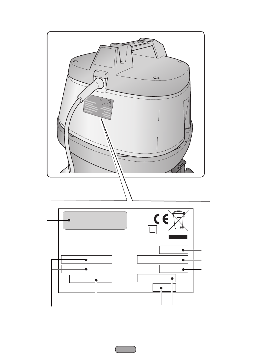
Mod.
Art.
Cap.ty
Vac mba
Air flow l/s
Nr
3
4
56
7
8
1
2
Copertina AS classic line-2012_CS6.indd 2 14/12/12 15.11

0 - 3
1 2 3 4 5 6 7 8
EN Manufacturer Model Article Container capacity Vacuum Air flow Serial N° Electrical characteristics
FR Producteur Modèle Article Capacité de la cuve Capacité d’aspiration Débit d’air N° Matricule Caractéristiques électriques
DE Hersteller Modell Artikel
Fassungsvermögen des Körpers
Ansaugleistung Luftdurchsatz Matrikelnr. Elektrische Eigenschaften
DK Fabrikant Model Artikel Beholdervolumen Sugeeffekt Luftmængde Matrikelnummer El-specifikationer
PL Producent Model Artykuł Pojemność zbiornika Podciśnienie (mbar) Przepływ powietrza Nr. Fabryczny Właściwości elektryczne
CZ Výrobce Model Typ Obsah nádoby Sací výkon Množství dopravovaného vzduchu Výrobní č. Elektrické údaje
RU Изготовитель Модель Артикул Емкость бака Мощность всасывания
Расход воздуха
Заводской № Электрические характеристики
Copertina AS classic line-2012_CS6.indd 3 14/12/12 15.11
0 - 4
Copertina AS classic line-2012_CS6.indd 4 14/12/12 15.11

0 - 5
0
I
0
I
0
I
Copertina AS classic line-2012_CS6.indd 5 14/12/12 15.11

0 - 6
Copertina AS classic line-2012_CS6.indd 6 14/12/12 15.11
0 - 7
■1000 W 62 dbA 190 mbar
■
PS 27 25 l 410 x 410
x 760
10,4 kg
Ø 40 mm
220~240V
Copertina AS classic line-2012_CS6.indd 7 14/12/12 15.11

Copertina AS classic line-2012_CS6.indd 8 14/12/12 15.11

0 - 9
EN
English
........................................................EN -5
(Translation of original instructions)
FR
Français
...................................................... FR -9
(Traduction des instructions d’origine)
DE
Deutsch
.....................................................DE -13
(Übersetzung der Originalanleitung)
DK
Dansk........................................................DK -33
(Oversættelse af original vejledning)
PL
Polski
......................................................... PL -41
(Tłumaczenie z oryginalnej instrukcji obsługi)
CZ
Česky
........................................................CS -45
(Překlad originálního návodu)
RU
Русский
.....................................................RU -69
(Перевод оригинальной инструкции)
Copertina AS classic line-2012_CS6.indd 9 14/12/12 15.26

Copertina AS classic line-2012_CS6.indd 10 14/12/12 15.11
This manual suits for next models
1
Table of contents
Languages:
Other Dr. Schutz Vacuum Cleaner manuals


