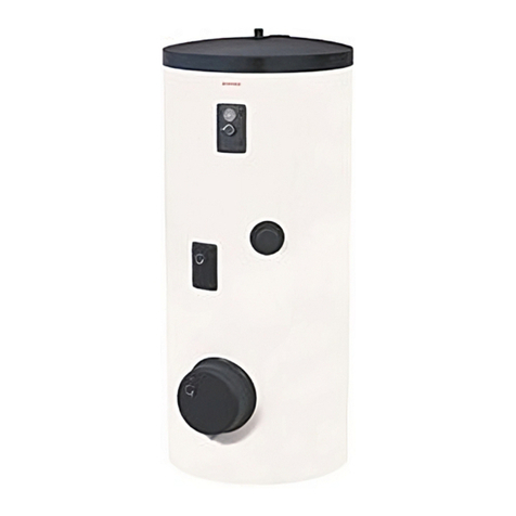
Drazice OKC 100 NTR User manual

OPERATING AND
INSTALLATION MANUAL
INDIRECT HOT WATER TANKS
OKC 80 NTR/Z
OKC 100 NTR OKC 100 NTR/HV OKC 100 NTR/Z
OKC 125 NTR OKC 125 NTR/HV OKC 125 NTR/Z OKCV 125 NTR
OKC 160 NTR OKC 160 NTR/HV OKC 160 NTR/Z OKCV 160 NTR
OKCV 180 NTR
OKC 200 NTR OKC 200 NTR/Z OKCV 200 NTR
OKC 250 NTR
OKC 200 NTRR
OKC 250 NTRR
Družstevní závody Dražice - strojírna s.r.o.
Dražice 69, 294 71 Benátky nad Jizerou
Phone.: +420 /326 370 990
Fax: +420 / 326 370 980
e-mail: prodej@dzd.cz

- 2 -
CONTENTS
1PRODUCT TECHNICAL SPECIFICATION....................................................................................................... 4
1.1 FUNCTION DESCRIPTION ................................................................................................................... 4
1.2 ADVICE FOR CUSTOMERS .................................................................................................................. 4
1.2.1 HOT WATER CONSUMPTION ..................................................................................................... 4
1.2.2 ENERGY SAVING......................................................................................................................... 4
1.2.3 EMERGENCY POWER CONSUMPTION ....................................................................................... 5
1.3 DESIGN AND GENERAL HEATER DIMENSIONS................................................................................... 6
2OPERATION AND FITTING INSTRUCTIONS............................................................................................... 17
2.1 OPERATING CONDITIONS ................................................................................................................ 17
2.2 WALL MOUNTING............................................................................................................................ 17
2.3 PLUMBING FIXTURE......................................................................................................................... 18
2.4 ELECTRICAL INSTALLATION.............................................................................................................. 21
2.4.1 GENERAL INFORMATION for ELECTRICAL INSTALLATION ....................................................... 21
2.4.2 ELECTRONIC THERMOSTAT WIRING METHODS ...................................................................... 21
2.5 CONNECTION OF INDIRECT TANK TO HOT WATER SYSTEM............................................................ 22
2.6 FIRST COMMISSIONING................................................................................................................... 22
2.7 PUTTING OUT OF SERVICE, DISCHARGE .......................................................................................... 23
2.8 INSPECTION, MAINTENANCE & CARE FOR THE APPLIANCE............................................................ 24
2.9 MOST FREQUENT FUNCTION FAILURES AND THEIR CAUSES .......................................................... 25
3OPERATION OF THEROMSTAT................................................................................................................. 25
3.1 SERVICING........................................................................................................................................ 25
3.1.1 OPERATING DEVICES OF THE TANK ......................................................................................... 25
3.1.2 TEMPERATURE SETTING .......................................................................................................... 27
4IMPORTANT NOTICES .............................................................................................................................. 28
4.1 INSTALLATION REGULATIONS.......................................................................................................... 28
4.2 SPARE PARTS.................................................................................................................................... 28
4.3 DISPOSAL OF PACKAGING MATERIAL AND NON-FUNCTIONING APPLIANCE .................................28

- 3 -
Meaning of pictograms used in the Manual
Important information for heater users.
Abiding by the recommendations of the manufacturer serves to ensure trouble-free
operation and the long service life of the product.
Caution!
Important notice to be observed.
CAREFULLY READ THIS MANUAL BEFORE INSTALLING THE WATER HEATER!
Dear Customer,
The Works Cooperative of Dražice – Machine Plant, Ltd., would
like to thank you for your decision to use a product of our
brand. With this guide, we will introduce you to the use,
construction, maintenance and other information on electrical
water heaters.
The manufacturer reserves the right for engineering modification of the product. The product is designed
for permanent contact with drinkable water.
It is recommended to use the product in indoor environment with air temperatures from +2°C to 45°C
and a relative humidity up to 80%. 80%.
Product’s reliability and safety is proven by tests implemented by the Engineering Test Institute in Brno.

- 4 -
1PRODUCT TECHNICAL SPECIFICATION
1.1 FUNCTION DESCRIPTION
Indirect stationary NTR and NTRR series TANKS are used to prepare HSW in combination with another hot
water supply, mostly gas boiler; in NTRR types in combination of two hot water sources (gas boiler + solar
system, heat pump). Their nominal performance provides sufficient amount of hot service water (HSW)
even for large flat units - premises, restaurants and similar establishments. In case of increased hot water
consumption, these tanks heat water continuously, operating similarly to flow heaters.
Closing valves of the heat exchanger must be opened which ensures heating water flow from the hot water
heating system. Together with closing valve, it is recommended to install an air outlet valve at the inlet to
the heat exchanger in order to bleed the heat exchanger as needed, in particular before the beginning of
the heating season (Figure 1, Figure 2, Figure 3, Figure 4 - by type). The time it takes to heat up using the
heat exchanger depends on the temperature and flow of water in the hot water heating system. A
combined tank is made in universal design – depending on the need of connecting the closing valves to the
heating element either from the right, or from the left.
1.2 ADVICE FOR CUSTOMERS
1.2.1 HOT WATER CONSUMPTION
Consumption of hot water in households depends on the number of people, amount of
sanitary equipment, length, diameter and insulation of piping in the flat, or on individual
habits of users. The cheapest option of water heating comes at the time when the
electricity rate is reduced.
Find out in what time intervals your electricity supplier provides reduced tariff and,
depending on that information, select relevant volume and power input of the heater so that
your hot water consumption covered the needs of your household.
1.2.2 ENERGY SAVING
Hot utility water reservoir is insulated by means of top-quality polyurethane foam with zero
CFCs content. Adjust the temperature of the heater's thermostat to that level only that you
need to run your home. Thus you will reduce electricity consumption, as well as the amount
of lime sediments on the walls of the receptacle and on the heat exchanger.
Benefits of using indirect heater:
-installation and connection to hot water supply,
-Very fast hot utility water heating,
-Enamelled steel tank ensures compliance with all hygienic requirements for the

- 5 -
quality of HSW,
-Integrated protective magnesium anode increases corrosion resistance,
-Quality polyurethane insulation ensures minimum heat losses,
-Smoothly settable HSW temperature up to 74°C,
-multiple supply points,
-in types with two exchangers, possibility of using two hot water supplies or, via a
combination of those, obtain double heat-transfer surface,
-light indication of the heater's run,
-HSW temperature control,
-Possibility of connecting HSW circulation.
1.2.3 EMERGENCY POWER CONSUMPTION
If no heated water is taken from the tank, a small amount of heat leaks. This loss is
measured for a period of 24 hours at the temperature of 65°C in the heater, and at 20°C in
its ambient area. The resulting value is expressed in units [kWh/24h] and indicates the
amount of power needed to maintain the set temperature. Data sheet - see Table 1.
TYPE
Heating
water flow
(l/h)
Pressure
loss (mbar)
OKC 100 NTR
720
33
OKC 125 NTR
46
OKC 160 NTR
46
OKC 200 NTR
46
OKC 250 NTR
46
OKC 200 NTRR
2 x 33
OKC 250 NTRR
2 x 33
Table 1

- 6 -
1.3 DESIGN AND GENERAL HEATER DIMENSIONS
The tank receptacle is made of steel plate and tested at 0.9 MPa of overpressure. The inside of the
receptacle is enamelled. A flange is welded onto the lower bottom of the receptacle with a flange lid
screwed onto it. A sealing ring is inserted between the flange lid and the flange. Thermowells for
thermostat sensors and thermometer installation are placed in the flange lid. An anode rod is mounted
onto the M8 nut. The water reservoir is insulated by means of polyurethane foam. Electric wiring is placed
underneath the plastic removable cover. The temperature of water can be set using the thermostat. Heat
exchanger(s) is/are welded onto the pressure tank.
Description of basic parts of the tank – by individual types (Figure 1, Figure 2, Figure 3, Figure 4).
Heater dimensions (Figure 5, Figure 6, Figure 7, Figure 8) and (Table 2, Table 4, Table 6, Table 8).
Technical description: OKC 100 NTR, OKC 125 NTR, OKC 160 NTR, OKC 200 NTR, OKC 250 NTR, OKC 200
NTRR, OKC 250 NTRR
Figure 1

- 7 -
Technical description: OKC 100 NTR/HV, OKC 125 NTR/HV, OKC 160 NTR/HV
Figure 2
Technical description: OKC 80 NTR/Z, OKC 100 NTR/Z, OKC 125 NTR/Z, OKC 160 NTR/Z, OKC 200 NTR/Z
Figure 3

- 8 -
Technical description: OKCV 125 NTR, OKCV 160 NTR, OKCV 180 NTR, OKCV 200 NTR
Figure 4

- 9 -
OKC 100 NTR, OKC 125 NTR, OKC 160 NTR OKC 200 NTR, OKC 250 NTR, OKC 200 NTRR,
OKC 250 NTRR
Figure 5
*Height from the upper heater's edge to the end of the water inlet and outlet tubes.
Table 2
OKC 100
NTR
OKC 125
NTR
OKC 160
NTR
OKC 200
NTR
OKC 200
NTRR
OKC 250
NTR
OKC 250
NTRR
A
902
1067
1255
1398
1398
1578
1578
B
891*
1058*
1249*
603
603
603
603
C
147
147
147
80
80
80
80
D
524
524
524
585
585
585
585
E
197
197
197
210
210
210
210
F
637
767
767
780
650
780
650
L
537
637
897
950
950
1060
1060
M
-
-
-
-
710
-
890
N
-
-
-
-
1150
-
1330
O
-
-
-
1280
1280
1460
1460

- 10 -
Table 3
TYPE
OKC 100
NTR
OKC 125
NTR
OKC 160
NTR
OKC 200
NTR
OKC 200
NTRR
OKC 250
NTR
OKC 250
NTRR
VOLUME
L
87
112
148
208
200
242
234
MAX OPERATING
OVERPRESSURE IN THE
TANK
MPa 0,6
MAX OPERATING
OVERPRESSURE IN THE
EXCHANGER
MPa 1
ELECTRICAL
CONNECTION OF
CONTROL ELEMENTS
1 PE-N 230V/50Hz
EL. PROTECTION
IP 42
MAX TEMPERATURE
TUV °C 80
RECOMMENDED HSW
TEMPERATURE °C 60
MAX WEIGHT OF THE
HEATER WITHOUT
WATER
kg 57 69 77 95 108 107 118
EXCHANGER HEAT
TRANSFER SURFACE m21,08 1,45 1,45 1,45 2 x 1.08 1,45 2x 1.08
RATED THERMAL
OUTPUT AT HEATING
WATER TEMPERATURE
OF 80°C AND FLOW 720
L/H
W 24000 32000 32000 32000 2 x
24000 32000 2 x
24000
TIME OF HEATING BY
EXCHANGER FROM 10°C
TO 60°C
min 14 14 17 22 28 / 1628 36 / 20
STATIC LOSS
W
42
54
75
82
82
87
87

- 11 -
OKC 100 NTR/HV, OKC 125 NTR/HV, OKC 160 NTR/HV
Figure 6
*Height from the upper heater's edge to the end of the water inlet and outlet tubes.
Table 4
neck #1 3/4" outer
neck #2 3/4" outer
neck #3
3/4" outer
neck #4
3/4" outer
neck #5
3/4" outer
neck #6 1/2" inner
TYPE
OKC 100 NTR/HV
OKC 125 NTR/HV
OKC 160 NTR/HV
A
902
1067
1092
B*
893
1058
1079
C
144
144
146
D
524
524
584
E
165
165
165
F
119
119
119
G
182
182
182

- 12 -
Table 5
TYPE
OKC 100
NTR/HV
OKC 125
NTR/HV
OKC 160
NTR/HV
VOLUME
L
87
113
144
MAX OPERATING OVERPRESSURE IN THE TANK
MPa
0,6
MAX OPERATING OVERPRESSURE IN THE
EXCHANGER MPa 1
ELECTRICAL CONNECTION OF CONTROL ELEMENTS
1 PE-N 230 V/50Hz
EL. PROTECTION
IP 42
MAX TEMPERATURE TUV
°C
80
RECOMMENDED HSW TEMPERATURE
°C
60
MAX WEIGHT OF THE HEATER WITHOUT WATER
kg
56
70
78
EXCHANGER HEAT TRANSFER SURFACE
m2
1,08
1,45
1,45
RATED THERMAL OUTPUT AT HEATING WATER
TEMPERATURE 80°C AND FLOW 720 l/h W 24000 32000 32000
TIME OF HEATING BY EXCHANGER FROM 10°C TO
60°C min 14 14 17
STATIC LOSS
W
42
65
65

- 13 -
OKC 80 NTR/Z, OKC 100 NTR/Z, OKC 125 NTR/Z
OKC 160 NTR/Z, OKC 200 NTR/Z
Figure 7
Table 6
①
3/4" outer
②
1" outer
③
3/4" inner
TYPE
OKC 80
NTR/Z
OKC 100
NTR/Z
OKC 125
NTR/Z
OKC 160
NTR/Z
OKC 200
NTR/Z
A
757
902
1067
1255
1287
B*
748
893
1058
1246
1277
C
615
765
763
1001
795
D
524
524
524
524
584
E
-
-
-
186
195
F
70
70
70
70
70
G
172
172
172
172
172
H
498
648
648
700
678
I
208
208
208
258
238
J
-
438
498
828
888
R
450
450
450
450
450

- 14 -
TYPE
OKC 80
NTR/Z
OKC 100
NTR/Z
OKC 125
NTR/Z
OKC 160
NTR/Z
OKC 200
NTR/Z
VOLUME
L
76
95
120
148
196
MAX OPERATING
OVERPRESSURE
IN THE TANK
MPa 0,6
MAX OPERATING
OVERPRESSURE
IN THE
EXCHANGER
MPa 1
ELECTRICAL
CONNECTION OF
CONTROL
ELEMENTS
1 PE-N 230V/50Hz
EL. PROTECTION
IP 44
MAX
TEMPERATURE
TUV
°C 80
RECOMMENDED
HSW
TEMPERATURE
°C 60
HEIGHT OF THE
HEATER mm 736 881 1046 1235 1287
DIAMETER OF THE
HEATER mm 524 524 524 524 584
MAX WEIGHT OF
THE HEATER
WITHOUT WATER
kg 39 56 62 70 87
EXCHANGER HEAT
TRANSFER
SURFACE
m20,41 1,08 1,08 1,08 1,08
RATED THERMAL
OUTPUT AT
HEATING WATER
TEMPERATURE
80°C AND FLOW
720 l/h
W9000 24000 24000 24000 24000
TIME OF HEATING
BY EXCHANGER
FROM 10°C TO
60°C
min 32 14 17 23 28
STATIC LOSS
W
40
47
57
67
72
Table 7

- 15 -
OKCV 125 NTR, OKCV 160 NTR, OKCV 180 NTR, OKCV 200 NTR
Figure 8
Table 8
①
3/4" inner
TYPE
OKCV 125 NTR
OKCV 160 NTR
OKCV 180 NTR
OKCV 200 NTR
A
1067
1255
1187
1287
B
600
700
600
600
C
954
1013
936
936
D
524
524
584
584
E
204
254
258
258
F
226
226
246
246
G
232
232
256
256
H
556
556
618
618
I
513
649
570
670
J
439
439
439
439

- 16 -
TYPE
OKCV 125 NTR
OKCV 160 NTR
OKCV 180 NTR
OKCV 200 NTR
VOLUME
L
123
151
173
200
MAX OPERATING
OVERPRESSURE IN
THE TANK
MPa 0,6
MAX OPERATING
OVERPRESSURE IN
THE EXCHANGER
MPa 0,4
ELECTRICAL
CONNECTION OF
CONTROL ELEMENTS
1 PE-N 230 V/50Hz
EL. PROTECTION
IP 42
MAX TEMPERATURE
TUV °C 80
RECOMMENDED
HSW TEMPERATURE °C 60
MAX WEIGHT OF THE
HEATER WITHOUT
WATER
kg 55 65 76 80
EXCHANGER HEAT
TRANSFER SURFACE m20,7 0,7 0,75 0,75
RATED THERMAL
OUTPUT AT HEATING
WATER
TEMPERATURE 80°C
AND FLOW 720 l/h
W15000 16800 18000 18000
TIME OF HEATING BY
EXCHANGER FROM
10°C TO 60°C
min 37 35 38 43
RATED THERMAL
OUTPUT AT HEATING
WATER
TEMPERATURE OF
80°C AND FLOW 310
L/H
W8000 10260 11000 11000
TIME OF HEATING BY
EXCHANGER FROM
10°C TO 60°C
min 70 60 63 72
STATIC LOSS
W
70
77
98
93
Table 9

- 17 -
2OPERATION AND FITTING INSTRUCTIONS
2.1 OPERATING CONDITIONS
The tank shall only be used in accordance with the conditions specified on the performance
plate and in instructions for electric wiring. Besides legally acknowledged national
regulations and standards, also conditions for connection defined in local electric and water
works have to be adhered to, as well as the installation and operation manual. The room, in
which the appliance will be operated, must be frost-free. The appliance has to be mounted
at a convenient place, it means that the appliance must be easily available for potential
necessary maintenance, repair or replacement, as the case may be.
We emphasize that the tank shall not be connected to power supply if flammable liquids
(benzine, stain cleaner) or gases, etc., are handled in its proximity.
If water is strongly calcareous we recommend that any of the common decalcifying devices
was installed with the appliance, or that the thermostat was set to the minimum operating
temperature of 60oC. For proper operation, drinkable water of adequate quality shall be
used. To avoid potential sediments we recommend that the device was installed together
with a water filter.
2.2 WALL MOUNTING
Prior to mounting, check the loading capacity of the wall and, depending on the type of
masonry, choose a suitable anchorage material, or reinforce the wall, if needed. The NTR/Z
water heater shall only be mounted in vertical position so that the lower edge of the tank
was placed at least 600 mm above the floor. The OKCV NTR water heater shall only be
mounted in horizontal position so that from the front view, the right edge of the tank was
placed at least 600 mm from the opposite wall. In combined tanks, elbows have to be
attached to the heating water inlet and outlet and, by turning them, the mounting either
from the right or from the left has to be determined (Figure 9). With regard to various types
of bearing masonry and wide range of special anchorage material available at the market,
we do not provide the tanks with that material. The anchorage system has to be selected
individually, depending on the conditions. We recommend an authorised company perform
mounting on the wall and anchorage, or discuss the anchorage with a professional.
If hot water tank is mounted in a tight, smaller space, or in an intermediate ceiling, etc., you
have to make sure that the connecting side of the appliance (connections to water supply,
area for electric plugging) remained accessible and no heat accumulation occurs. Free space
of up to 600 mm from the bottom edge of the tank has to be available under the tank.

- 18 -
Figure 9
2.3 PLUMBING FIXTURE
Tanks are connected to plumbing fixtures as shown in (Figure 10, Figure 11, Figure 12). For
potential disconnection of the tank, utility water inlets and outlets must be provided with Js
3/4“ screw coupling. If the hot utility water (HSW) distribution is equipped with circulation
circuit, the reverse pipe is connected to the inlet identified as CIRCULATION. Types 100, 125,
160 NTR and 100, 125, 160 NTR / HV are equipped with drain outlet. In 200 and 250 NTR(R)
types, the HSW inlet has to be provided with a “T” fixture with a drain valve. The tank shall
be equipped with safety valve to ensure operation. The safety valve is mounted on the cold
water inlet identified with a blue ring.
Every hot utility water pressure tank shall be equipped with membrane spring loaded with
safety valve. Safety valve shall be easily accessible, fitted as close as possible to the tank. The
inlet pipes must have at least the same clearance as the safety valve. Safety valve is placed
high enough to secure dripping water drain by gravity. We recommend mounting the safety
valve onto a branch pipe. This allows easier exchange without having to drain the water from
the heater. Safety valves with fixed pressure settings from the manufacturer are used for the
assembly. The starting pressure of the safety valve must be identical to the maximum
allowed pressure of the tank, and at least 20 % higher than is the maximum pressure in the
water main (Table 10). If the water main pressure exceeds such value, a reduction valve
must be added to the system. No closing armature may be mounted between the tank and
the safety valve. During assembly, follow the guide provided by the safety equipment
manufacturer.

- 19 -
It is necessary to check the safety valve each time before putting it into operation. It is
checked by manual moving of the membrane from the seat, turning the make-and-break
device button always in the direction of the arrow. After being turned, the button must click
back into a notch. Proper function of the make-and-break device results in water draining
through the safety valve outlet pipe. In regular operation, such a check needs to be carried
out at least once a month, and after each shutdown of the tank longer than 5 days. Water
may be dripping off the drain pipe of the safety valve; the pipe must be open into the air,
pointed down; environment temperatures must not drop below zero. When draining the
tank, use the recommended drain valve. First of all, close water inlet in the tank. Find
necessary pressure values in the following table. For proper safety valve operation, a
backflow valve shall be mounted on the inlet pipes, preventing spontaneous heater draining
of the tank and hot water penetration back into the water main.
Required pressures - Table 10 - We recommend that the hot water distribution from the tank is as short as
possible in order to reduce heat losses.
Table 10
Tanks must be provided with a discharge valve mounted on the cold service water inlet to the heater for
potential disassembly or repair
SAFETY VALVE STARTING PRESSURE
(MPa)
ACCEPTABLE OPERATING OVER-
PRESSURE OF THE WATER HEATER
(MPa)
MAX COLD WATER PRESSURE IN
PIPING (MPa)
0,6
0,6
up to 0.48
0,7
0,7
up to 0.56
1
1
up to 0.8
FIgure 1

- 20 -
O - bleeder valve
U - stop valve
P1 – safety valve with reverse flap
P2 - safety valve for heating circuit
M – manometer
Z - test valve
V - drain valve
Figure 2
Other manuals for OKC 100 NTR
3
This manual suits for next models
17
Table of contents
Other Drazice Boiler manuals
Popular Boiler manuals by other brands

Raypak
Raypak MVB TYPE B 504-2004 Installation & operating instructions

Viessmann
Viessmann VITOTRANS 353 operating instructions

FULTON
FULTON Endura XE Installation, operation and maintenance manual

PEERLESS
PEERLESS PureFire PF-200 Installation, operation & maintenance manual

Bradford White
Bradford White Brute LX BLXCW-125 user manual

Crown Boiler
Crown Boiler BERMUDA BSI172 installation instructions