Vivadens MCR-P 34/39 MI User manual
Vivadens EN
Wall-hung gas condensing boilers
MCR-P 24
MCR-P 24/28 MI
MCR-P 30/35 MI
MCR-P 34/39 MI
User Guide
127684-01

Contents
1 Introduction ................................................................................................4
1.1 Symbols used .......................................................4
1.2 Abbreviations ........................................................4
1.3 General ..................................................................5
1.3.1 Manufacturer’s liability .............................................5
1.3.2 Installer’s liability .....................................................5
1.4 Homologations ......................................................5
1.4.1 Certifications ...........................................................5
1.4.2 Gas categories ........................................................6
1.4.3 Additional Directives ................................................6
1.4.4 Factory test .............................................................6
2Safety instructions and recommendations ..............................................7
2.1 Safety instructions ...............................................7
2.2 Recommendations ................................................7
3Description ..................................................................................................9
3.1 General description ..............................................9
3.2 Main parts ..............................................................9
3.3 Control panel .......................................................10
4 Operating the appliance ..........................................................................11
4.1 Start the boiler ....................................................11
4.2 Reading out measured values ...........................12
4.3 Changing the settings ........................................13
4.3.1 Changing the heating temperature ........................13
4.3.2 Changing the domestic hot water
temperature ...........................................................14
4.3.3 Modifying the comfort setting (ECO) .....................14
4.3.4 Stopping the central heating or activating the Summer
mode .....................................................................15
4.3.5 Stopping domestic hot water production ...............16
4.3.6 Other settings ........................................................16
1070513 - 127684-01

4.4 Installation shutdown .........................................17
4.5 Turning on the antifreeze function ....................18
5 Checking and maintenance .....................................................................19
5.1 General instructions ...........................................19
5.2 Periodic checks ..................................................19
5.3 Filling the system ...............................................20
5.4 Bleeding the heating system .............................21
5.5 Draining the installation .....................................23
6 Troubleshooting .......................................................................................25
6.1 Error codes ..........................................................25
6.1.1 e01 - e02 - e07 - e09 ......................25
6.1.2 e04 ...................................................................25
6.1.3 Other error codes ..................................................25
6.1.4 Before contacting the installer ...............................26
6.2 Incidents and solutions ......................................26
7 Technical specifications ..........................................................................28
7.1 Technical specifications ....................................28
8 Energy savings .........................................................................................30
8.1 Energy savings ...................................................30
8.1.1 Energy-saving advice ............................................30
8.1.2 Room thermostat and settings ..............................30
9 Warranty ....................................................................................................32
9.1 General ................................................................32
9.2 Warranty terms ...................................................32
Contents
2070513 - 127684-01

3070513 - 127684-01

1 Introduction
1.1 Symbols used
In these instructions, various danger levels are employed to draw the
user’s attention to particular information. In so doing, we wish to
safeguard the user’s safety, obviate hazards and guarantee correct
operation of the appliance.
DANGER
Risk of a dangerous situation causing serious physical
injury.
WARNING
Risk of a dangerous situation causing slight physical
injury.
CAUTION
Risk of material damage.
Signals important information.
¼Signals a referral to other instructions or other pages in the
instructions.
1.2 Abbreviations
4DHW: Domestic hot water.
4PPS: Polypropylene hardly inflammable.
43CE: Collective conduit for sealed boiler.
4IRC: Interactive remote control.
4CRC: Communicating remote controller.
4Hi: Lower heating value LHV (Nett).
4Hs: Higher heating value HHV (Gross).
MCR-P 24 MCR-P 24/28 MI MCR-P 30/35 MI MCR-P 34/39 MI 1. Introduction
070513 - 127684-01 4

1.3 General
1.3.1. Manufacturer’s liability
Our products are manufactured in compliance with the requirements
of the various applicable European Directives. They are therefore
delivered with [ marking and all relevant documentation.
In the interest of customers, we are continuously endeavouring to
make improvements in product quality. All the specifications stated in
this document are therefore subject to change without notice.
Our liability as the manufacturer may not be invoked in the following
cases:
4Failure to abide by the instructions on using the appliance.
4Faulty or insufficient maintenance of the appliance.
4Failure to abide by the instructions on installing the appliance.
1.3.2. Installer’s liability
The installer is responsible for the installation and inital start up of the
appliance. The installer must respect the following instructions:
4Read and follow the instructions given in the manuals provided
with the appliance.
4Carry out installation in compliance with the prevailing legislation
and standards.
4Perform the initial start up and carry out any checks necessary.
4Explain the installation to the user.
4If a maintenance is necessary, warn the user of the obligation to
check the appliance and maintain it in good working order.
4Give all the instruction manuals to the user.
1.4 Homologations
1.4.1. Certifications
CE identification no PIN 0063BQ3009
NOx < 70 mg/kWh
Type of connection Chimney: B23
Flue gas outlet: C13,C33,C43,C53,C63,C83, C93
1. Introduction MCR-P 24 MCR-P 24/28 MI MCR-P 30/35 MI MCR-P 34/39 MI
5070513 - 127684-01

1.4.2. Gas categories
Gas category Gas type Connection pressure (mbar) Countries
II2H3P Natural gas H (G20) 20 All countries except China
Propane (G31) 50 Bulgaria, Romania
37/50 Czech Republic, Spain
30 Finland, Norway, Slovenia
30/37 Greece, Italy
37 Portugal
30/50 Russia
I2H Natural gas H (G20) 20 China
The boiler is preset in the factory to operate on natural gas H (G20).
1.4.3. Additional Directives
Apart from the legal provisions and Directives, the additional
Directives described in these instructions must also be observed.
For all provisions and Directives referred to in these instructions, it is
agreed that all addenda or subsequent provisions will apply at the
time of installation.
WARNING
Installation of the appliance must be done by a qualified
engineer in accordance with prevailing local and national
regulations.
1.4.4. Factory test
Before leaving the factory, each boiler is set for optimum performance
and tested to check the following items:
4Electrical safety
4Adjustment (CO2)
4Domestic hot water mode (Only on models with domestic hot water
production)
4Water tightness
4Gas tightness
4Parameter settings
MCR-P 24 MCR-P 24/28 MI MCR-P 30/35 MI MCR-P 34/39 MI 1. Introduction
070513 - 127684-01 6

2 Safety instructions and
recommendations
2.1 Safety instructions
DANGER
If you smell gas:
1. Do not use a naked flame, do not smoke, do not
operate electrical contacts or switches ( doorbell,
light, motor, lift, etc..).
2. Shut off the gas supply.
3. Open the windows.
4. Trace possible leaks and seal them immediately.
5. If the gas leak is before the gas meter, contact the
gas supplier.
DANGER
If you smell flue gases:
1. Switch the appliance off.
2. Open the windows.
3. Trace possible leaks and seal them immediately.
2.2 Recommendations
WARNING
4Installation and maintenance of the boiler must be
carried out by a qualified professional in compliance
with prevailing local and national regulations.
4When working on the boiler, always disconnect the
boiler from the mains and close the main gas inlet
valve.
4After maintenance or repair work, check all
installations to ensure that there are no leaks.
CAUTION
The boiler must be installed in a frost-free environment.
Keep this document close to the place where the boiler is
installed.
Casing components
2. Safety instructions and recommendations MCR-P 24 MCR-P 24/28 MI MCR-P 30/35 MI MCR-P 34/39 MI
7070513 - 127684-01

Only remove the casing for maintenance and repair operations. Put
the casing back in place after maintenance and repair operations.
Instructions stickers
The instructions and warnings affixed to the appliance must never be
removed or covered and must remain legible during the entire lifespan
of the appliance. Immediately replace damaged or illegible
instructions and warning stickers.
Modifications
Modifications may only be made to the boiler after the written
permission of De Dietrich Thermique to do so.
MCR-P 24 MCR-P 24/28 MI MCR-P 30/35 MI MCR-P 34/39 MI 2. Safety instructions and recommendations
070513 - 127684-01 8
3 Description
3.1 General description
Wall-hung gas condensing boilers
4MCR-P 24 - Heating only.
4MCR-P ... MI - Heating and instantaneous domestic hot water
production.
4Low pollutant emissions.
4Flue gas discharge via a forced flue, chimney, bi-flow or 3CE type
connection.
The MCR-P 24 boiler can be connected to a 80 or 130 litre tank to
produce domestic hot water.
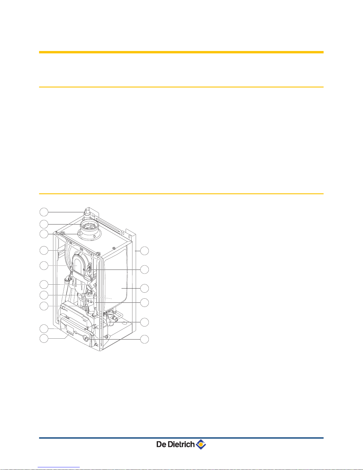
3.2 Main parts
1Automatic air vent
2Flue gas discharge pipe / Combustive air
3Outlet for measuring combustion gases
4Heat exchanger
5Air/gaz canal
6Fan air inlet
7Water pressure sensor
8Gas block
9Display
10 Control panel
11 Pressure gauge
12 Circulating pump
13 Ignition transformer
14 Expansion vessel heating circuit
(Except MCR-P 34/39 MI model )
15 Ignition/ionization electrode
16 Stand-off frame (optional)
R000232-A
13
15
16
14
12
11
4
2
1
3
5
6
7
8
9
10
3. Description MCR-P 24 MCR-P 24/28 MI MCR-P 30/35 MI MCR-P 34/39 MI
9070513 - 127684-01
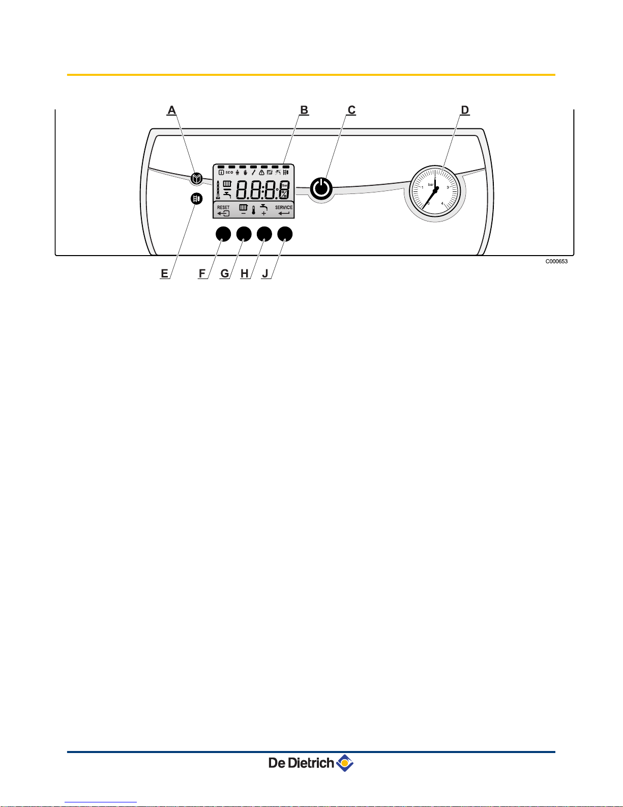
3.3 Control panel
AMenu key
BDisplay
CMain ON/OFF switch
DPressure gauge
ESweep key
F( or RESET key
GHeating temperature key or -
HDHW temperature key or +
JSERVICE or U key
The display indicates the state of the boiler and any errors. The
symbols located above the function keys indicate their current
function.
Pressing on any key will display the current status of the boiler and
the current command code. If there is a fault, the corresponding code
continues to be displayed.
MCR-P 24 MCR-P 24/28 MI MCR-P 30/35 MI MCR-P 34/39 MI 3. Description
070513 - 127684-01 10

4 Operating the appliance
4.1 Start the boiler
1. Check the water pressure in the installation.
2. Open the gas valve.
3. Throw the boiler’s ON / OFF switch.
4. The start-up cycle begins. It lasts 2 minutes and cannot be
interrupted.
During the start-up cycle, the display shows the following
information:
fK[xx: Software version
pK[xx: Parameter version
The version numbers are displayed alternately.
5. When the start-up cycle is finished, the display shows 0. The
boiler is now operational.
A000785-A
A000787-A
4. Operating the appliance MCR-P 24 MCR-P 24/28 MI MCR-P 30/35 MI MCR-P 34/39 MI
11 070513 - 127684-01

4.2 Reading out measured values
The following values can be displayed in the information menu Q:
4t1 = Flow temperature (°C)
4t2 = Return temperature (°C)
4t3 = Domestic hot water temperature (°C)
4t4 = Outside temperature (°C)
4fl = Ionization current (μA)
4Mf = Fan speed (rpm)
1. Press the f key. The symbol Q flashes.
2. To access the parameters, press key S.
3. Press the [+] key successively to scroll down the various
parameters.
4. Press the > key 2 times to return to the current operating mode
T000138-A
MCR-P 24 MCR-P 24/28 MI MCR-P 30/35 MI MCR-P 34/39 MI 4. Operating the appliance
070513 - 127684-01 12

4.3 Changing the settings
4.3.1. Changing the heating temperature
If an outside temperature sensor or an OpenTherm control
system is fitted, the heating flow temperature is adjusted
automatically.
In summer, it is possible to reduce the heating flow temperature whilst
maintaining comfort. To do this, proceed as follows:
1. Press the D key.
The symbol D and the current temperature are displayed.
2. Use the [+] and [-] keys to change the parameter value.
3. To confirm the new value, press the key S.
It also possible to modify this setting using the parameter
p1. ¼See chapter: "Other settings", page 16.
T000147-A
GA,
HF,
4. Operating the appliance MCR-P 24 MCR-P 24/28 MI MCR-P 30/35 MI MCR-P 34/39 MI
13 070513 - 127684-01
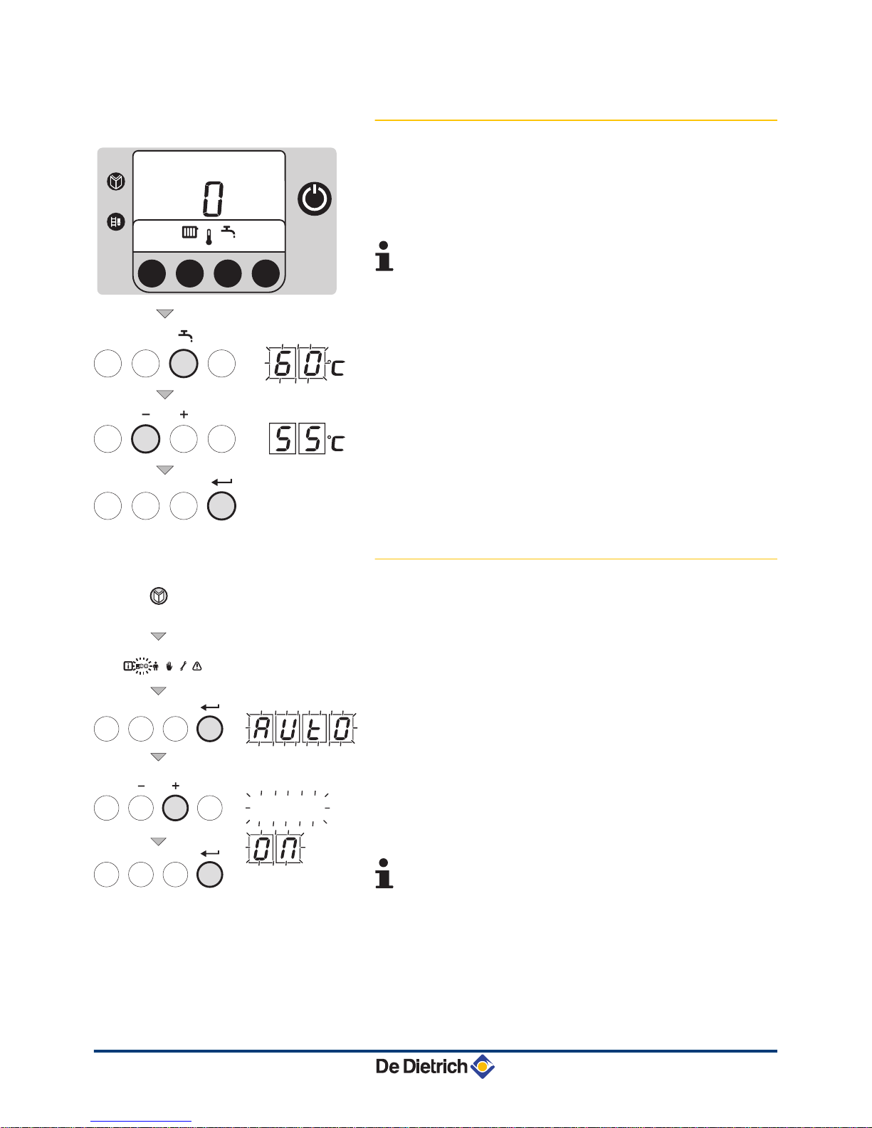
4.3.2. Changing the domestic hot water
temperature
1. Press the N key.
The symbol N and the current temperature are displayed.
2. Use the [+] and [-] keys to change the parameter value.
3. To confirm the new value, press the key S.
It also possible to modify this setting using the parameter
p2. ¼See chapter: "Other settings", page 16.
4.3.3. Modifying the comfort setting (ECO)
The user can consult or modify the following 3 settings:
4ON = Activation of the energy-saving setting.
4OFF = Activation of the comfort setting.
4AUTO = Setting dependent on the control unit (Factory setting).
1. Press the f key 1 times. The symbol Q flashes.
2. Press the f key a second time. The symbol ECO flashes.
3. To confirm, press the S key.
4. The current operating status is shown on the display:AUTO.
5. Use the + and - keys to change the parameter value.
6. To confirm, press the S key.
7. Press the > key 2 times to return to the current operating
mode.
It also possible to modify this setting using the parameter
p4. ¼See chapter: "Other settings", page 16.
T000143-A
Ajj
2x
T000148-B
MCR-P 24 MCR-P 24/28 MI MCR-P 30/35 MI MCR-P 34/39 MI 4. Operating the appliance
070513 - 127684-01 14
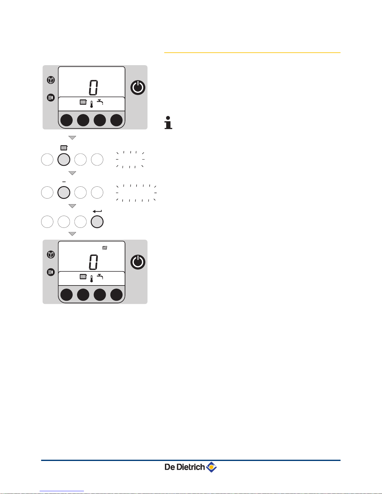
4.3.4. Stopping the central heating or activating
the Summer mode
1. Press the D key.
The symbol D and the current temperature are displayed.
2. Press the key [-] several times until the value 0ff is displayed.
3. To confirm the new value, press the key S.
The symbol C appears.
4It also possible to modify this setting using the
parameter p3. ¼See chapter: Unresolved Cha
internal-destination[ 1834] .
4Domestic hot water production is maintained.
HF,
Ajj
T000141-A
4. Operating the appliance MCR-P 24 MCR-P 24/28 MI MCR-P 30/35 MI MCR-P 34/39 MI
15 070513 - 127684-01

4.3.5. Stopping domestic hot water production
1. Press the N key.
The symbol N and the current temperature are displayed.
2. Press the key [-] several times until the value 0ff is displayed.
3. To confirm the new value, press the key S.
The symbol T appears.
It also possible to modify this setting using the parameter
p3. ¼See chapter: Unresolved Cha internal-
destination[ 1834] .
4.3.6. Other settings
Parameter Description Adjustment range
Factory setting
MCR-P 24 MCR-P
24/28 MI
MCR-P
30/35 MI
MCR-P
34/39 MI
p1 Flow temperature 20 to 85 °C 75 °C 75 °C 75 °C 75 °C
p2 Domestic hot water
temperature 40 to 65 °C 55 °C 55 °C 55 °C 55 °C
p3 Heating / DHW mode
0 = Heating deactivated (C) / DHW
deactivated (T)
2 1 1 1
1 = Heating activated (D) / DHW
activated (N)
2 = Heating activated (D) / DHW
deactivated (T)
3 = Heating deactivated (C) / DHW
activated (N)
GA,
Ajj
T000142-A
MCR-P 24 MCR-P 24/28 MI MCR-P 30/35 MI MCR-P 34/39 MI 4. Operating the appliance
070513 - 127684-01 16

Parameter Description Adjustment range
Factory setting
MCR-P 24 MCR-P
24/28 MI
MCR-P
30/35 MI
MCR-P
34/39 MI
p4 ECO mode
0 = Comfort mode
2 2 2 2
1 = Energy-saving mode
2 = Management using a
programmable thermostat
p5 Anticipation
resistance
0 = No anticipation resistance for the
ON/OFF thermostat 0 0 0 0
1 = Anticipation resistance for the ON/
OFF thermostat
p6 Display screen
0 = The screen stays off
2 2 2 2
1 = The screen stays on
2 = The screen switches off
automatically after 3 minutes
To change these parameters, proceed as follows:
1. Press key f several times until the symbol W flashes on the menu
bar.
2. Press the S key to enter the "User" menu.
The symbol p[1 appears.
3. Use the + and - keys to select to parameter to be changed.
4. Press the S key to display the parameter value selected.
5. Use the + and - keys to change the parameter value.
6. To confirm the new value, press the key S.
The name of the modified parameter is displayed.
7. If necessary, set other parameters by selecting them using the +
or - keys.
8. To exit the User menu, press the > key 2 times.
If no selections are made in the various modes for 10
minutes, the boiler resumes the settings prior to
manipulation.
4.4 Installation shutdown
If the central heating system is not used for a long period, we
recommend switching the boiler off.
1. Switch the boiler off.
2. Switch off the boiler electrical power supply.
3. Close the gas valve.
4. Ensure that the boiler and system are protected against frost
damage.
2x
3x
T000307-A
4. Operating the appliance MCR-P 24 MCR-P 24/28 MI MCR-P 30/35 MI MCR-P 34/39 MI
17 070513 - 127684-01
4.5 Turning on the antifreeze function
We recommend setting the boiler thermostat to a value off 10°C if
using a classic installation.
Define parameter p4 as 1 (energy-saving mode), the heat
retention function will be deactivated.
Installation and room antifreeze protection is guaranteed if you are
absent.
If the temperature of the central heating water in the boiler falls too
much, the integrated protection device switches itself on:
4If the water temperature is lower than 7°C, the circulating pump is
activated.
4If the water temperature is lower than 3°C, the boiler is activated.
4When the water temperature is above 10 °C, the boiler is switched
off and the circulation pump runs for another 15 minutes.
CAUTION
This function is a protection device for the boiler only, not
for the system or buiding fabric.
CAUTION
If a room thermostat, connected via connectors 7 and 8,
is activated, the boiler will operate permanently until it
reaches the flow setting point.
MCR-P 24 MCR-P 24/28 MI MCR-P 30/35 MI MCR-P 34/39 MI 4. Operating the appliance
070513 - 127684-01 18

5 Checking and maintenance
5.1 General instructions
CAUTION
4An annual inspection is compulsory.
4We recommend taking out a maintenance contract.
4Maintenance operations must be done by a qualified
engineer.
4Only original spare parts must be used.
4Make certain that the flues and chimneys are
connected, in good condition and not blocked.
4Do not modify nor block the condensate outlet(s).
4If a neutralisation system is installed, follow the
instructions delivered with the neutralisation system
for cleaning and servicing of this system.
5.2 Periodic checks
4Check the water pressure in the installation. If the water pressure
is too low, add more water to the installation. ¼See chapter:
"Filling the system", page 20.
4Carry out a visual check for the presence of any water leaks.
4Open and close the radiator valves several times a year (this
prevents the valves from seizing up).
1
2
3
4
T000181-B
5. Checking and maintenance MCR-P 24 MCR-P 24/28 MI MCR-P 30/35 MI MCR-P 34/39 MI
19 070513 - 127684-01
Table of contents
Other Vivadens Boiler manuals


Popular Boiler manuals by other brands


Alpha
Alpha al357i-b instruction manual

Ariston
Ariston GENUS 27 RFFI SYSTEM installation instructions

FULTON
FULTON FBW-IOM-2014-0311 Installation and operation manual

Riello
Riello Caldariello Condens 25 KIS installer and user manual

Crown
Crown CRN30 Operating & installation instructions

Lochinvar
Lochinvar Crest w/RealTime O2 Trim 100 Series Service manual

Intergas
Intergas Xclusive 24 Service Procedure

Biasi
Biasi Riva ADVANCE SV owner's manual

Effecta
Effecta Smart 40 Installation, maintenance, service, assembly

Watts
Watts AERCO CFR 3000 Operator's and service manual

Viessmann
Viessmann Vitorond 200 VD2 320 Service instructions

Baxi
Baxi Eco5 Compact+ Operating and installation instructions