manuals.online logo
Brands
  1. Home
  2. •
  3. Brands
  4. •
  5. AIC
  6. •
  7. Boiler
  8. •
  9. AIC COILMASTER 35 User manual

AIC COILMASTER 35 User manual

heatingsystems
EN
Z-090481 • 00
COILMASTER 35 - 45 Gas Conversion Procedure
After gas conversion is performed,
control the gas pressure and consump-
tion at appliance start up, and perform
the adjustment procedures provided in
“Adjustment of Fan Speeds” on page
3and “Combustion Adjustment”
on page 4.
i
Summary
This procedure consists in replacing the facto-
ry-installed air-gas mixer for G20 natural gas at-
tached to the fan, by an air-gas mixer for either
G25 natural gas or G31 liqueed gas (Propane).
See Fig. 1 opposite for air-gas mixer location.
See table below for air-gas mixer top and bottom
injector sizes:
Air-gas mixer (Venturi)
Fig. 1. Component Location
Models
G25
Top - Bottom
G31
Top - Bottom
CM 35 / 45 4.3 - 5.4 3.3 - 3.4
îMake sure that the gas type and pres-
sure of the distribution network are com-
patible with the appliance, as per the
information on the appliance data plate.
îIf the boiler was running before conversion,
allow it to cool down before performing any
task.
îConversion of the appliance from one
gas type to another can only be per-
formed by a qualied professional.
îGas conversion shall be performed
according to applicable local reg-
ulations. It is prohibited in some
countries. Perform conversion ac-
cording to the gas category spec-
ied for your country on the appli-
ance data plate.
îIf the boiler is intended to be used
with liqueed gas (propane), in-
stalling the boiler below ground
level can be hazardous and prohib-
ited in some countries. Please refer
to applicable local regulations for
installation requirements.
îIf the boiler is already installed before
conversion, the boiler must be turned
o, the power supply must be dis-
connected through the external fuse
or circuit breaker, and the gas supply
to the gas valve must be closed.
2Z-090481_EN • 00
CoilMaster 35 - 45 - Gas Conversion ProCedure
Air-Gas Mixer Replacement
Conditions:
îBoiler turned o using the appliance on/o switch
îPower supply deactivated through external electrical
box (fuse or circuit breaker)
îGas supply shut down
îBoiler cooled down
îFront and top panel removed. Please refer to the Installa-
tion and Maintenance Manual for the correct procedure.
Tools and material:
îWrench, hex head
îScrewdriver, at
îTorque wrench
îProtective gloves
Air-Gas Mixer Removal Procedure (Fig. 2)
1. Disconnect gas supply from boiler gas connection.
2. Disconnect all connectors and ground wires from
the electrodes and the fan.
3. Wearing protective gloves, remove rock wool in-
sulation from the upper plate. Retain for reinstal-
lation.
4. Disconnect the air inlet duct (1) from the air-gas
mixer (6) and the ue box (8).
5. Release gas tube union (2) from gas valve (3).
Check the gasket (5) condition and replace as
required.
6. Release union (4) securing the gas tube to the air-
gas mixer (6). Check the gasket (5) condition and
replace as required.
7. Release 3 screws and washers securing the air-
gas mixer (6) to the fan (7).
8. Remove the air-gas mixer (6) and O-ring, as well
as hardware. Retain hardware for reinstallation.
When removing the air-gas mixer, check
the general condition of the O-ring. Dis-
card and replace the O-ring if it is cracked
or torn.
Air-Gas Mixer Installation Procedure (Fig. 2)
1. Install the new air-gas mixer (6) on fan (7) using
hardware retained at removal and O-ring.
2. Install gasket (5) and fasten the gas tube to the
air-gas mixer (6) with union (4).
3. Install gasket (5) and fasten the gas tube to the
gas valve (3) with union (2).
4. Connect the air inlet duct (1) to the air-gas mixer
(6) and ue box (8).
5. Wearing protective gloves, install insulation on the
burner door.
6. Reconnect all connectors and grounding wires to
the electrodes and fan (7).
7. Connect gas supply to boiler gas connection.
Follow-on Task(s)
îOpen gas supply to the boiler.
îCheck the absence of leaks.
îPerform the fan speed adjustment. See “Adjust-
ment of Fan Speeds” on page 3.
i
6
61
3
5
3
4 5
2
Fig. 2. Removal and Installation of the Air-Gas Mixer
7
8
3
Z-090481_EN • 00
CoilMaster 35 - 45 - Gas Conversion ProCedure
Adjustment of Fan Speeds
Conditions:
îBoiler full of water and under pressure
îGas supply open
îPower supply activated through external electrical
box (fuse or circuit breaker)
Adjustment Procedure (Fig. 3)
1. Restart the boiler according to the procedure pro-
vided in the installation manual of the appliance.
2. Rotating the selector (1) and depressing it to con-
rm each selection:
îselect the icon,
îselect “Expert”,
îin “Select user level”; select “Engineer”, then
“Continue”
îselect the icon,
îselect “complete parameter list”,
îselect “Time of day and date” to access the list
of menus.
3. Rotating the selector (1), scroll to the bottom of the
list, “Burner Control”,
4. On page “(4/12)”, select “9524 Required speed LF”.
Press the selector (1) to modify the value. The value is
displayed in white on a black background (2).
5. Rotating the selector (1), adjust the minimum fan
speed according to the table shown at the bottom
of the page.
6. Press the selector (1) to conrm and save the value.
7. Rotating the selector, go up the screen, back to the
Burner Control page number. Select page number
“(4/12)” by pressing the selector (1), then go to the
following page.
8. On page “(5/12)”, select “9529 Required speed
HF”. Press the selector (1) to modify the value. The
value is displayed in white on a black background.
9. Rotating the selector (1), adjust the nominal fan
speed according to the table shown at the bottom
of the page.
10. Press the selector (1) to conrm and save the value.
11. Press the selector (1) for more than 3 sec. to exit
the setting menu.
Follow-on Task(s)
îPerform the combustion adjustment. See “Com-
bustion Adjustment” on page 4.
Fig. 3. Fan Speed Adjustment - Typical Screen
27.01.2020 16:42
2
Burner control 4/12
9518 Safety me
9519 Safety me with ignion
9524 Required speed LF
3.0s
1400rpm
3.6s
Back
1
2
CM 35 CM 45
Fan speeds for G25 (Natural Gas) Minimum rpm 1,500 1,500
Nominal rpm 5,200 6,500
Fan speeds for G31 (Propane Gas) Minimum rpm 1,400 4,800
Nominal rpm 1,400 6,000
4
CoilMaster 35 -45 - Gas Conversion ProCedure
www.myaic.eu
AIC Europe B.V.
Graafschap Hornelaan 163A
NL-6001 AC Weert
Combustion Adjustment
Conditions:
îBoiler full of water and under pressure
îGas supply open
îPower supply activated through external electrical
box (fuse or circuit breaker)
îBoiler turned on using the On/O switch
Tools and material:
îFlue gas analyser
îScrewdriver, at head, size 3
îWrench, hex head, sizes 2 and 2.5
Adjustment Procedure (Figs. 4 & 5):
1. Activate the required heating mode.
2. Allow the boiler to operate for a few minutes.
3. Connect the ue gas analyser probe to the meas-
uring port of the ue gas pipe.
4. Check CO2 contents in the ue gas at max output
as follows:
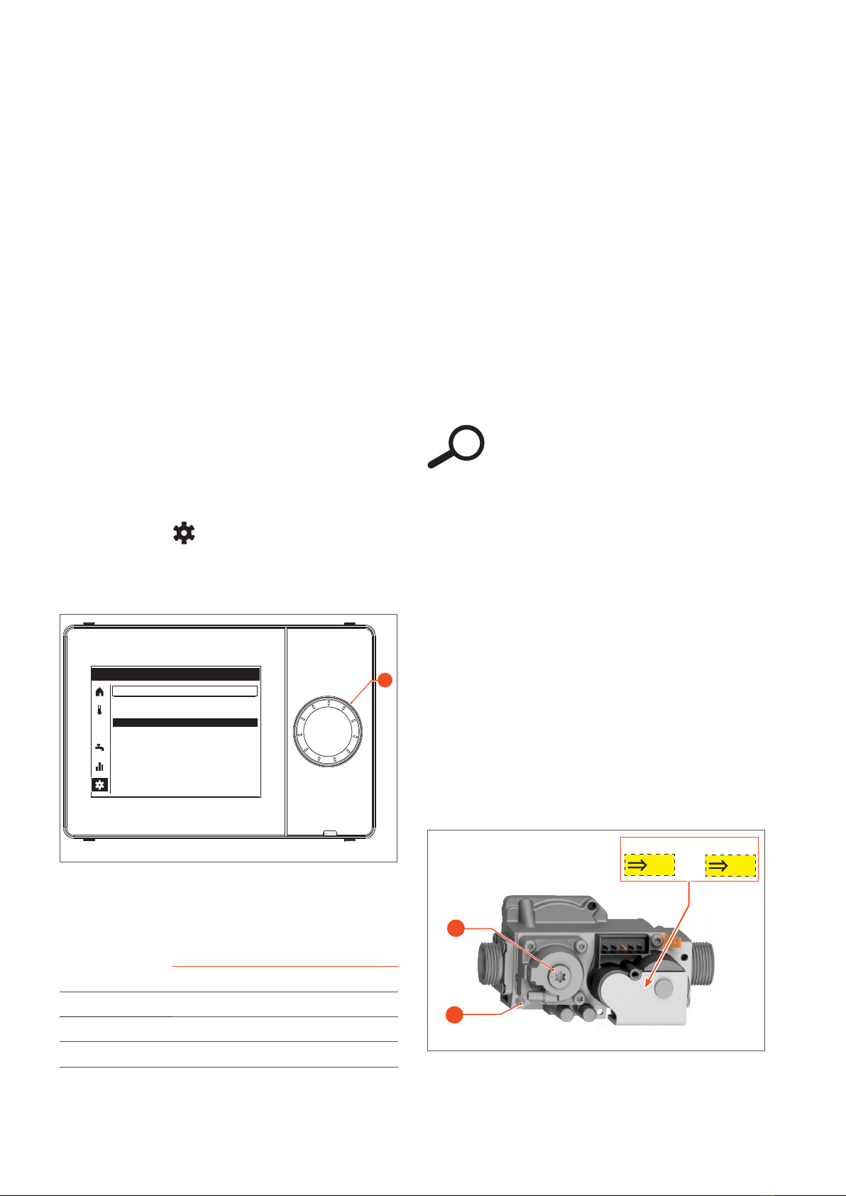
îUsing the rotary selector (1), select and acti-
vate the icon,
îSelect “Special operations (1/3)”,
îSet “Chimney sweep function” to “On”,
îSet “Burner output” to “Full load”.
6. If the value is outside the range, adjust the com-
bustion value by turning the gas valve throttle (2)
in small steps. Allow the value to stabilise before
performing additional adjustments.
- Rotate throttle screw clockwise (to the right)
to decrease the CO2 contents.
- Rotate throttle screw counter-clockwise (to
the left) to increase the CO2 contents.
7. Check CO2 contents in the ue gas at min. output
as follows:
îSet “Burner output” to “Partial load”.
îCheck the CO2 contents, and compare the values
with those in the table at the bottom of the page.
îIf the value is outside the range, adjust the
combustion value by turning the oset screw
(3) in small steps. Allow the value to stabilise
before performing additional adjustments.
The oset screw (3) is factory-sealed.
After adjustment, make sure to reseal it.
8. In “Special operations (1/3)”, set “Chimney
sweep function” to “off”.
9. Press the selector (1) for more than 3 sec. to exit
the setting menu.
10. Restart the boiler to check the ignition behaviour.
Control the correct operation of the boiler by re-
peating steps 1 to 7.
11. Reseal the oset screw (3) using some paint or tape.
Follow-on Task(s):
îOn the gas valve (Fig. 5), place the yellow sticker in-
dicating that a gas conversion has been carried out.
îOn the data plate (back of the boiler), place the white
sticker indicating that a gas conversion has been
carried out.
îReinstall front and top panels, Please refer to the ap-
pliance Installation and Maintenance manual for the
correct procedure.
îRecord the combustion values in the log sheet available
in the installation manual of the appliance.
i
Fig. 4. Combustion Adjustment - Control Panel
3
2
Fig. 5. Combustion Adjustment on Gas Valve
G31
G25/
G25.3
Or
Sticker
27.01.2020 14:42
Special operaons (1/3)
Chimney sweep funcon
On
Back
1
5. Check the CO2 (or O2) contents displayed on the
gas analyser, and compare the values with those in
the table below.
@Min output @Max output
G25 %CO28.4 (±0.1) 8.8 (±0.1)
G31 %CO210.0 (+0.2) 10.5 (+0.2)
G25 %O25.7 (±0.18) 4.9 (±0.18)
G31 %O25.7 (-0.30) 4.9 (-0.30)

This manual suits for next models

1

Other AIC Boiler manuals

AIC NESTA 300 Manual

AIC

AIC NESTA 300 Manual

AIC COILMASTER 100 User manual

AIC

AIC COILMASTER 100 User manual

AIC COILMASTER 100 Manual

AIC

AIC COILMASTER 100 Manual

AIC NESTA PLUS Series Manual

AIC

AIC NESTA PLUS Series Manual

AIC SILOX 140L User guide

AIC

AIC SILOX 140L User guide

AIC Nesta Series Manual

AIC

AIC Nesta Series Manual

AIC NESTA CHROME Series Manual

AIC

AIC NESTA CHROME Series Manual

AIC SILOX S Manual

AIC

AIC SILOX S Manual

AIC NESTA CHROME 24 Manual

AIC

AIC NESTA CHROME 24 Manual

AIC NESTA CHROME 150 Manual

AIC

AIC NESTA CHROME 150 Manual

AIC COILMASTER 70 Manual

AIC

AIC COILMASTER 70 Manual

AIC NESTA CHROME User manual

AIC

AIC NESTA CHROME User manual

AIC COILMASTER 60 User guide

AIC

AIC COILMASTER 60 User guide

AIC NESTA 120 Manual

AIC

AIC NESTA 120 Manual

AIC NESTA CHROME 150 Manual

AIC

AIC NESTA CHROME 150 Manual

Popular Boiler manuals by other brands

HS Flamingo Aquaflam VARIO Series OPERATING AND INSTALLATION Manual

HS Flamingo

HS Flamingo Aquaflam VARIO Series OPERATING AND INSTALLATION Manual

Hamworthy 65he Installation, comissioning and servicing instructions

Hamworthy

Hamworthy 65he Installation, comissioning and servicing instructions

Immergas NIKE MYTHOS 24 4 ERP Instruction and warning book

Immergas

Immergas NIKE MYTHOS 24 4 ERP Instruction and warning book

Watts Aerco Benchmark Series Installation and start-up manual

Watts

Watts Aerco Benchmark Series Installation and start-up manual

Danfoss DWH 200 installation guide

Danfoss

Danfoss DWH 200 installation guide

Immergas MINI NIKE 24 4 ERP Instruction and warning book

Immergas

Immergas MINI NIKE 24 4 ERP Instruction and warning book

Viessmann Vitovalor PT2 E11T Installation and service instructions

Viessmann

Viessmann Vitovalor PT2 E11T Installation and service instructions

Sime SOLO 25 ErP Installer's instructions

Sime

Sime SOLO 25 ErP Installer's instructions

Baxi P-30 Operating, cleaning and maintenance instructions for the user

Baxi

Baxi P-30 Operating, cleaning and maintenance instructions for the user

Velocity PHANTOM II PHTM2200C Installation, operating and service instructions

Velocity

Velocity PHANTOM II PHTM2200C Installation, operating and service instructions

Gorenje TGR 120 NG Instructions for use

Gorenje

Gorenje TGR 120 NG Instructions for use

Bryant BW4 operating instructions

Bryant

Bryant BW4 operating instructions

Navien NFC-175 Installation & operation manual

Navien

Navien NFC-175 Installation & operation manual

Buderus GB142 user manual

Buderus

Buderus GB142 user manual

Unico ELEGANCE GCO-13-00 instruction manual

Unico

Unico ELEGANCE GCO-13-00 instruction manual

Baxi Combi Instant 80 HE Installation & servicing instructions

Baxi

Baxi Combi Instant 80 HE Installation & servicing instructions

Viessmann Vitodens 300 datasheet

Viessmann

Viessmann Vitodens 300 datasheet

Biasi SIGMA CS 32 PV Technical manual

Biasi

Biasi SIGMA CS 32 PV Technical manual

manuals.online logo
manuals.online logoBrands
  • About & Mission
  • Contact us
  • Privacy Policy
  • Terms and Conditions

Copyright 2025 Manuals.Online. All Rights Reserved.