Drehmo c-matic User manual

DREHMOInstruction manual for USB adaptor kit page 1 of 20
DREHMO
Matic C and i–matic
Supplementary instruction manual:
USB-adaptor kit for actuators with integrated control unit
Part number: 187619
Revision: 1.1
Date: 02.03.2018
Remark
This instruction manual has to be kept for further use.

DREHMOInstruction manual for USB adaptor kit page 2 of 20
Table of content:
1General.............................................................................................................................3
1.1 Instructions ................................................................................................................3
1.2 Validity.......................................................................................................................3
1.2.1 Requirements.....................................................................................................3
1.2.2 Delivery content..................................................................................................4
2Driver installation ..............................................................................................................6
2.1 Driver installation under Windows XP........................................................................6
3Connectivity ....................................................................................................................11
3.1 SER01 adaptor........................................................................................................11
3.1.1 Connection on Matic C base plate DMC - 02 (since HW Rev. 5) ..................... 11
3.1.2 Connection on Matic C interface unit DMC - 14 (Profibus DP-V1) ................... 12
3.1.3 Connection on i-matic interface unit DiM - 09 (DeviceNet)............................... 12
3.1.4 Connection on Matic C display unit DMC - 30 (LCD display unit)..................... 13
3.1.5 Connection on i-matic unit DiM - 24 (accumulator unit).................................... 13
3.2 SER02 adaptor........................................................................................................14
3.2.1 Connection on i-matic display unit DiM - 02 (IR / IrII) .......................................14
3.2.2 Connection on i-matic display unit DiM - 22 (Bluetooth)................................... 15
3.3 SER03 adaptor........................................................................................................16
3.3.1 Connection on Matic C base plate DMC - 02 ...................................................17
3.4 SER04 adaptor........................................................................................................18
3.4.1 Connection on i-matic interface unit DiM - 17 (modbus loop)...........................18

DREHMOInstruction manual for USB adaptor kit page 3 of 20
1 General
1.1 Instructions
The following signs draw special attention to safety-relevant procedures in these operation
instructions:
This symbol signifies „additional information“.
Failure to observe may lead to damage occurring.
This symbol signifies „attention“.
Failure to observe may result in damage and personal injury.
This symbol signifies „warning!“
Failure to observe may result in damage and severe personal injury.
SERVICE
Service DREHMO GmbH
fon.: +49 2762 9850-206
fax: +49 2762 9850-210
1.2 Validity
The usage of the described USB adaptor kit is only valid in combination with the DREHMO
specific electrical units as described in detail in the following sections. The adaptors offer a
mean to establish a serial connection between a PC with USB interface and various
intelligent electronic units.
1.2.1 Requirements
The usage of the USB adaptor kit is only allowed for trained staff. The knowledge of basic
electronic and electric rules is required.
A connection setup of the adaptor to the various electronic units is only allowed while
the units are not powered. Safety instructions of the actuator instruction manual and
the available electronic unit documentation have to be observed.

DREHMOInstruction manual for USB adaptor kit page 4 of 20
Serial communication is supported on the PC side by means of separate software. Available
are the software tools i-matic Explorer and Matic C Operator. The corresponding user
manuals have to be observed.
1.2.2 Delivery content
The adaptor kit comprises an USB cable with a DREHMO specific programmed USB-serial
converter and three different adaptor units SER01, SER02, SER03.
A separate adapter cable SER04 for the use in combination with the i-matic modbus loop
interface unit DiM - 17 is furthermore available:

DREHMOInstruction manual for USB adaptor kit page 5 of 20
The following table gives a reference overview for the adapter usage in combination with the
various electronic units.
Adapt
o
r
unit
reference
unit
function
unit
connector
PC
-
Tool
chapter
SER01 DMC - 02.x
from revision 5
Matic C
base plate
X11
(lower side)
Matic C
Operator
3.1.1
DMC - 14 Matic C
profibus DP-V1
TEST Matic C
Operator
3.1.2
DiM - 09 i-matic
DeviceNet
X2, X3 WinGate
1
3.1.3
DMC - 30 Matic C
LCD display unit
CN1 Flash
Magic2
3.1.4
DiM - 24 i-matic
accumulator unit
CN1 Flash
Magic2
3.1.5
SER02 DiM - 02 i-matic
display unit IR / IrII
X2 i-matic
Explorer
3.2.1
DiM - 22 i-matic
display unit
Bluetooth
X2 i-matic
Explorer
3.2.2
SER03 DMC - 02.x
all revisions
Matic C
base plate
X6
(upper side)
Matic C
Operator
3.3.1
SER04 DiM - 17 i-matic
modbus loop unit
XT i-matic
Explorer
3.4.1
Remark:
A connection to the units DiM – 09, DMC – 30 and DiM – 24 is only allowed for
especially trained staff. The usage of the given tools by strictly following the
instruction manuals of the electronic units is required. Otherwise, the intended
function of the units may be disturbed.
1 WinGate - Tool of company Deutschmann Automation
2Flash Magic – Tool of Embedded Systems Academy / Philips Semiconductors

DREHMOInstruction manual for USB adaptor kit page 6 of 20
2 Driver installation
2.1 Driver installation under Windows XP
The usage of the adaptors by means of a PC with operating system Windows XP requires
the installation of DREHMO specific drivers. These drivers can be downloaded from the
companys web site www.drehmo.com.
This chapter shows the user of the adaptor kit how the installation procedure of the required
drivers are done under the operation system Windows XP
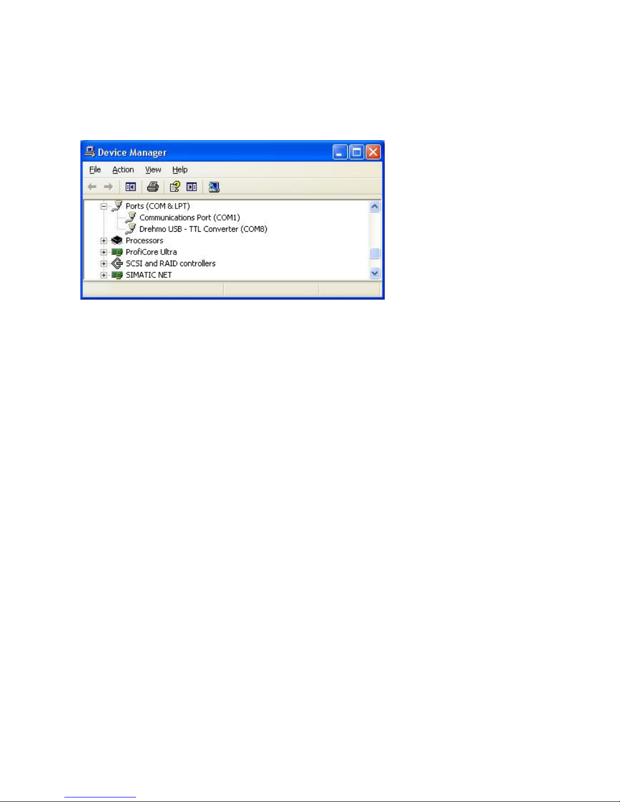
The device simulates a virtual communication port under Windows over which the device is
accessed by the service tools. To install the needed drivers please follow the instructions in
the respective section below.
System requirements
Software:
Windows XP SP2
Hardware (recommended):
Min. 700MHz CPU
Min. 128MB RAM
Download the latest available drivers from the Drehmo website www.drehmo.com and unzip
them to a location on your PC.
If you are running Windows XP or Windows XP SP1, temporarily disconnect your PC from
the Internet. This can be done by either removing the network cable from your PC or by
disabling your network card by going to the "Control Panel\Network and Dial-Up
Connections", right clicking on the appropriate connection and selecting "Disable" from the
menu. The connection can be re-enabled after the installation is complete. This is not
necessary under Windows XP SP2 if configured to ask before connecting to Windows
Update. Windows XP SP2 can have the settings for Windows Update changed through
"Control Panel\System" then select the "Hardware" tab and click "Windows Update".
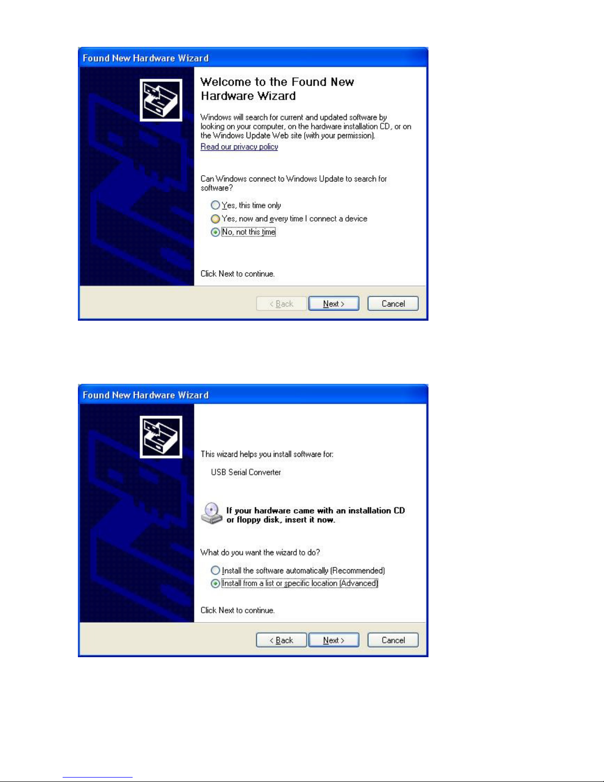
Connect the device to a spare USB port on your PC. This will launch the Windows “Found
New Hardware Wizard”. If there is no Internet connection available or Windows XP SP2 is
configured to ask before connecting to Windows Update, the screen below is shown. Select
"No, not this time" from the options available and then click "Next" to proceed with the
installation. If there is an Internet connection available, Windows XP will silently connect to
the Windows Update website and install any suitable driver it finds for the device in
preference to the driver manually selected.

DREHMOInstruction manual for USB adaptor kit page 7 of 20
Select "Install from a list or specific location (Advanced)" as shown below and then click
"Next".

DREHMOInstruction manual for USB adaptor kit page 8 of 20
Select "Search for the best driver in these locations" and enter the file path in the combo-box
("C:\TEMP\DREHMO_Driver_V2_06_00" in the example below) or browse to it by clicking the
browse button. Once the file path has been entered in the box, click next to proceed.
If Windows XP is configured to warn when unsigned (non-WHQL certified) drivers are about
to be installed, the following screen will be displayed. Click on "Continue Anyway" to continue
with the installation. If Windows XP is configured to ignore file signature warnings, no
message will appear.

DREHMOInstruction manual for USB adaptor kit page 9 of 20
The following screen will be displayed as Windows XP copies the required driver files.
Windows should then display a message indicating that the installation was successful. Click
"Finish" to complete the installation. The serial converter driver is now installed. In order to
enable the Drehmo components to communicate with the converter the COM port emulation
driver must be installed.

DREHMOInstruction manual for USB adaptor kit page 10 of 20
After clicking "Finish", the Found New Hardware Wizard will continue by installing the COM
port emulation driver. The procedure is the same as that above for installing the serial
converter driver.
Open the Device Manager (located in "Control Panel\System" then select the "Hardware" tab
and click "Device Manger") and select "View > Devices by Type". The device appears as an
additional COM port with the label "Drehmo USB – TTL Converter".

DREHMOInstruction manual for USB adaptor kit page 11 of 20
3 Connectivity
3.1 SER01 adaptor
The SER01 adaptor enables the access by means of a 5 pole female reverse polarity
protected connector. By means of an integrated push button, a reset of the attached
electronic unit can be forced.
3.1.1 Connection on Matic C base plate DMC - 02 (since HW Rev. 5)
The following pictures show the position of the interface connector for the SER01 adaptor on
the DMC - 02 unit - available for hardware revision 5 or higher.
Attention:
In case of a mounted DMC - 14 unit (Profibus DP-V1 interface) the usage of this connection
is restricted. The direct serial access to the base board requires in any case the dismount of
the interface unit DMC - 14.

DREHMOInstruction manual for USB adaptor kit page 12 of 20
3.1.2 Connection on Matic C interface unit DMC - 14 (Profibus DP-V1)
The following picture shows the position of the interface connector for the SER01 adaptor on
the DMC - 14 unit.
3.1.3 Connection on i-matic interface unit DiM - 09 (DeviceNet)
The following picture shows the position of the interface connector for the SER01 adaptor on
the DiM - 09 unit. In case of redundancy, two connectors are available (one for each
channel).

DREHMOInstruction manual for USB adaptor kit page 13 of 20
3.1.4 Connection on Matic C display unit DMC - 30 (LCD display unit)
The following pictures show the position of the interface connector for the SER01 adaptor on
the DMC - 30 unit.
3.1.5 Connection on i-matic unit DiM - 24 (accumulator unit)
The following pictures show the position of the interface connector for the SER01 adaptor on
the DiM - 24 unit.

DREHMOInstruction manual for USB adaptor kit page 14 of 20
3.2 SER02 adaptor
The SER02 adaptor enables the serial access by means of a 4 pole female socket connector
matching on a corresponding 4 pole pin connector in 2,54mm pitch. Reverse polarity
protection is given by means of the special outline geometry of the adaptor board itself.
3.2.1 Connection on i-matic display unit DiM - 02 (IR / IrII)
The following picture shows the position of the interface connector for the SER02 adaptor on
the DiM - 02 unit.
The correct plug in polarity of the adaptor is only given, if the expanded finger like
board outline fits aside the display board edge.

DREHMOInstruction manual for USB adaptor kit page 15 of 20
3.2.2 Connection on i-matic display unit DiM - 22 (Bluetooth)
The following picture shows the position of the interface connector for the SER02 adaptor on
the DiM - 22 unit.
The position of the 4 pole pin connector is located in a horizontal position underneath
the mounted LCD panel on the electronic board edge. The expanded finger like
adapter outline protects against an unintended reverse polarity. The adaptor has to be
easily plugged in with a plug in depth of about 6mm.

DREHMOInstruction manual for USB adaptor kit page 16 of 20
3.3 SER03 adaptor
The SER03 adaptor enables the serial access by means of a 2x6 pole male pin connector
matching on a corresponding 2x6 pole female socket connector in 2,54mm pitch.
Reverse polarity protection is not given by the design. The detection of the correct
polarity is only possible by means of the matching labeling J8, J9, X6 which can be
found on the adaptor as well as on the base board print.
A mismatch of polarity may result in a defect of the adaptor and the base plate!

DREHMOInstruction manual for USB adaptor kit page 17 of 20
3.3.1 Connection on Matic C base plate DMC - 02
The following picture shows the position of the interface connector for the SER03 adaptor on
the DMC - 02 unit in version DMC – 02.7.
The adaptor has to be connected as shown in the following pictures for DMC – 02.8

DREHMOInstruction manual for USB adaptor kit page 18 of 20
3.4 SER04 adaptor
The SER04 adaptor enables serial access by means of a 10 pole female reverse polarity
protected connector. By means of an integrated push button, a reset of the attached
electronic unit can be forced. Two DIL-switches S1 and S2 are available for different
configuration of functionality. The settings of these switches are explained in detail in the
documentation of the connected electronic.
3.4.1 Connection on i-matic interface unit DiM - 17 (modbus loop)
The following picture shows the position of the interface connector for the SER04 adaptor on
the DiM - 17 unit.

DREHMOInstruction manual for USB adaptor kit page 19 of 20

DREHMOInstruction manual for USB adaptor kit page 20 of 20
Product range of electric actuators with integrated control unit
Actuators of type Actuators of type
Matic C: i-matic:
Multiturn actuators DMC30-DMC1000 Multiturn actuators DiM30-DiM1000
max. 1000 Nm max. 1000 Nm
Part-turn actuators DPMC30-DPMC1599 Part-turn actuators DPiM30-DPiM1599
max. 1600 Nm max. 1600 Nm
Linear actuators DMC15-DMC80 Linear actuators DLiM15-DLiM80
max. 80 kN max. 80 kN
Additional gear available:
worm gear
bevel gear
spur gear
DREHMO GmbH
Zum Eichstruck 10
57482 Wenden / Germany
Tel.: +49 2762 9850-206
Fax: +49 2762 9850-210
Internet: www.drehmo.com
Other manuals for c-matic
1
This manual suits for next models
1
Table of contents