DROPSA 0086450 Operating instructions

Hydraulic inverter
User and
maintenance manual
Original instructions
C2247IE WK 27/15
TABLE OF CONTENTS
1. INTRODUCTION
2. GENERAL DESCRIPTION
3. PRODUCT IDENTIFICATION
4. TECHNICAL CHARACTERISTICS
5. COMPONENTS
6. UNPACKING AND INSTALLING
7. OPERATING INSTRUCTIONS
8. TROUBLESHOOTING
9. MAINTENANCE PROCEDURE
10. DISPOSAL
11. ORDERING INFORMATION
12. DIMENSIONS
13. HANDLING AND TRANSPORTATION
14. OPERATING HAZARDS
15. PRECAUTIONS
http://www.dropsa.com
Via Benedetto Croce, 1
Vimodrone, MILANO (IT)
t. +39 02 250791
Dropsa products can be purchased from Dropsa branches and authorized distributors, visit

2
1. INTRODUCTION
This User and Maintenance Manual refer to Dropsa’s “hydraulic inverter with three pistons “.
You can find additional copies and newer revisions of this document from our website http://www.dropsa.com.
Alternatively contact one of our Sales Offices.
This manual contains important information on health and safety issues the personnel. It is recommended to attentively read
this manual and carefully keep it in good condition so that it is always available to personnel requiring to consult it.
2. GENERAL DESCRIPTION
Hydraulic inverter has been designed to control the dual line system supply (02 System ), it is able to work both with oil and
grease at 5880 psi (400 bar) max pressure.
The function of this Hydraulic inverter is that both main lines have to be alternately pressurized and be relieved of pressure.
3. PRODUCT IDENTIFICATION
Machine identification label is located on the front side of the reservoir and
contains product serial number, input voltage and details of the operating
parameters.
4. TECHNICAL CHARACTERISTICS
GENERAL CHARACTERISTICS
Weight
4.5 Kg
HYDRAULIC CHARACTERISTICS
Max flow rate
400 cc/min
Max working pressure
300 bar
Outlet and inlet connection
G3/8” BSP
Adjustment range
60÷300 bar
Temperature of use
- 5 + 50 C (23° ÷ +122° F)
Humidity
90 % Rel. humidity
Lubricants
Max greaseNLGI2
Min oil 100 cSt
Storage temperature
-20 +65 °C
N.b. The specifications refer to the temperature of use of +20°C (+68°F)
* If a different product is used, please contact Dropsa S.p.A. to ensure it is suitable for use

3
4.1 Hydraulic system
Exchange line 2->1 (fig.4) - when fluid attains the adjusting spring pressure
calibration "PS1", the pilot conduit opens causing the displacement of the
chamber from the position "a" to the position "b"
Activation line 2 (fig.3) - with valve in position "b" the pump pushes lubricant to
line 2. Line 1 is discharge phase.
Exchange line 1->2 (fig.2) - when fluid reaches the adjusting spring pressure
calibration "PS1", the pilot conduit opens causing the displacement of the
chamber from the position "b" to the position "a"
Activation line 1 (fig.1) - with valve in position "a" the pump pushes lubricant
to line 1. Line 2 is discharge phase.
Fig.1
Fig.2
Fig.3
Fig.4

4
5. COMPONENTS
6. UNPACKING AND INSTALLATION
6.1 UNPACKING
Once a suitable installation position has been identified, unpack the product and prepare for installation. It is important to
inspect the product to ensure that there has been no damage during transportation. The packaging material used does not
require any special disposal procedures. You should refer to you regional requirements.
6.2 Installing
1. Fixing the valve on the pump using four M10 screws supplied, tightening with a torque of 35 Nm. Pay attention at the
correct positioning of ORings.
2. Connect two outlet pipes to G3 /8" holes marked 1 and 2 on the adapter plate.
7. OPERATING INSTRUCTIONS
7.1 Start-up
Before using the product, a few preliminary checks must be performed:
Check Modular directional valve integrity;
Check that the valve is at running temperature and
that the pipes are free of air pockets
Check that the electrical connection has been carried
out correctly;
Check that there aren’t lubricant leakage or air
pressure loss;
Check that the lock screws are properly screwed up;
Use gloves and safety goggles, as stipulated in the
safety chart for the lubricating oil;
DO NOT use lubricants that may irritate the NBR
gaskets; if in doubt, contact the Dropsa SpA technical
office, which can provide you with a detailed chart of
recommended oils;
Not ignore dangers to the health and maintain the
regular hygiene standard.
VALVE COMPONENTS
1
Adapter plate for SUMO/MINISUMO
2
Pressure adjustment
1
35Nm
2
Line 2
Line 1
Pump
Return
P
R
1
2

5
8. PROBLEMS AND SOLUTIONS
TROUBLESHOOTING TABLE
PROBLEM
POSSIBLE CAUSE
REMEDIAL ACTION
The modular valve
doesn’t invert
Piston jammed
Verify correct sliding of piston
Possible replacement valve
The modular valve has reached the maximum
pressure level
Adjust the pressure to a maximum of 400 bar (5880 psi)
Important lubricant leakage from one of the four
connection pipes
Verify piping status and the connections to fittings.
Replace worn out pipelines
Gasket broken
Replace
Valve leaks
lubricant
Breaking of internal gaskets
Replace
: Operations by specialized Dropsa personnel (ship the product to Dropsa headquarters)
9. MAINTENANCE PROCEDURE
The product does not necessitate any special tool for operation and maintenance. When working with the pump it is
nonetheless recommended that personal health and safety equipment is used as is normal for any operation in an industrial or
similar workplace.
The pump has been designed and built as to require minimal maintenance and operate in different and challenging operating
environment. It is recommend that the unit is inspected and kept clean to ensure long life and trouble free operation. It is
important to check all tubing on the system to ensure that it is always tight and leak free.
ITEM
FREQUENCY
OPERATION
Integrity of tubing and system
After initial 500 hours.
Every1500 hours.
Check fittings and tubing secured.
Verify components are correctly fixed to machine.
In any doubts and/or problematic not solved, do not proceed to search by removing machine parts but contact our technical office
10. DISPOSAL
During maintenance or disposal of the machine care should be taken to properly dispose of environmentally sensitive items such
as oils or other lubricants. Refer to local regulations in force in your area. When disposing of this unit, it is important to ensure
that the identification label and all the other relative documents are also destroyed.
WARNING: Before carrying out any maintenance operation, ensure that power and hydraulic system are
disconnected.

6
11. ORDERING INFORMATION
11.1. 4/3 Direction valve
Description
Part Number
Hydraulic inverter
0086450
11.2. Optional
Description
Part Number
Pressure gauge Kit
3133910
Ultrasensor
1655305
M12 female connector
0039999
M12 female connector +cable L 5 mt
0039815
11.2. Spare parts
Description
Part Number
OR gasket valve/pump
3190500
Right pressure gauge
3292172
Left pressure gauge
3292171
Positioning pressure gauge
(optional)
Positioning Ultrasensor
(optional)

7
WARNING: It is necessary to carefully read about the instructions and the risks involved in the use of lubrication
machines. The operator must know the machine functioning through the User and Maintenance Manual.
12. DIMENSIONS
Dimensions in mm [in].
13. HANDLING AND TRANSPORT
Before shipping, the units are carefully packed inside cardboard boxes. When transporting and storing the equipment, pay
attention to the direction indicated on the boxes themselves.
Upon receipt, check that the package has not been damaged and store the equipment in a dry location.
14. OPERATING HAZARDS
Flammability
The lubricant generally used in lubrication systems is not normally flammable. However, it is advised to avoid contact with
extremely hot substances or naked flames.
Pressure
Before each operation, make sure there in every branch of the lubrication circuit that there is no residual pressure that could
cause oil to spray when disassembling fittings or components.
Noise
Under normal operating conditions, noise emission does not exceed 70 dB “A”.

8
14.1 LUBRICANTS
A comparison table is provided between the classification of NLGI lubricants (National
Lubricating Grease Institute) and the ASTM classification (American Society for Testing and
Materials) for greases for the values that concern the product.
For further information about the technical specifications and the safety measures to adopt,
refer to the product safety sheet (Directive 93/112/EEC) relative to the type of lubricant
selected and supplied by the manufacturer.
15. PRECAUTION
Compliance with the essential safety requirements and the provisions specified in the machine directive was checked by filling
out prepared check lists that are contained in the technical file.
Three types of lists were used:
Risk assessment (UNI EN ISO 14121-1).
Compliance with the essential safety requirements Machine Directive –EC 06/42).
Electrical safety requirements (EN 60204-1).
The following is a list of dangers which have not been fully eliminated but which are considered acceptable:
During installation there may be small low pressure oil seepage from the pump. Always use appropriate protective
clothing, gloves and take all necessary safety precautions.
Contact with lubricant during maintenance or filling of the reservoir. As per previous point, correct precautions must be
taken to protect from contact with lubricant.
Electric shock. All electrical connections must be carried out by a qualified electrician who has studied the connection
to ensure no electrical danger
Unsuitable Lubricant. Lubricant characteristics are indicated on the pump and in this user manual. In any case contact a
Dropsa Sales and Support engineer (if in any doubts, contact the Technical Department Dropsa SpA).
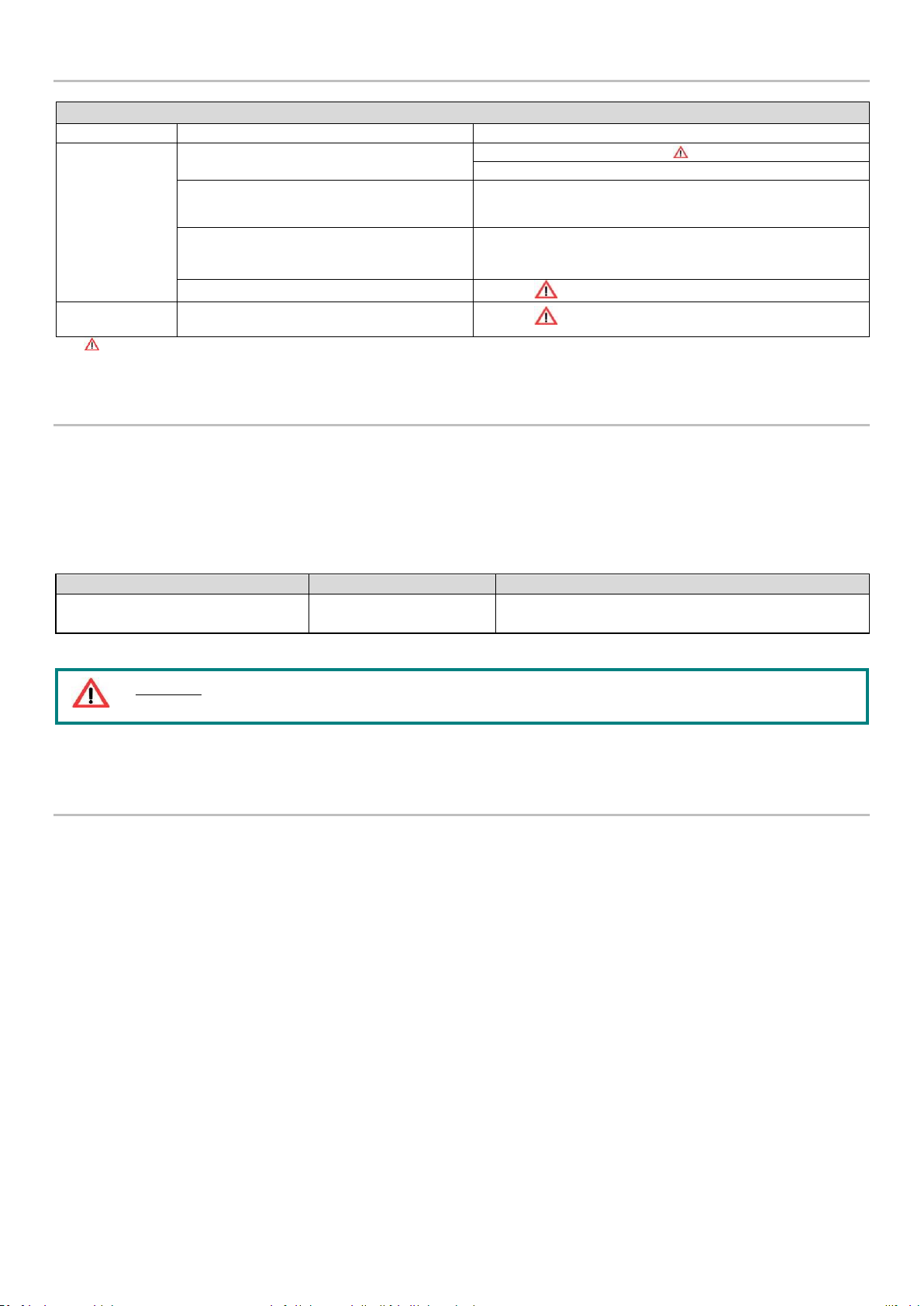
FLUIDS EXPLICITY NOT ALLOWED
Fluid
Dangers
Lubricants with abrasive additives
Wear of the components inside the pump
Lubricants with silicone based additives
Pump seizure
Petrol –solvents –inflammable liquids
Fire –explosion –damage to the gaskets
Corrosive products
Pump corrosion - damage to people
Water
Pump oxidation
Food substances
They would be contaminated
GREASES
NLGI
ASTM
00
400 –430
0
355 –385
1
310 –340
2
265 –295
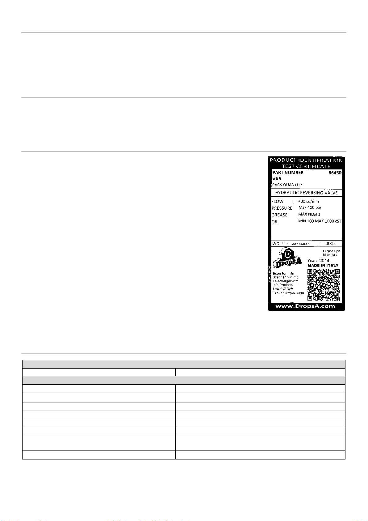
NOTE: The pump is designed to operate with maximum NLGI 2 grade lubricants.
Use lubricants compatible with NBR gasket
The residual lubricant used for assembly and testing is NLGI 2 grade.
Table of contents
Popular Inverter manuals by other brands

Kensington
Kensington 33362 reference guide

SMA
SMA SUNNY ISLAND 4.4M Replacement of Various Components

U.S. Solar Mounts
U.S. Solar Mounts 30 Series installation manual

Schweißkraft
Schweißkraft CRAFT-STICK 141 operating instructions

Xantrex
Xantrex FREEDOM HW 1000 installation guide

A2Z Ozone
A2Z Ozone MP-3000 operating manual