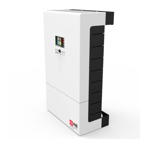
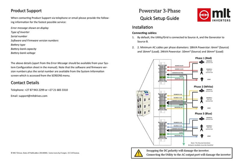
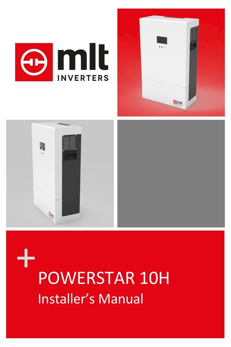
MLT Inverters POWERSTAR 10 User manual

+
POWERSTAR 10
Three Phase Quickstart Guide

PAGE 1
© 2019 MLT Inverters
PS10-APP01 - Powerstar 10H - Three Phase Quickstart Guide - v0.02

PAGE 2 PS10-APP01 – V0.02 – 2019/09/11
Powerstar 10H – Application Note Series
Table of Contents
1. Introduction .......................................................................................................................... 4
1.1 Warnings and Cautions ................................................................................................ 4
1.2 Contacting MLT Inverters ............................................................................................ 5
1.2.1 Product Support................................................................................................... 5
1.2.2 Contact Details ..................................................................................................... 5
1.2.3 Telephone ............................................................................................................ 5
2. Scope ..................................................................................................................................... 6
3. Overview ............................................................................................................................... 6
4. Startup instructions .............................................................................................................. 6
4.1 General Instructions ..................................................................................................... 6
4.1.1 Three Phase Specific Instructions ....................................................................... 7
5. An overview of the Inverter’s Human Machine Interface System.................................. 10
5.1 The Touch Screen Display .......................................................................................... 10
5.1.1 The Dashboard Screen ...................................................................................... 10
5.1.2 The Control Screen ............................................................................................ 11
5.1.3 The History Screen ............................................................................................. 12
5.1.4 The Settings Screen ........................................................................................... 12
5.2 Buttons and Switches ................................................................................................. 13
5.2.1 The On/Off Switch ............................................................................................. 13
5.2.2 The Start/Stop (and Fault Reset) Button .......................................................... 13
5.3 The Status LED Indicators .......................................................................................... 13
5.3.1 The AC Source LED ............................................................................................. 14
5.3.2 The Inverter LED ................................................................................................ 14
5.3.3 The Battery LED ................................................................................................. 15

PAGE 3
Figures
Figure 1. A typical layout of a single-phase Powerstar 10H installation showing the inverter (7), the
battery bank (10), the battery cable fuse box (9), the AC Bypass Box (3), and an optional MPPT.
For the most part, the user will interact with the inverter using the inverter’s touch screen display.
7
Figure 2. A screenshot of the inverter’s touch screen display or Human Machine Interface (HMI). From
top to bottom the buttons on the right side navigate between the dashboard panel, the control
panel, the charts and events panel, and the settings panel, respectively. .......................... 8
Figure 3. To start/stop the inverter using the touch-screen display, navigate to the control panel and
then click the ‘turn on’/’turn off’ button. (Note: The inverter must be in Standby mode before it
will start, as explained in the text.) ........................................................................................ 9
Figure 4. This figure shows the underside of the enclosure where the on/off switch, the start/stop
button, the ethernet port, and the entry points for the AC and DC power cables are located.
9
Figure 5. An image showing the position of the Powerstar 10H’s touch screen display, the status LEDs,
the start/stop button and the on/off switch. ...................................................................... 10
Figure 6. The top-level settings screen. ........................................................................................ 12
Figure 7. The icons used with the status LEDs. From left to right, the LEDs indicate the status of the AC
Source (e.g. Mains), the inverter, and the battery. ............................................................. 13

PAGE 4 PS10-APP01 – V0.02 – 2019/09/11
1. Introduction
1.1 Warnings and Cautions
A safety instruction (message) includes a hazard alert symbol and a signal word, WARNING or
CAUTION. Each signal word has the following meaning:
HIGH VOLTAGE: This symbol indicates the presence of a high voltage. It calls your
attention to items or operations that could be dangerous to yourself or others
operating this equipment. Read the message and follow the instructions carefully.
WARNING: Indicates a potentially hazardous situation which, if not avoided, can result
in serious injury or death.
CAUTION: Indicates a potentially hazardous situation which, if not avoided, can result
in minor to moderate injury, or serious damage to the product. The situation
described in the CAUTION may, if not avoided, lead to serious results.
GENERAL WARNINGS
DANGER OF ELECTRIC SHOCK. There are no user serviceable parts inside the inverter. DO NOT attempt to make
repairs or alterations to the unit.
WARNING: This equipment should be installed, adjusted, and serviced by qualified electrical maintenance
personnel familiar with the construction and operation of the equipment and the hazards involved. Failure to
observe this precaution could result in personal injury.
GENERAL CAUTIONS
CAUTION: Always wear personal protective equipment (protective clothing, gloves, and safety boots) while
performing an installation or maintenance, to avoid the danger of injuries.
CAUTION: Proper grounds, disconnecting devices, e.g. bypass boxes and other safety devices and their location
are the responsibility of the user and are not provided by MLT Inverters.
CAUTION: Do not cover the device or store it in a small space - always keep it well ventilated and well away from
flammable gases or powders. Components in the device could potentially cause a small electric spark that could
ignite flammable gas or powders. Flammable gases are created by batteries and can become a hazard in poorly
ventilated spaces.
CAUTION: For indoor use only and MUST be installed in a dry area free from conductive liquids or conductive
debris. If part of the inverter becomes submerged in water look for a safe way to isolate it at the distribution
board and if possible at the batteries.

PAGE 5
1.2 Contacting MLT Inverters
1.2.1 Product Support
When contacting Product Support via telephone, email or fax please provide the following information
for the fastest possible service:
Type of Inverter
Serial number
Battery type
Battery bank capacity
Battery bank voltage
A description of the event
Note that the serial number is available on the serial plate that is attached to the bottom of the machine
inside the cover.
1.2.2 Contact Details
Telephone: +27 (0) 21 201 1335
Email: info@mltinverters.com
Address: 103 Garfield Road
Kenilworth 7708
Cape Town
South Africa
1.2.3 Telephone
You can reach technical support by telephone directly Monday to Friday between 08h00 and 17h00
(GMT +2 hours). Queries outside of these hours should be directed to support@mltinverters.com and
will be answered at the earliest opportunity. When contacting technical support, please ensure that
you have the information listed above available.

PAGE 6 PS10-APP01 – V0.02 – 2019/09/11
2. Scope
This quickstart guide is intended for the end user. It gives a brief guide on how to start and stop the
inverter and how to reset any temporary faults.
3. Overview
The Powerstar 10H inverter/charger offers a cost-effective and reliable solution to the home or farm
owner faced with unreliable or no grid electricity supply. Each Powerstar unit in a system can deliver
10 kW for half-an-hour and 8 kW continuously.
The inverter operates at low-voltage DC and is transformer-based, which translates to a robust and
safe product that guarantees trusted power in the harshest environments. A typical installation will
include the inverter/charger, a battery bank, a battery cable fuse box (9), and an AC Bypass Box (3). The
installation often also includes either some dc-coupled solar chargers or ac-coupled solar grid-tied
inverters. An example of such a system is shown in Figure 1.
The Powerstar inverter system can be configured in various ways, one of these is with 3 units running
as a three phase off-grid generator.
This document describes how to start and stop a single-phase system, and subsequently a three-phase
system.
4. Startup instructions
4.1 General Instructions
One will normally startup/stop the inverter using its touch screen display (referred to here as the
Human Machine Interface or HMI for short). The HMI is on the front of the inverter as shown in Figure
1. Every screen on the HMI includes the navigation bar on the right side. From top to bottom, the
navigation bar is used to navigate between the dashboard panel, the control panel, the charts and
events panel, and the settings panel (Figure 2).
Assuming that the machine is ready to startup, i.e. it is in Standby mode, navigate to the control screen
by clicking on the standby symbol (second icon from the top right). Once on the control panel, click on
the “Turn On/Turn Off” icon which will be on the left of the screen (see Figure 3). The inverter will go
into Startup mode, and then shortly afterwards Stand-Alone mode. (Note the inverter’s operational
mode is given in the status bar which is shown at the bottom of the dashboard and control screens).
Once the inverter is running in Stand-Alone mode it will be powering the loads on its load port but will
not be connected to the mains supply on the source port. If the mains supply is available, the inverter
will synchronise to it and after 60 seconds connect to it and go into Grid Tied mode.

PAGE 7
4.1.1 Three Phase Specific Instructions
NOTE: For a three-phase system, one machine must be setup as the Master machine and it should be
assigned to phase 1. The other machines should be assigned to phase 2 and 3 to match the phase
rotation of the grid installation. The installer should setup this up before they start up the machines for
the first time.
With all relevant settings set, starting up a three-phase system is similar to that of starting up a single
machine. Firstly, the on/off switch on all the inverters must be in the on position. Then with all
machines in Standby mode, the machines can be started up using the instructions from the previous
section. The start instruction can be given on any one of the machines. The Master machine will then
check the communication and synchronization between the machines after which the machines will
start-up altogether in Stand-Alone Mode. Similarly, the stop command can be given on any one of the
machines.
Figure 1. A typical layout of a single-phase Powerstar 10H installation showing the inverter (7), the
battery bank (10), the battery cable fuse box (9), the AC Bypass Box (3), and an optional MPPT. For the
most part, the user will interact with the inverter using the inverter’s touch screen display.

PAGE 8 PS10-APP01 – V0.02 – 2019/09/11
The instructions just given assume that the inverter is in Standby mode and ready to start. If this is not
the case, then:
check that the “On/Off Switch” on the underside of the inverter is in the “On” position (see
Figure 4),
reset any faults by navigating to the control panel and clicking the reset icon.
If for some reason the inverter does not start, then contact your installer or continue reading this
manual.
Figure 2. A screenshot of the inverter’s touch screen display or Human Machine Interface (HMI). From
top to bottom the buttons on the right side navigate between the dashboard panel, the control panel,
the charts and events panel, and the settings panel, respectively.

PAGE 9
Figure 3. To start/stop the inverter using the touch-screen display, navigate to the control panel and
then click the ‘turn on’/’turn off’ button. (Note: The inverter must be in Standby mode before it will
start, as explained in the text.)
Figure 4. This figure shows the underside of the enclosure where the on/off switch, the start/stop
button, the ethernet port, and the entry points for the AC and DC power cables are located.
On/Off Switch
Start/Stop Button
Ethernet Port
AC Load
AC Supply
Bat +
Bat -

PAGE 10 PS10-APP01 – V0.02 – 2019/09/11
5. An overview of the Inverter’s Human Machine Interface System
The Powerstar 10H includes a touch screen display, three status LEDs, an on/off switch, a start/stop
button, and an ethernet port for web-based monitoring/control. Together these make up the Human
Machine Interface system.
5.1 The Touch Screen Display
As shown in Figure 5, the Powerstar 10H has a touch screen display on its front. The touch screen
display is often referred to as the Human Machine Interface (HMI) in MLT documents as it is the primary
way the user will interact with the machine.
The touch screen display’s user interface consists of four main screens, namely the: dashboard screen,
the control screen, the history (or charts and events) screen, and the settings screen.
Figure 5. An image showing the position of the Powerstar 10H’s touch screen display, the status LEDs,
the start/stop button and the on/off switch.
5.1.1 The Dashboard Screen
An example of how the dashboard screen might look is shown in Figure 2. The dashboard screen
includes a status bar shown on the bottom of the screen. In the status bar, the inverter’s operational
mode is shown and underneath this any recent events or messages. The status bar also shows the time
and date as set on the inverter.
The dashboard also shows a collection of icons which can show how power is flowing through the
system or alternatively the voltage and currents measured at various points in the system. To cycle

PAGE 11
between showing power flow (i.e. kW or kVA) and/or voltage (V) or current (Amps) click on the purple
units icon.
The description of each of the icons is given in Table 1.
Table 1. A table describing the icons shown on the dashboard screen of the
touch screen display.
Icon Position (Colour) Description
Top Left (Red) Power (kW), voltage (V), or current (Amps) as measured at the
inverter’s SOURCE PORT.
Top Middle (Blue) The Inverter.
Top Right (Orange) Power (kW), voltage (V), or current (Amps) as measured at the
inverter’s LOAD PORT.
Bottom Left (Blue) Power (kW) or current (Amps) generated by the solar system.
Bottom Middle (Green) Power (kW), voltage (V), or current (Amps) as measured at the
inverter’s BATTERY PORT.
5.1.2 The Control Screen
5.1.2.1 Starting or Stopping the Inverter
An example of how the control screen might look is shown in Figure 3. The control screen includes two
icons, namely a “turn on/turn off” icon and a “reset” icon and a status bar which shows the inverter’s
operational mode and any recent events/messages. The “turn on/turn off” icon is used to start or stop
the inverter. (Note, the inverter can only be started using this icon if the “On/Off” switch is in the “On”
position, as already described.)
5.1.2.2 Resetting Faults and Warnings
If the inverter’s controller has detected some fault which will prevent it from starting then the icon on
the left will not show a tick, a relevant message will be shown in the status bar, and the Inverter Status
LED (described later) will not be green. Many of the faults the controller detects can be remedied easily
(for example the communication cable between the inverter and the battery bank was unplugged). If
you believe the fault has been remedied, then click on the “Reset” icon. If the fault is still present the
controller will detect it again, otherwise the inverter will go into Standby mode (assuming the “On/Off”
switch is in the correct position).
If the fault persists then contact your intsaller.

PAGE 12 PS10-APP01 – V0.02 – 2019/09/11
5.1.3 The History Screen
Clicking on the third icon from the top in the navigation pane will take the user to the History (Charts
and Events) screens. On this screen, the user can cycle between sub-screens. Namely:
a plot of the power measured at the inverter’s source port over the last 24 hours,
a plot of the power measured at the inverter’s load port over the last 24 hours,
the battery State of Charge (SoC) or voltage measured over the last 24 hours, and
the list of recent events/messages.
5.1.4 The Settings Screen
The Settings Screen is shown in Figure 6. There are a few icons which will take the user to settings
wizards that show a collection of commonly used and related settings, for example the “battery setup”
wizard. The advanced icon allows the user/installer to access all the user settings as well as real-time
data points. Many of the settings are passcode protected to prevent the user from changing them
unintentionally.
If you feel that you need to change a setting, then contact your installer for assistance.
Figure 6. The top-level settings screen.

PAGE 13
5.2 Buttons and Switches
The Powerstar has an on/off switch and a start/stop push button on the underside of the enclosure as
shown in Figure 4.
5.2.1 The On/Off Switch
When this switch is in the off position the inverter will stay in System Off mode and will not respond to
start/stop instructions. When the switch is in the on position, the inverter will go into Standby mode
and will respond to start/stop instructions.
5.2.2 The Start/Stop (and Fault Reset) Button
On the underside of the inverter, there is a start/stop push button located next to the on/off switch
(Figure 4). This button also acts a fault reset button. This button has a few functions depending on the
operating mode of the inverter and for how long the button is pushed:
If the inverter is running and the button is pushed the inverter will stop running and return
to Standby mode;
If the inverter is Tripped, Off, or in Standby mode and the button is pushed any faults will be
reset; and
If the inverter is in Standby mode and the button is pressed in for 3 seconds or more the
inverter will go into Full Auto mode, i.e. the inverter will start up into Stand-Alone mode. On
a single machine setup, if the grid is available the machine will synchronise and then connect
to the grid.
5.3 The Status LED Indicators
On the front of the inverter, underneath the touch screen display, there are three status LEDs that can
flash green, orange, and/or red. There is a status LED for the AC source, the inverter, and the battery.
The icons used to label the LEDs are shown in Figure 7.
Figure 7. The icons used with the status LEDs. From left to right, the LEDs indicate the status of the AC
Source (e.g. Mains), the inverter, and the battery.

PAGE 14 PS10-APP01 – V0.02 – 2019/09/11
The following tables describe what the status LEDs indicate based on their colour and whether they are
blinking or not.
5.3.1 The AC Source LED
LED status Notes
Off No (or very low) voltage is detected on the inverter’s source port.
Green - Blinking The source is within acceptable bounds but the inverter’s internal
source relays are still open, i.e. the load port is still isolated from the
source port.
Green - Solid The source is within acceptable bounds and the source relays have
been closed, i.e. the load port is not electrically connected to the
source port.
Orange - Solid The inverter and the load are connected to the source but the
source’s frequency is higher than the power curtailment threshold.
Red - Solid The source voltage/frequency is out-of-bounds (as specified by the
local grid code).
5.3.2 The Inverter LED
LED status Notes
Off The inverter’s On/Off position is in the Off position but no other
faults are detected.
Green - Blinking The inverter is in Standby or Startup mode and is ready to start.
Green - Solid The inverter is running.
Orange - Solid The inverter is switched off and there are faults detected that will
stop the inverter from starting.
Red - Solid The inverter has tripped.

PAGE 15
5.3.3 The Battery LED
LED status Notes
Blinking / Flashing The inverter is being charged (i.e. current is flowing into the battery).
Green The battery State of Charge (SoC) is 64% or more.
Or on a Lead Acid battery, the battery voltage is above 48 V.
Orange The battery SoC is between 37% and 64%.
Or on a Lead Acid battery, the battery voltage is less than 48 V.
Red The battery SoC is below 37%.
Or on a Lead Acid battery, the voltage is below 47.2 V.

PAGE 16 PS10-APP01 – V0.02 – 2019/09/11
+
Table of contents
Other MLT Inverters Inverter manuals
Popular Inverter manuals by other brands

Westerbeke
Westerbeke 4.5 BCGB-614 Specifications

Mitsubishi Electric
Mitsubishi Electric 700 Series INSTALLATION GUIDELINE

Bosch
Bosch CS 200 Installation instructions for installers

Kohler
Kohler 4CKM user manual

Larson Electronics
Larson Electronics LEDEMG-400VA Installation and operation instruction

Kipor
Kipor IG3000 Operation manual