CRAFT-STICK | Version 1.12 7
Transport, packaging, storage
5 Transport, packaging, storage
5.1 Delivery and Transport
After delivery, check the device for visible transport da-
mage. If the electrode inverter is damaged, report this
immediately to the transport company or the dealer.
5.2 Packaging
All used packaging materials and packaging aids are re-
cyclable and should be taken to a materials recycling de-
pot to be disposed of.
The delivery packaging is made of cardboard, so please
dispose carefully by having it chopped up and given to
the recycling collection.
The film is made of polyethylene (PE) and the cushioned
parts of polystyrene (PS). These materials should be
taken to a collection point for recyclable materials or to
the local waste disposal company.
5.3 Storage
The electrode inverter must be installed in closed, dry
and well-ventilated rooms with room temperatures bet-
ween 15 and 35 degrees. Do not expose it to moisture or
intense sunlight.
5.4 Installation requirements
The device has been designed for use in covered rooms
and outdoors and must be installed in a dry environment.
The environment in which the electrode inverter is used
should be below +40°C and the humidity should be low.
The environment must be free of dust, acids, salts or
concentrations of iron or metal powders.
Ensure that there is sufficient space in front of the device
so that the operating elements can be easily reached
and viewed. Position the device so that the air inlet and
outlet are not obstructed. Make sure that no metal parts,
dust or other foreign objects can enter the device.
The environmental conditions must be appropriate for
protection class IP21!
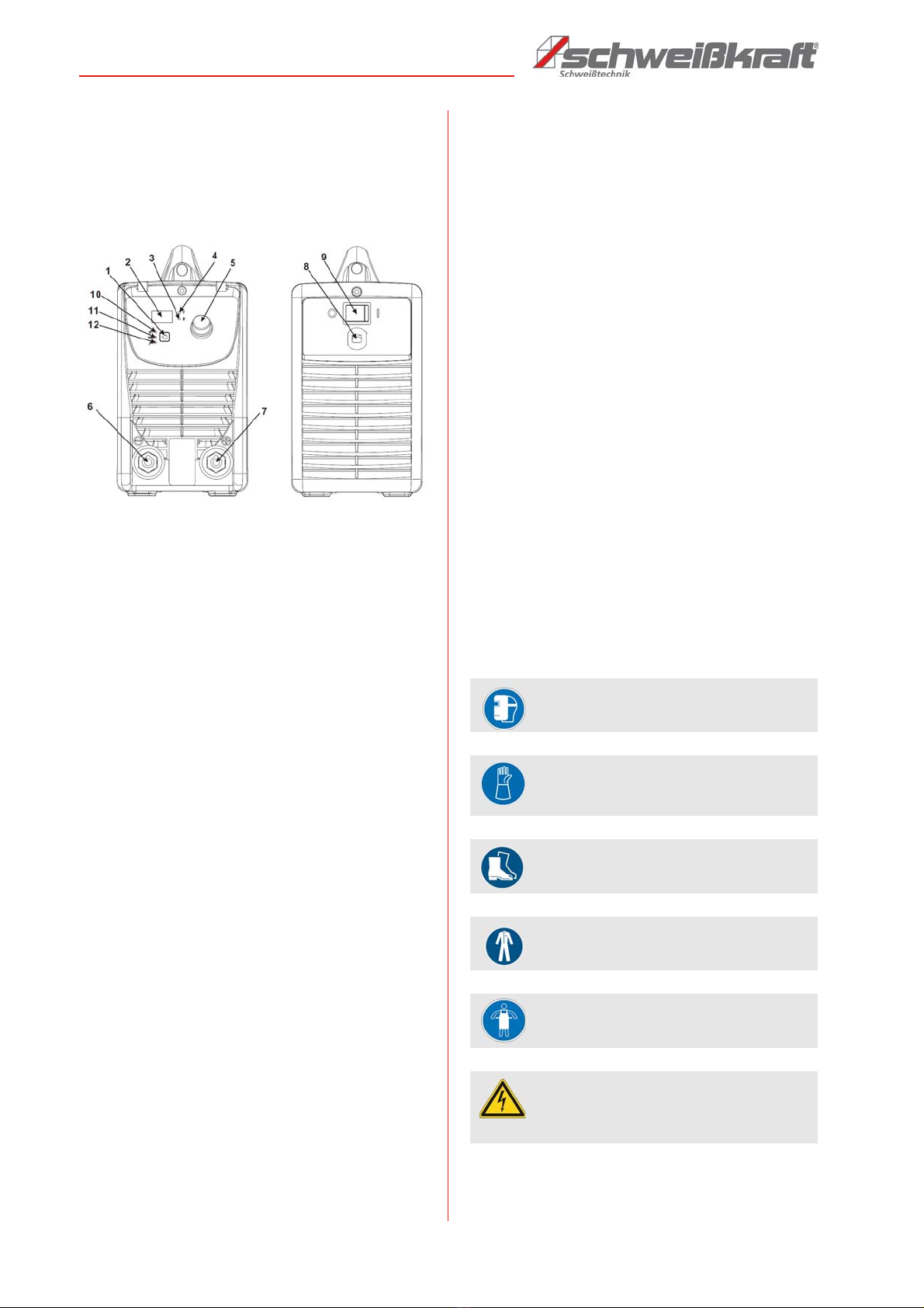
6 Operating principle
The EASY-STICK 121 welding unit is an electrode inver-
ter for welding with all common rutile, stainless steel and
cast iron electrodes with direct current as well as with
TIG function. The required welding current can be adju-
sted steplessly via a control dial. The Hot-Start function
provides stable ignition of the arc and the Anti-Stick
function prevents the electrode from sticking. These
functions are automatically activated and deactivated.
The Arc-Force control adjusts the dynamics to the wel-
ding process and can be controlled. The unit is cooled
with an air fan. If the permissible temperature of the po-
wer components is overshot, the welding current is auto-
matically switched off. This is indicated by a control lamp
on the control panel. The housing protects the compo-
nents against external influences and direct contact. De-
pending on the application, there are different degrees of
protection against penetration by solid bodies and water.
The degree of protection is indicated by the letters IP
followed by two digits: The first digit indicates the degree
of protection against solid bodies and the second digit
the degree of protection against water.
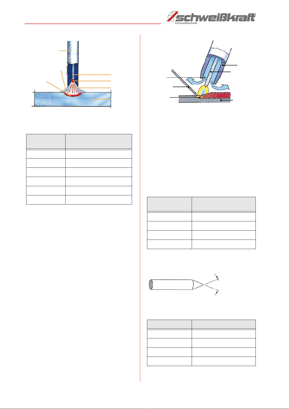
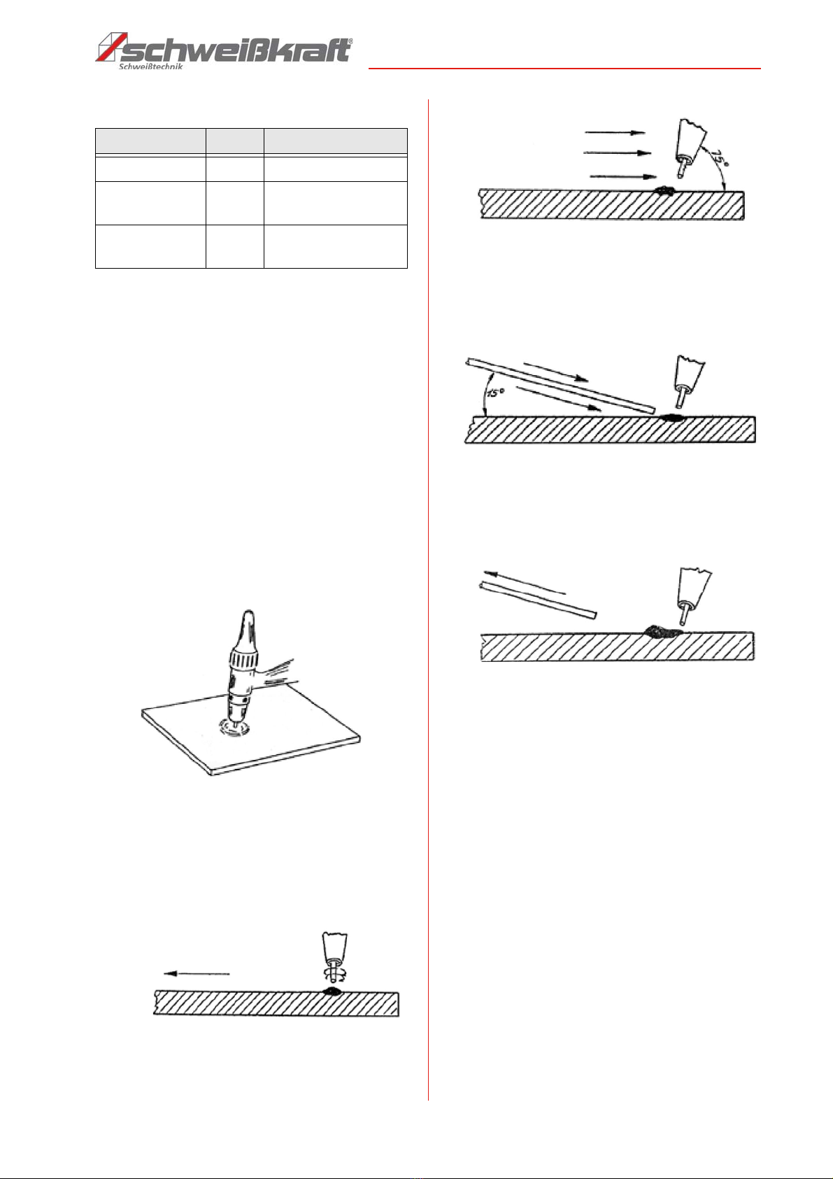
6.1 Principle of electrode welding
Electrode welding is an uncomplicated welding method
with which almost all metals can be welded. This method
can also be used outdoors and with special equipment
even under water. In electrode welding, the arc length is
determined by hand. The distance between the electro-
des determines the arc length. Welding is mainly carried
out under direct current; e.g. rutile electrodes are easy to
weld under minus-pole direct current; basic electrodes
under plus-pole direct current. The electrode is an arc
carrier and also an additional material. It consists of a
core wire and a coating. The coating protects the molten
pool from harmful atmospheric oxygen and stabilizes the
arc. In addition, a slag forms which protects and shapes
the weld seam. Depending on the thickness and compo-
sition of the coating, a difference is made between rutile
and basic electrodes. Rutile electrodes are easier to
weld and have a nice flat seam. The slag is also easier to
remove. It should be noted that many electrodes It
should be noted that many electrodes must be dried
back after prolonged storage, because moisture accu-
mulates from the air over time back after longer storage,
because moisture accumulates from the air over time.
Otherwise, electrode welding is a very common and
easy-to-use welding process.
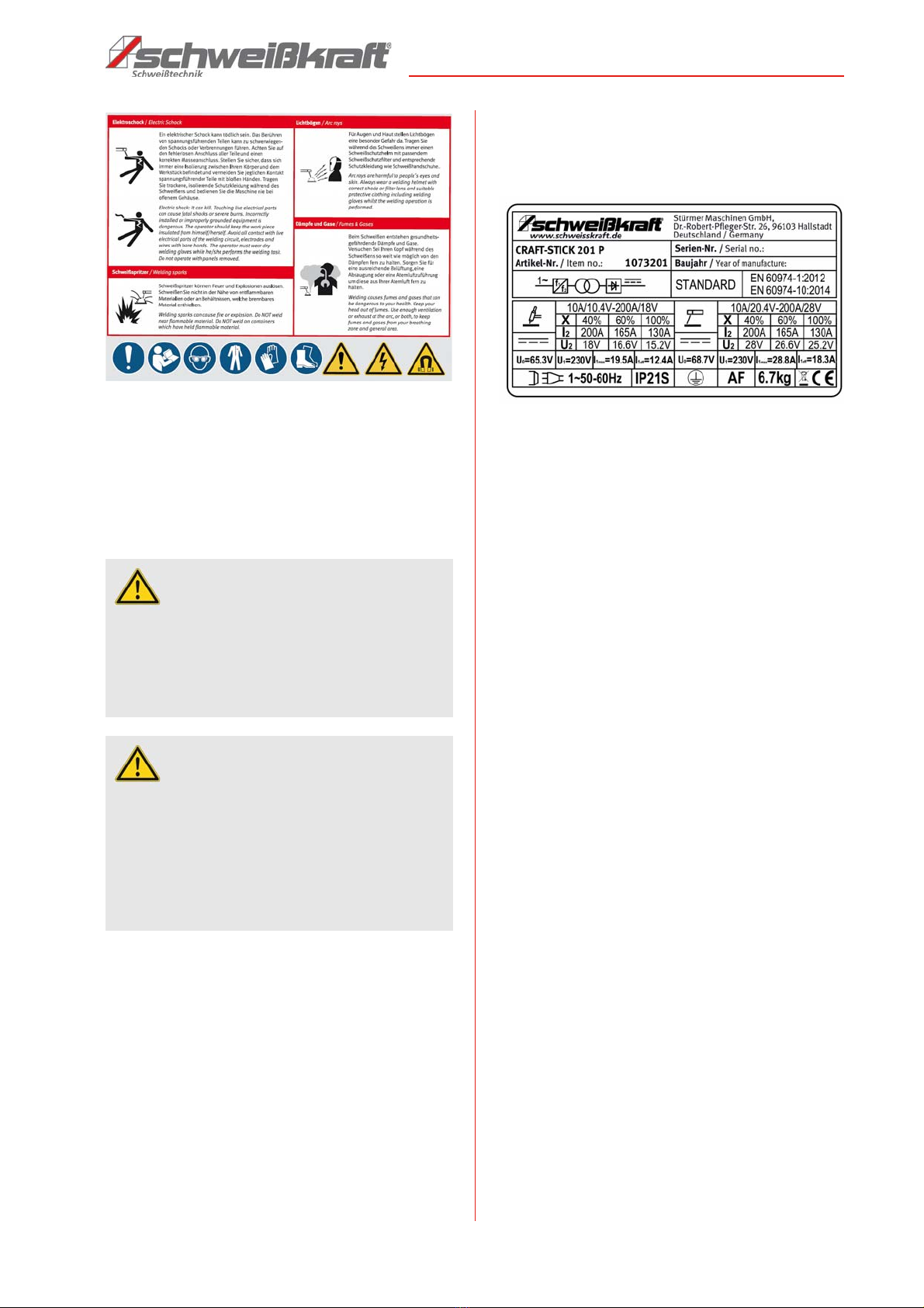
DANGER! ELECTRICAL VOLTAGE!
Do not use the device outdoors in the rain!
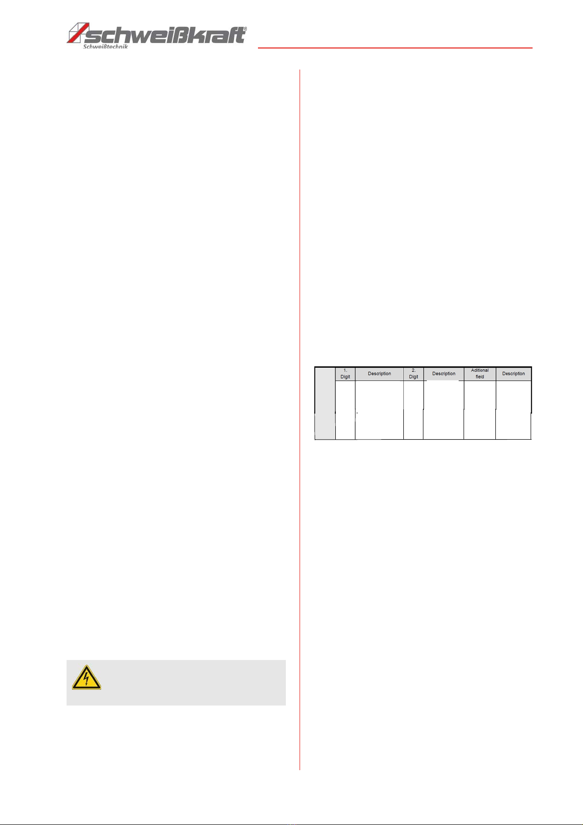
Protect
against solid
objects over
12 mm e.g.
hands, large
tools
21
Protected
against
vertically
falling
dripping
water
S
Tested
when
moving
parts are
at a
standstill
IP2
1