DRS Technologies Tamarisk 640 User manual

Tamarisk®640
17 μm 640x480 Long Wave Infrared Camera
Camera Control Software User Guide
Document No: 1012821
Revision: B

Tamarisk®Camera Control Software User Guide
i
©Copyright 2013, DRS TECHNOLOGIES, Inc.- All rights reserved.
13532 N. Central Expressway
Dallas, TX 75243
877.377.4783
www.drsinfrared.com
All rights reserved. The contents of this document may not be reproduced in whole or in parts
without the written consent of the copyright owner.
NOTICE
ALL STATEMENTS, INFORMATION, AND RECOMMENDATIONS IN THIS MANUAL ARE BELIEVED TO BE ACCURATE BUT ARE PRESENTED WITHOUT
WARRANTY OF ANY KIND. NOTWITHSTANDING ANY OTHER WARRANTY HEREIN, ALL DOCUMENT FILES AND SOFTWARE ARE PROVIDED “AS IS”
WITH ALL FAULTS. DRS DISCLAIMS ALL WARRANTIES, EXPRESSED OR IMPLIED, INCLUDING, WITHOUT LIMITATION, THOSE OF MERCHANTABILITY,
FITNESS FOR A PARTICULAR PURPOSE AND NONINFRINGEMENT OR ARISING FROM A COURSE OF DEALING, USAGE, OR TRADE PRACTICE.
IN NO EVENT SHALL DRS BE LIABLE FOR ANY INDIRECT, SPECIAL, CONSEQUENTIAL, OR INCIDENTAL DAMAGES, INCLUDING, WITHOUT
LIMITATION, LOST PROFITS OR LOSS OR DAMAGE TO DATA ARISING OUT OF THE USE OR INABILITY TO USE THIS MANUAL, EVEN IF DRS HAS
BEEN ADVISED OF THE POSSIBILITY OF SUCH DAMAGES.
Rev History
Revision Number Release Date Description
A 3/26/2012 Initial Release
Use with Firmware older than V01.00.0080
B 11/15/2013 Updated Document to include latest SW/FW including ICE
Strength Slider etc. Prepared for Public Release
Camera Link® is a registered trademark of the Automated Imaging Association.

Tamarisk®Camera Control Software User Guide
ii
TABLE OF CONTENTS
Table of Contents ...................................................................................................................ii
Acronyms and Abbreviations.................................................................................................iii
Reference Documents........................................................................................................... 1
Safety Instructions................................................................................................................. 2
1Introduction..................................................................................................................... 3
1.1 Supported Cameras .........................................................................................................3
1.2 System Requirements......................................................................................................3
1.3 Lens Calibration Requirements ........................................................................................4
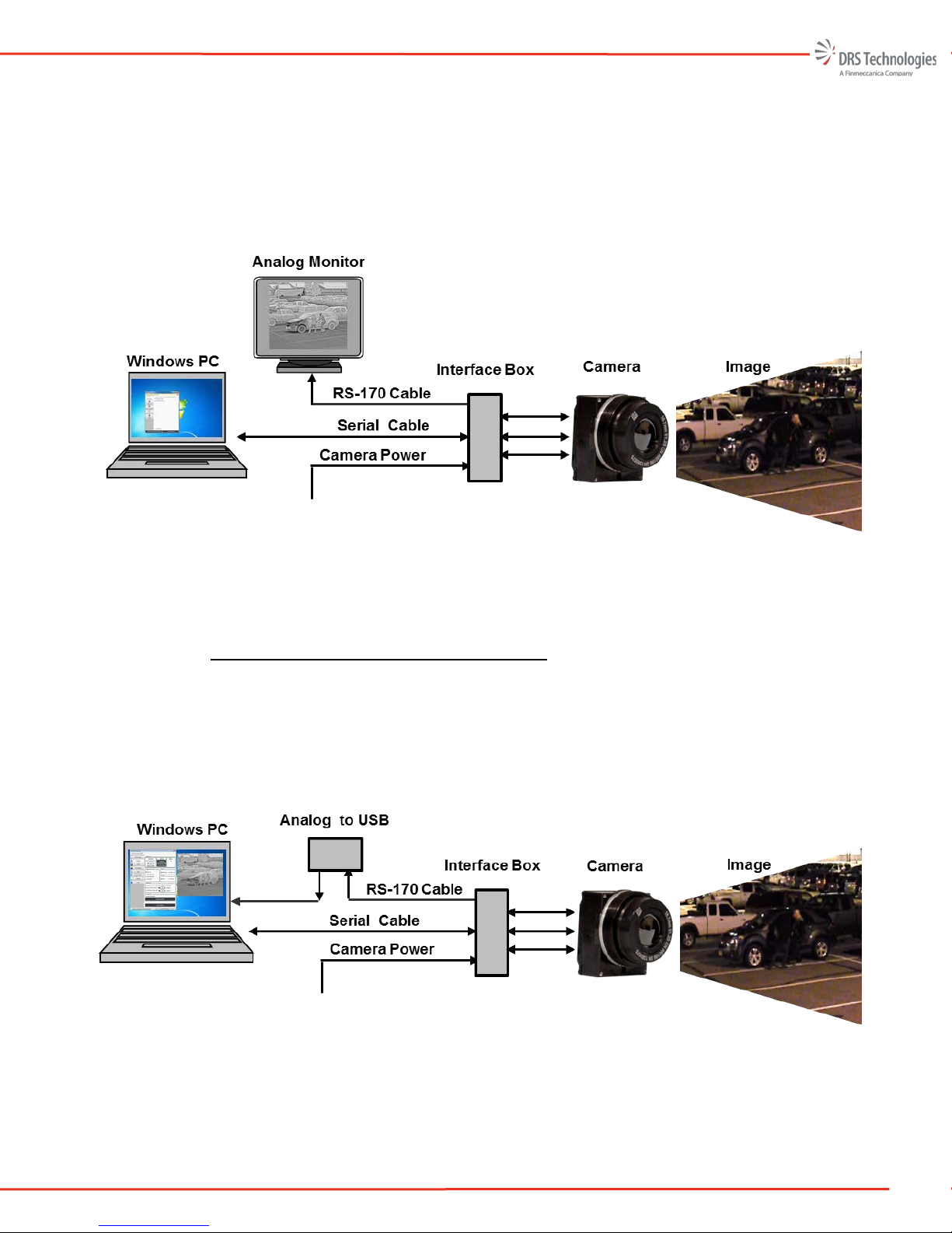
2Hardware Setup.............................................................................................................. 5
2.1 Hardware Configuration....................................................................................................5
3Software Installation ....................................................................................................... 8
3.1 Launching The Camera Control Software Installer ...........................................................8
3.2 Install Camera Control Software.......................................................................................9
4Set-up and Operation ................................................................................................... 14
4.1 Getting started................................................................................................................14
4.2 Starting the Camera Control Software............................................................................14
5Camera Control Software Operation............................................................................. 16
5.1 Information Tab..............................................................................................................17
5.2 Settings..........................................................................................................................17
5.3 Video..............................................................................................................................22
5.4 Colorization ....................................................................................................................25
5.5 AGC ...............................................................................................................................25
5.6 Pan and Zoom................................................................................................................30
5.7 Lens Calibration .............................................................................................................31
5.8 Pixel Map .......................................................................................................................40
5.9 Utilities............................................................................................................................42
6Uninstalling the Software.............................................................................................. 47
6.1 Removing The Software Using the Install Utility .............................................................47
6.2 Uninstalling The Software Using the Uninstall Prompt....................................................47
6.3 Uninstalling The Software via Control Panel..................................................................48
7Troubleshooting............................................................................................................ 49
7.1 No Attached Devices Found...........................................................................................49
7.2 No Video or Poor Video From the Camera.....................................................................55
7.3 Custom lens Calibration and Custom Pixel Map Tabs are non functional.......................56
7.4 Custom Lens Calibrated camera has poor video............................................................56

Tamarisk®Camera Control Software User Guide
iii
ACRONYMS AND ABBREVIATIONS
Abbreviation
Description
Abbreviation
Description
°C
Celsius
mm
millimeter
°F
Fahrenheit
ms
milliseconds
AGC
automatic gain control
MSB
Most Significant Bit
BPR
bad pixel replacement
MTU
Maximum Transfer Unit
CCA
circuit card assembly
MWIR
Mid-wave infrared
CL
center line
NETD
noise equivalent temperature difference
COMM
communication
NTSC
National Television System Committee
CSC
Computer Software Component
NUC
non-uniformity correction
CSCI
Computer Software Configuration Item
NVTHERM
Night Vision Thermal Analysis Tool
CSU
Computer Software Unit
OEM
original equipment manufacturer
dB
decibels
OLA
Optical Lens Adapter
DSP
digital signal processor
P
probability
ESD
electrostatic discharge
POL
polarity
E-Zoom
electronic zoom
psi
pound per square inch
FOV
field of view
Rev
revision
FPA
Focal Plane Array
ROI
region of interest
ft
feet
SC
split configuration
G
gravitational force
SWIR
Short-wave infrared
g
gram
TBD
To Be Determined
GUI
graphical user interface
TCR
Temperature coefficient of resistance
H
height
TIM
Thermal Imaging Module
HFOV
horizontal field of view
UART
Universal Asynchronous Receiver Transmitter
I/O
input/output
UAV
unmanned aerial vehicle
ICD
Interface Control Document
UFPA
Un-cooled Focal Plane Array
ICE
Image Contrast Enhancement
USB
Universal Serial Bus
ID
identification
V
Vertical or Voltage
IR
infrared
VDC
volts direct current
IRS
Interface Requirements Specification
VGA
video graphics array
km
kilometer
VOx
Vanadium Oxide
LR
lower right
W
width or Watt
LWIR
long-wave infrared
μm
micron (micrometer)

Tamarisk®Camera Control Software User Guide
1
REFERENCE DOCUMENTS
The following documents form part of this specification. In the event of a conflict between
documents referenced herein and the contents of this specification, the contents of this specification
shall be considered a superseding requirement.
Document No: 1002593 Tamarisk®640 User Manual
Document No: 1012820 Tamarisk®640 Electrical Interface Control Document
Document No: 1012819 Tamarisk®640 Software Interface Control Document
Document No: 1003727 Tamarisk®640 Mechanical Interface Control Document

Tamarisk®Camera Control Software User Guide
2
SAFETY INSTRUCTIONS
NOTIFICATIONS: CAUTION, WARNING AND NOTE
The following is a list of notifications and their accompanying symbol that may be found through this
document to alert the reader to potential risks and to minimize the potential for personal injury and or
damage to the product. When a notification is present, it is important that the user review and
understand all statements related to the notification before proceeding. If questions arise, please
contact your authorized dealer or DRS Technologies.
Notifications are preceded by a symbol and followed by highlighted text. Three types of notifications
are typically used and are defined below:
CAUTION
A caution is a procedure, practice, or condition that, if not strictly followed, may
result in personal injury or damage to the equipment that may impede product
performance.
WARNING
A warning is intended to alert the user to the presence of potentially harmful
circumstances and provide precautionary guidance for mitigating risk of personal
injury and or damage to the product.
NOTE
A note is a statement that clarifies or is used to emphasize important information.
1. Read all instructions
2. Keep these instructions for future reference.
3. Follow all instructions
4. Heed all warnings.
5. Do not submerge this apparatus in liquid of any kind.
6. Clean per recommended instructions using dry non-abrasive cloth.
7. Do not install near any sources of intense heat such as radiators, furnaces,
stoves or other apparatus that regularly produce excessive heat.
8. Refer all servicing to qualified service personnel.

Tamarisk®Camera Control Software User Guide
3
1INTRODUCTION
The Camera Control Software provides an easy to use, graphical interface which allows the user to
fully evaluate the camera’s functions and features. This user guide describes the installation
requirements, installation procedure, and provides details on how to use the Camera Control Software
to configure the camera, display status information, and perform image processing.
NOTE
This guide is based on version 1.6 or later of the DRS Camera Control Software.
1.1 SUPPORTED CAMERAS
This User Guide explains the operation of with the Camera Control Software version 1.6 or later.
This version supports the following cameras:
1. Tamarisk®640
2. Tamarisk®320
3. Zafiro™640
4. UC640
1.2 SYSTEM REQUIREMENTS
To install and run the Camera Control Software, ensure the host PC supports the following:
1. Operating System: Microsoft Windows7 (64-bit/32-bit), or Windows XP (64-bit/32-bit)
with SP3
2. CPU: 1GHz or faster
3. Memory: 512MB of RAM (1GB recommended) and 500 MB of available hard-disk
space
4. CD/DVD-ROM drive
5. USB 2.0 port or a serial port
6. Display: 1024×768 resolution or above
7. Adobe PDF reader – for viewing the help files
8. The following are optional
9. Analog frame grabber which supports Microsoft’s DirectShow API
10. Camera Link frame grabber which supports Microsoft’s DirectShow API

Tamarisk®Camera Control Software User Guide
4
1.3LENS CALIBRATION REQUIREMENTS
The following hardware is needed to calibrate the camera successfully:
1. Pass Key to enable the Lens Calibration tab
2. A Tamarisk®with lens focused at infinity running:
a. FPGA RTL ver: V01.00.0080 or newer
b. CPU SW ver: X1.P1.01.13.13 or newer -OR- X1.Px.00.xx.xx
3. A USB cable or RS232 cable and power
4. One or two thermally stable black bodies. Ideally, the calibration process uses a
controllable black body, but any thermally stable and uniform body is acceptable. The
black body must completely fill the field of view with a uniform scene. DRS recommends
the following black body manufactures and models:
a. Santa Barbara Infrared, Inc.
www.sbir.com
Model: Infinity black body and controller
b. CI Systems
www.ci-systems.com
Model: sR-800

Tamarisk®Camera Control Software User Guide
5
2HARDWARE SETUP
2.1 HARDWARE CONFIGURATION
In this section, three different configurations for viewing your camera’s output video will be
presented, including solutions for both analog and digital video. Although the physical interface may
vary from camera to camera, the schema outlined below will remain valid for the products listed in
section 1.1 above.
Table 1, presents three different approaches for viewing your camera’s output video as well as the
recommended hardware to support that given approach. An illustration is provided to document each
connection and demonstrate what the given set-up may look like.
Table 1. Hardware Configuration Set-up Overview
Display Configuration Required Hardware Illustration
Analog video to an external
monitor
Laptop
Analog Display
USB to USB mini cable
Camera Module
Camera Interface Cable
Camera break out box
Coax cable
Analog video displayed on
the PC
Laptop
USB to analog frame grabber
USB to USB mini cable
Camera Module
Camera Interface Cable
Camera break out box
Coax cable
Camera Link (digital) video
displayed on the PC
Laptop
Camera Link frame grabber
Camera Link cable
USB to USB mini cable
Camera Module
Camera Interface Cable
Camera break out box
2.1.1 Connecting to an Analog Monitor
The simplest way to evaluate the camera is to configure the hardware as shown in Figure 1. The
user simply needs to apply power and connect the RS-170 cable to an analog monitor. For some

Tamarisk®Camera Control Software User Guide
6
cameras, a USB cable may be used to provide both power and control. The user will immediately
see video displayed on the analog monitor. To manipulate or change the camera settings a serial
communication link (serial RS232 or USB ) is required. The camera may be control through
issuing serial commands via the serial link or by using the Camera Control Software described
herein.
Figure 1. Analog Video Displayed on an Analog Monitor
2.1.2 Connecting to an Analog Frame Grabber
Alternatively, an analog video-to-USB frame grabber (as shown in Figure 2) may be used to
display the camera’s output video. In this case, the RS-170 feed from the camera or interface box
is connected to an analog video-to-USB frame grabber. To display the video on screen please
follow the instructions that came with your analog-to-USB frame grabber.
The frame grabber allows the user to capture video or images and analyze or view them later.
Figure 2. Analog Video Displayed on a PC, via Analog Frame Grabber

Tamarisk®Camera Control Software User Guide
7
2.1.3 Connecting to a Camera Link Frame Grabber
This method provides the highest quality image for display. Figure 3, illustrates the set-up for
viewing digital video (14-bit or 8-bit) using CameraLink®. Simply connect the CameraLink®
cable to the PC’s CameraLink®frame grabber card on one end and to the CameraLink® connector
on the interface box. Besides capturing digital video and images, Camera Link adapters provide a
host of control features such as data capture rates and video compression formats. Please follow
the instructions that came with your CameraLink® capture card to display the image on screen. A
list of compatible frame grabbers is available and can be found in your Tamarisk®Product
Documentation Package.
Figure 3. Digital Video Displayed on a Digital Display via Digital Frame Grabber

Tamarisk®Camera Control Software User Guide
8
3SOFTWARE INSTALLATION
DRS provides Tamarisk®Camera Control Software in various media formats. Please refer to the
Tamarisk®User Manual and or www.drsinfrared.com for a list of accessory items including part
numbers. The Tamarisk®Camera Control Software may be download directly from our web site.
3.1 LAUNCHING THE CAMERA CONTROL SOFTWARE INSTALLER
Follow the instructions below to install the Camera Control Software GUI on your PC or laptop.
Download software from www.drsinfrared.com or insert flash media into your PC. Refer to Figure
4.
Figure 4. Internet Download or Flash Media Install
Using Windows Explorer, select the drive corresponding to the media was just inserted. Look for the
file name: DRS Camera Control Software Setup. Refer to Figure 5.
Figure 5. Software Install

Tamarisk®Camera Control Software User Guide
9
Initiate the installation process by selecting (double mouse click) DRS Camera Control Software
Setup icon; Refer to Figure 6.
Figure 6. Software Install
3.2INSTALL CAMERA CONTROL SOFTWARE
Once the user double clicks the DRS Camera Control Software Setup icon, the image shown in Figure
7 appears. If the Install Wizard detects that an older version of the Camera Control Software is
installed, the user will be asked if he wants to install a new version. It is highly recommended to exit
setup and uninstall the previous version prior to installing the new version. At any point prior to
clicking the “Install” button; the user can cancel the installation by clicking the “Cancel” button.
Figure 7. Welcome to the InstallShield Wizard
Software License Agreement: The Software License Agreement screen is shown in Figure 8. Once
the agreement is read the terms accepted, the user selects “I accept the terms in the license
agreement”. The user can print the agreement by selecting the “Print” button.

Tamarisk®Camera Control Software User Guide
10
Figure 8. Software License Agreement
LGPL License: The LGPL License Agreement is shown in Figure 9. Once you have read the
agreement and accept the terms, select “I accept the terms in the license agreement”. The user can
print the agreement by selecting the “Print” button.
Figure 9. LGPL License Agreement
Destination Folder: The default installation directory is shown in Figure 10. The user can change the
installation directory by clicking on the “Change” button. Select next to confirm installation
destination.

Tamarisk®Camera Control Software User Guide
11
Figure 10. Destination Folder
Setup Type: Figure 11 shows the Setup Type screen. The user can select between a “Complete”
(recommended) or “Custom” install, then select Next.
Figure 11. Setup Type

Tamarisk®Camera Control Software User Guide
12
Ready to Install the Program: The InstallShield Wizard has enough user information to complete the
installation. At this point the user can cancel the installation. Once the “Install” button is pressed, the
Wizard will make sure the system meets the minimum installation requirements and complete the
installation. The Ready to Install the Program screen is shown in Figure 12.
Figure 12. Ready to Install the Program
Installing DRS Camera Control Software: The InstallShield Wizard status shows the changes that are
made during the installation; a progress bar also is provided. A command prompt window may
briefly appear; this is a normal part of the installation. Figure 13 shows the Installing DRS Camera
Control Software screen.
Figure 13. Installing DRS Camera Control Software
Within approximately three minutes the InstallShield Wizard Completed screen appears. The
installation is now complete. Select Finish. By default the DRS Camera Control Software will not

Tamarisk®Camera Control Software User Guide
13
immediately start when the “Finish” button is pressed. The user can select the “Launch DRS Camera
Control Software” checkbox and upon selecting “Finish” and the DRS Camera Control Software will
start. Figure 14 shows the InstallShield Wizard Complete screen.
Figure 14. InstallShield Wizard Completed
Once the installation is complete the user will notice that an icon was added to the desktop and a DRS
Technologies folder is added to the programs list.

Tamarisk®Camera Control Software User Guide
14
4SET-UP AND OPERATION
4.1 GETTING STARTED
Make sure your camera is connected and powered up. Refer to the user manual for your specific
camera to ensure the proper power-up procedure is followed.
Connect the USB or RS232 serial cable to the proper port on your PC or laptop. If connecting to the
camera via USB for the first time, drivers will need to be installed. You can skip obtaining the
drivers from windows update since these drivers were installed on the PC as part of “Launching the
Camera Control Software Installer” on page 8.
4.2 STARTING THE CAMERA CONTROL SOFTWARE
Once your device is properly connected and powered, start the Camera Control Software by clicking
on the icon (refer to Figure 15).
Figure 15. DRS Control Software Icon
The software will automatically search for and connect to any supported and attached camera(s) (refer
to Figure 16).
Figure 16. DRS Control Software Icon
While the system is searching you may press the ESC key to manually add a camera.
If the key ESC is pressed or no device is found, the No Attached Devices Found dialog box is
displayed (refer to Figure 17). Check to verify that the device drivers have been installed. Go to
Control Panel, select programs and features and look for FTDI Driver Install Package. If drivers are
present then follow the steps below to manually connect the camera. If drivers are not found, then
install drivers from the media used when installing the software.
Click Manually Add Device to open the Add Devices dialog box (refer to Figure 18).

Tamarisk®Camera Control Software User Guide
15
Figure 17. DRS No Attached Devices Found
Select the camera from the pull-down menu or select “Auto Detect Device.” Additionally, the user
may select the COM port and Baud rate. The default baud rate for connecting through USB is
921600. The default baud rate for connecting through a RS232 serial interface is 57600. Figure 18
illustrates the configuration needed to connect to the camera via the RS232 interface; The COM port
used is PC dependent. Click “Add Device” to connect to the selected camera.
Figure 18. DRS Control Software Icon

Tamarisk®Camera Control Software User Guide
16
5CAMERA CONTROL SOFTWARE OPERATION
In this section the operation of the Camera Control Software GUI is explained by stepping through
the various tabs and providing an explanation of features and functions.
The Camera Control Software is capable of supporting multiple cameras within the same application.
A new camera tab, identified by the camera’s serial number (see Figure 19) is displayed for each
additional camera. This feature is available only when using a USB cable (and not a USB-to-serial
RS232 cable) to communicate with your camera. For example, to configure and control three
Tamarisk®cameras, connect each camera (via USB) from the camera’s break out box to the PC as
shown in Table 1. Hardware Configuration Set-up Overview. Open the Camera Control Software.
The software will display three separate camera tabs; each tab is uniquely identified by the camera’s
serial number.
Additionally, multiple instances of the Camera Control Software may be opened at a time by
launching multiple Camera Control Software applications and manually connecting your cameras as
desired.
There are several tabs available to assist you in communicating with and controlling your connected
Tamarisk®cameras. They are:
1. Information
2. Settings
3. Video
4. Colorization
5. AGC
6. Pan and Zoom
7. Lens Calibration
8. Pixel Map
9. Utilities
10. Help
Additionally, there are two functions that may be present on the Camera Control Software window,
namely, Search for New Connected Devices and Show Live Video. See section 5.9 for details.
Other manuals for Tamarisk 640
2
Table of contents
Other DRS Technologies Security Camera manuals