DryMax MHT100A-1 User manual

DryMax Canada
320 Brunel Road
Mississauga, On, L4Z 2C2
Phone: 1.905.897.8485
Toll Free: 1.888.486.4445
e-mail: [email protected]
wwwww.drymaxairdryers.ca
Visit our website @ www.drymaxairdryers.ca - For brocheurs, manuals, drawings & technical data

DRYMAX
DRYMAX
DRYMAX
DRYMAX
905.897.8485

3
RECEIVING AND INSPECTION
1. The dryer cannot be tilted on its side or upside down during shipping.
2. Use forklift from the bottom of the dryer when installing or moving.
3. Dryers are shipped F.O.B. factory. Immediately upon arrival check the dryer for possible
damage. If damage is found, report it to the carrier and file a damage claim.
4. Check dryer data label to be sure you have the right dryer. Check the data labels voltage and
amperage to be sure it is correct and the one you ordered.
5. Check the refrigeration gauges for pressure. If gauges read 0 PSIG STOP. Do not start dryer. Call
your distributor for service. This could mean there is a leak and the refrigerant has leaked out.
HOW THE AIR DRYER WORKS
MHT Series refrigerated compressed air dryers use refrigeration cooling to condense entrained
moisture out of the compressed air stream. Warm saturated air enters the air-to-air heat exchanger
at the dryer inlet. (1)
In the air –to- air heat exchanger the inlet air is pre-cooled by the outgoing cold air. The
pre-cooled air then enters the air to refrigerant heat exchanger (3) were it is cooled to its lowest
point by the refrigeration in the evaporator. As the air is cooled moisture in the air changes from
a vapor to a liquid. The liquid condensate is removed from the airstream by the separator (4)
and discharged from the dryer by the automatic drain valve. (5) The cold air is reheated by
incoming warm air as it passes back through the air-to-air heat exchanger. Pre-cooling the inlet
air reduces the heat load on the refrigerant compressor, permitting the use of a smaller refrigerant
compressor. (2) The out going cold air is reheated by the in coming hot air. As a result the outlet
air is warmed up as it leaves the dryer. This prevents the outlet pipe from sweating. The air exits
the dryer and is now clean and dry, ready for use.

4
INSTALLATION AND LOCATION
1. Ventilation – Install dryer only in a well-ventilated clean, dry area only and keep at least 3 feet
between the dryer, other equipment and the walls.
2. Dryer Location – Make sure there is approximately 3 feet around the dryer for service and
maintenance purposes. Do not install the dryer outside. The air dryer must not be exposed
to direct sunlight, rain or snow. Do not install the dryer in an environment with fire, high
temperatures or low temperatures.
Make sure the dryer is installed in an environment that is clean and dry. Dust and dirt particles
will clog the air-cooled condenser. A clogged and dirty condenser will reduce the performance
of the dryer and will eventually cause damage to the dryer.
3. Ambient Temperatures – Suitable ambient temperature for the refrigerant dryer is a minimum
of 35 F to a maximum of 110 F. The performance of the dryer will be significantly decreased
when the air dryer is subject to temperatures higher than 110 F. For installations with ambient
temperatures higher than 110 F it is recommended to use a water-cooled condenser on the
dryer. Contact your dealer for details.
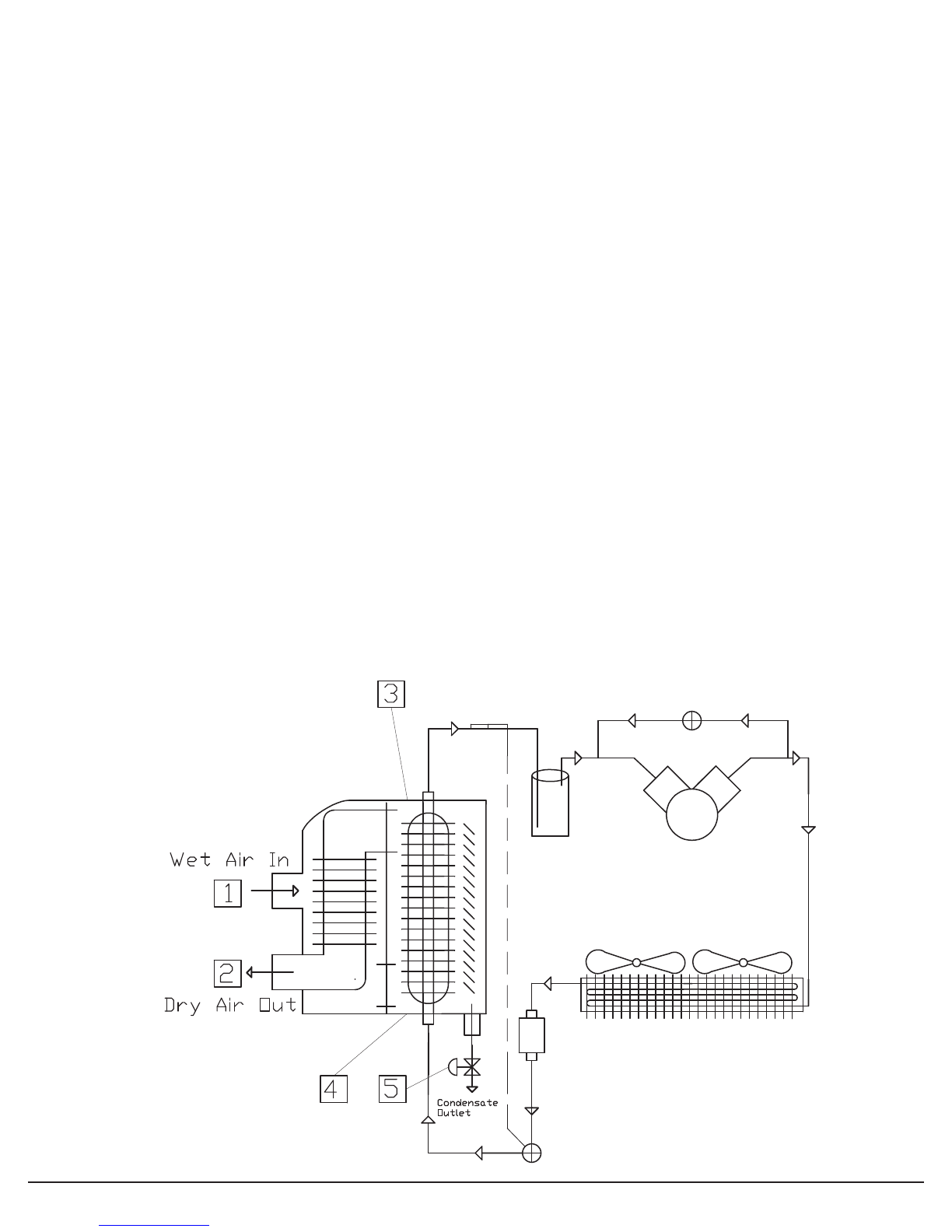
4. Selecting Proper In and Out Piping and Piping Design – Pipe diameter should be
sized according to air flow requirements. Do not mix the air inlet and outlet air flow. It
is recommended that a vibration absorber be installed on the dryer inlet and outlet to
eliminate vibration from the compressor. Do not use the inlet and outlet of the air dryer to
support the weight of the air piping.
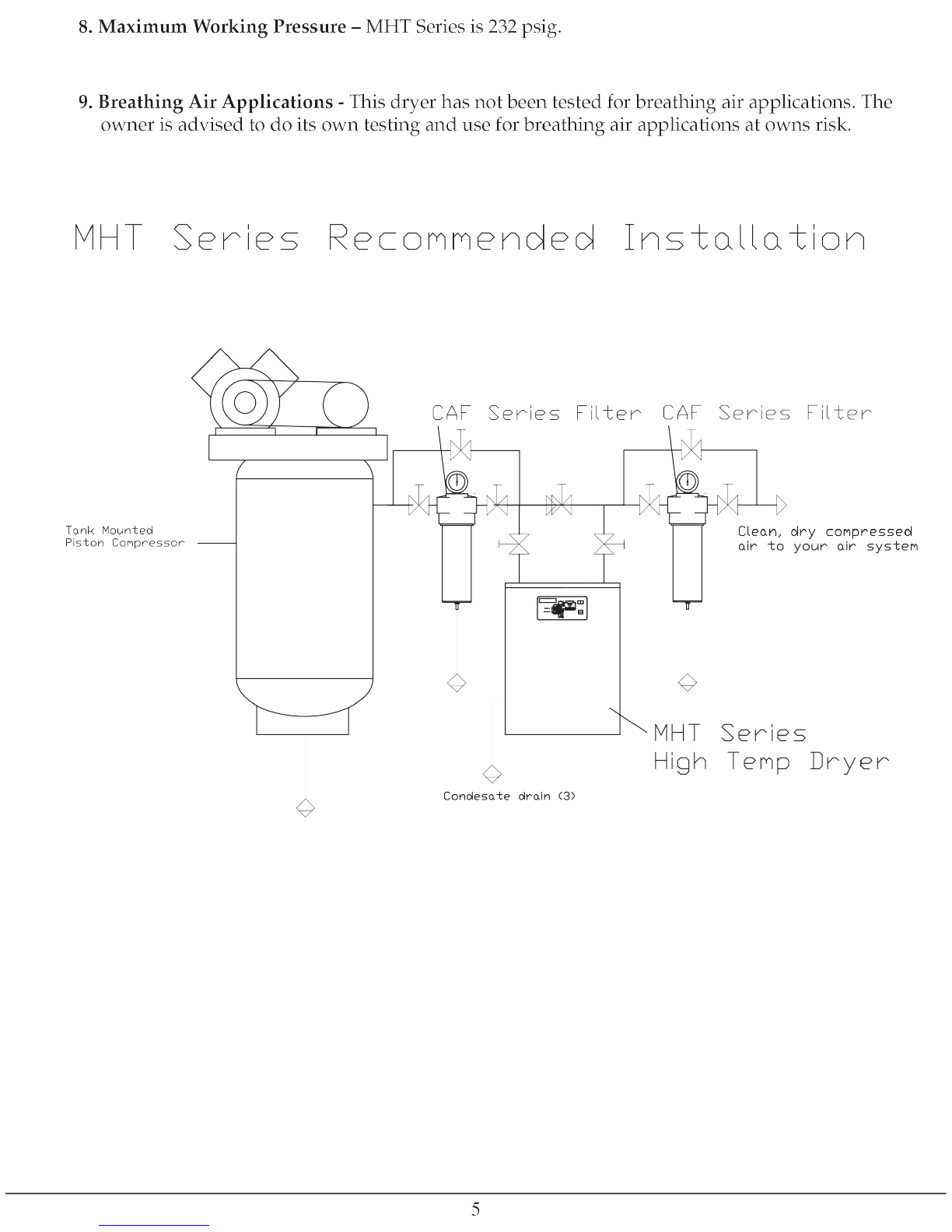
5. 3 valve bypass and Isolation valves - should be installed on the air dryer outlet and inlet ports
to allow for bypassing, depressurizing, and proper maintenance and servicing of the air dryer.
6. Condensate Drains – Condensate drains must be properly piped from the dryer to prevent
moisture re-entrainment. The dryer is equipped with an automatic drain valve that controls the
discharge of the condensate and a manual valve to manually drain condensate. The user must
run a drain line to an environmentally approved condensate collection/disposal system.
7. Electrical Installation – The dryer data label lists the electrical power requirements for the air
dryer. The user must confirm that the line voltage matches the voltage listed on the data label.
(Warning – Operating the air dryer with improper line voltage will void the warranty.) Provide
the proper size wire, disconnect switches and fuses in accordance with applicable codes. Field
wiring must comply with local and national fire safety and electrical codes. Standard dryer’s
enclosures and controls are designed to meet NEMA 1 Type 1 electrical standards. All wiring
is complete. Connect power leads as indicated in the electrical schematic. Ground the frame
properly. Once power is connected turn the power on to the dryer. Leave the power on for 6
hours before you turn the dryer on. This will energize the crank case heater and boil off any
liquid refrigerant in the crank case. Failure to do this may damage the refrigerant compressor
and will void the warranty.


6
DATA LABEL
The data label is affixed to the outside of the cabinet. This label identifies the air dryer’s model and
serial number and important technical data. Before installing the dryer check all the information on
the data label for the correct model and voltage. If the model number and voltage are incorrect do no
install the dryer. Do not put power to the dryer. Call your local distributor.
DATA LABEL
The data label is affixed to the outside of the cabinet. This label identifies the
air dryers model and serial number and important technical data. Before
installing the dryer check all the information on the data label for the correct
model and voltage. If the model number and voltage are incorrect do no
install the dryer. Do not put power to the dryer. Call your local distributor.
DATA LABEL
Model MHT100A-1
Serial #
Date of MFG.
Voltage
115v-1ph-
60hz
Voltage Range 103.5-126.5
RLA 13
LRA 69
Min Circuit Ampacity 18
Max Fuse Size 30
Maximum Inlet Air Temp - F 110
Min/Max. Ambient Temp - F 110/45
Ref. System Design - PSI 350/150
Suction/Discharge - PSI 70/225
Maximum Pressure (PSIG) 232
Ref. Compressor HP 1 1/2
Refrigerant Type R134a
Refrigerant Charge 1.5 lbs
MACAIR INC. REFRIGERATED AIR DRYER
DRYER CONTROLS
6


8
START UP
The following procedure must be followed to start your air dryer. Failure to follow this start up
procedure will void your warranty. If problems occur during start up, contact your distributor.
1. Turn off the On/Off switch.
2. Verify the main electrical supply voltage matches the voltage specified on the data label.
3. Check the proper connection and support of the compressed air lines to the dryer: check dryer
bypass and isolation valve system.
4. Confirm that the inlet and ambient air temperature, pressure and flow to the dryer meet the
specified requirements.
5. Confirm that the condensate drain lines from the separator are properly piped to an environ-
mentally approved disposal system
INITIAL RUN PROCEDURE
After start up and checks are complete and after the main electrical power to the dryer has been
turned on for at least 6 hours (only for 460-3-60 & 230-3-60 dryers), follow the procedure below to
put the dryer in operation:
1. Turn ON the dryer ON/OFF switch.
2. Let the dryer run for 15 minutes. (For 460-3-60 & 230-3-60 dryers After 15 seconds observe the
refrigerant suction pressure gage. It should start to pull down immediately. (This will indicate
that L1,L2,L3 is connected for proper rotation. If the pressure does not pull down switch 2 of
the L1,L2,L3 leads.)
3. Check the refrigerant suction pressure gage:
Should read: On R134a dryers. (28 psig to 34 psig)
Only: MHT75, MHT100,MHT130
4. Check the DEWPOINT TEMP INDICATOR. After about 15 minutes This should read
35 F to 39 F.
5. Verify that the condenser fan motor is operating. The fan will cycle on and off.
6. Confirm that condensate is discharging from the condensate drain. This may take 30 -60
minutes.

9
HOW TO SET THE CONDENSATE DRAIN OPEN & CLOSED TIME
(LOCATE DRAIN VALVE)
1. The OPEN (ON) time is adjustable from 0.5 sec to 10 sec. Drains are set at factory to open for 6
sec. When drain opens the on light will light
2. The CLOSED (OFF) time is adjustable 0.5 min to 45 min. Drains are set at factory to stay closed
for 10 min. When drain is closed the off light will light.
You may increase or decrease this based on moisture levels in the air.
Push the TEST button to manually open the drain valve.
HOW TO MAKE MINOR REFRIGERANT SUCTION PRESSURE ADJUSTMENTS.
1. Keep dryer running under a no load by turning off or bypassing the compressed air.
2. Remove dryer top and locate the Hot Gas Bypass Valve.
3. Remove cap on Hot Gas Bypass Valve and using an allen wrench turn valve counter clockwise
to decrease the suction pressure and clockwise to increase the suction pressure. Make ½turn
adjustments and wait 2 to 3 minutes for suction pressure to stabilize. Make more adjustments if
needed.
(Minor Pressure Adjustments not covered under warranty.)
MHT 60 & MHT 130 MHT 25 & MHT 40

10
NORMAL MAINTENANCE PROCEDURES AND CHECKS
1. Daily Maintenance
• Check the operation of the automatic drain valves at least once during each eight
hour shift.
• Check Dewpoint Indicator to make sure it is the proper range
• Check suction pressures gauge to make sure it is the proper range.
• Make sure condenser coil is clean and unobstructed.
• Make sure the high temp warning light is not on.
2. Weekly Maintenance
• Clean Air cooled condenser coils - Blow off all dust and dirt that is on the condenser
fins with a compressed air maintenance gun.
• While cleaning the condenser fins do not damage fins.
WARNING - DRYER FAILURE DUE TO A DIRTY CONDENSER IS
NOT COVERED UNDER WARRANTY
3. Condensate Drain Maintenance
• Push the Push to Test Button to verify drain operation.
• Check the open time.
• Check the closed time.
If drain is not opening the drain should be dis-assembled, cleaned and checked for defects.
DANGER – This should only be done by a qualified service technician.
• Close the isolation valve before the drain.
• Remove the power unit and timer.
• Remove solenoid coil.
• Dis-assemble valve and check for debris and or defective spring or valve parts.
• Clean out any debris and re-assemble the valve.
•
If there are defective or broken valve parts contact your distributor for a new drain valve.
DANGER
Dismantling or working on any component in the air dryer or the compressed air system under
pressure may cause serious personal injury and equipment failure. Before dismantling any part of
the air dryer or compressed air system completely vent the internal pressure to the atmosphere.
Only qualified service persons should attempt to work on the air dryer.
Solenoid Coil
Power Unit
& Timer

11
DATE CLEAN SERVICE AMBIENT SUCTION DISCHARGE AIR
CONDENSER DRAIN TEMP PRESSURE PRESSURE PRESSURE
MAINTENANCE LOG

ProvinceofOntario
DRYMAX
DRYMAX
DRYMAX
DRYMAX
DRYMAXINC
SERVICEDEPARTMENT
905.897.8485
Table of contents