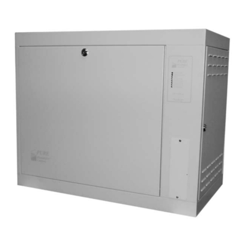
Duke FLEXTECH FTU-5 User manual

OWNER'S MANUAL
IMPORTANT INFORMATION, READ BEFORE USE.
PLEASE SAVE THESE INSTRUCTIONS.
This manual is Copyright © 2014 Duke Manufacturing Company. All rights reserved.
Reproduction without written permission is prohibited. Duke is a registered
trademark of the Duke Manufacturing Company.
Duke Manufacturing Company
2305 N. Broadway
St. Louis, MO 63102
Phone: 314-231-1130
Toll Free: 1-800-735-3853
Fax: 314-231-5074
www.dukemfg.com
P/N 169696B
07/16/2014
FLEXTECH™
HUMIDIFIED
HOLDING CABINET
STACKED
CONFIGURATION
Model:
FTU-5

Owner's Manual for DUKE FlexTech
Humidied Holding Cabinet
2

3
Owner's Manual for DUKE FlexTech
Humidied Holding Cabinet
TABLE OF CONTENTS
IMPORTANT SAFETY INSTRUCTIONS ............................................................................4
SPECIFICATIONS...............................................................................................................8
MAIN FEATURES................................................................................................................10
INSTALLATION ...................................................................................................................11
OPERATING INSTRUCTIONS............................................................................................19
CARE AND CLEANING.......................................................................................................22
DOOR ADJUSTMENTS AND GASKET MAINTENANCE ...................................................25
PROGRAMMING CONTROLS............................................................................................27
ERROR FAULT MESSAGING.............................................................................................30
TROUBLESHOOTING .......................................................................................................36
WIRING DIAGRAM .............................................................................................................38

Owner's Manual for DUKE FlexTech
Humidied Holding Cabinet
4
IMPORTANT SAFETY INSTRUCTIONS
Throughout this manual, you will nd the following safety words and symbols that signify important
safety issues with regards to operating or maintaining the equipment.
WARNING
INDICATES A HAZARDOUS SITUATION WHICH, IF NOT
AVOIDED, COULD RESULT IN DEATH OR SERIOUS INJURY.
CAUTION
INDICATES A HAZARDOUS SITUATION WHICH, IF NOT
AVOIDED, COULD RESULT IN MINOR OR MODERATE
INJURY.
CAUTION
INDICATES IMPORTANT INFORMATION
INDICATES ELECTRICAL SHOCK HAZARD WHICH, IF NOT
AVOIDED, COULD RESULT IN DEATH OR SERIOUS INJURY
AND/OR EQUIPMENT DAMAGE.
INDICATES HOT SURFACE WHICH, IF NOT AVOIDED, COULD
RESULT IN MINOR OR MODERATE INJURY. SPECIFICALLY,
RISK OF BURN FROM HEATING ELEMENTS.
INDICATES ROTATING FAN BLADE HAZARD WHICH, IF NOT
AVOIDED, COULD RESULT IN MINOR OR MODERATE INJURY.
INDICATES HOT SURFACE WHICH, IF NOT AVOIDED, COULD
RESULT IN MINOR OR MODERATE INJURY.
ELECTRICAL WARNINGS
THIS MANUAL HAS BEEN PREPARED FOR PERSONNEL QUALIFIED TO INSTALL
ELECTRICAL EQUIPMENT, WHO SHOULD PERFORM THE INITIAL FIELD STARTUP
AND ADJUSTMENTS OF THE EQUIPMENT COVERED BY THIS MANUAL.
READ THIS MANUAL THOROUGHLY BEFORE OPERATING, INSTALLING OR
PERFORMING MAINTENANCE ON THE EQUIPMENT.
FAILURE TO FOLLOW ALL THE INSTRUCTIONS IN THIS MANUAL
CAN CAUSE PROPERTY DAMAGE, INJURY OR DEATH.

5
Owner's Manual for DUKE FlexTech
Humidied Holding Cabinet
IMPROPER INSTALLATION, ADJUSTMENT, ALTERATION, SERVICE OR
MAINTENANCE CAN CAUSE PROPERTY DAMAGE, INJURY OR DEATH.
(US/CAN ONLY) ELECTRICAL CONNECTIONS SHOULD BE PERFORMED
ONLY BY A CERTIFIED PROFESSIONAL.
ELECTRICAL AND GROUNDING CONNECTIONS MUST COMPLY WITH
THE APPLICABLE PORTIONS OF THE NATIONAL ELECTRIC CODE AND/OR ALL
LOCAL ELECTRIC CODES. FAILURE TO COMPLY WITH THIS PROCEDURE CAN
CAUSE PROPERTY DAMAGE, INJURY OR DEATH.
BEFORE CONNECTING THE UNIT TO THE ELECTRICAL SUPPLY,
VERIFY THAT THE ELECTRICAL AND GROUNDING CONNECTIONS COMPLY WITH
THE APPLICABLE PORTIONS OF THE NATIONAL ELECTRIC CODE AND/OR OTHER
LOCAL ELECTRICAL CODES. FAILURE TO COMPLY WITH THIS PROCEDURE CAN
CAUSE PROPERTY DAMAGE, INJURY OR DEATH.
BEFORE CONNECTING THE UNIT TO THE ELECTRICAL SUPPLY,
VERIFY THAT THE ELECTRICAL CONNECTION AGREES WITH THE SPECIFICATIONS
ON THE DATA PLATE. FAILURE TO COMPLY WITH THIS PROCEDURE CAN CAUSE
PROPERTY DAMAGE, INJURY OR DEATH.
UL73 GROUNDING INSTRUCTIONS: THIS APPLIANCE MUST BE
CONNECTED TO A GROUNDED, METAL, PERMANENT WIRING SYSTEM. OR
AN EQUIPMENT-GROUNDING CONDUCTOR MUST BE RUN WITH THE CIRCUIT
CONDUCTORS AND CONNECTED TO THE EQUIPMENT-GROUNDING TERMINAL OR
LEAD ON THE APPLIANCE. FAILURE TO COMPLY WITH THIS PROCEDURE CAN
CAUSE PROPERTY DAMAGE, INJURY OR DEATH.
APPLIANCES EQUIPPED WITH A FLEXIBLE ELECTRIC SUPPLY
CORD, ARE PROVIDED WITH A THREE-PRONG GROUNDING PLUG (OR A CEE7
PLUG FOR INTERNATIONAL CE UNITS). IT IS IMPERATIVE THAT THIS PLUG BE
CONNECTED INTO A PROPERLY GROUNDED RECEPTACLE. FAILURE TO COMPLY
WITH THIS PROCEDURE CAN CAUSE PROPERTY DAMAGE, INJURY OR DEATH.
IF THE RECEPTACLE IS NOT THE PROPER GROUNDING TYPE,
CONTACT AN ELECTRICIAN. DO NOT REMOVE THE GROUNDING PRONG FROM
THE PLUG. FAILURE TO COMPLY WITH THIS PROCEDURE CAN CAUSE PROPERTY
DAMAGE, INJURY OR DEATH.
BEFORE PERFORMING ANY SERVICE THAT INVOLVES ELECTRICAL
CONNECTION OR DISCONNECTION AND/OR EXPOSURE TO ELECTRICAL
COMPONENTS, ALWAYS PERFORM THE ELECTRICAL LOCKOUT/TAGOUT
PROCEDURE. DISCONNECT ALL CIRCUITS. FAILURE TO COMPLY WITH THIS
PROCEDURE CAN CAUSE PROPERTY DAMAGE, INJURY OR DEATH.

Owner's Manual for DUKE FlexTech
Humidied Holding Cabinet
6
BEFORE REMOVING ANY ACCESS PANELS OR SERVICING THIS
EQUIPMENT, ALWAYS PERFORM THE ELECTRICAL LOCKOUT/TAGOUT PROCEDURE.
BE SURE ALL CIRCUITS ARE DISCONNECTED. FAILURE TO COMPLY WITH THIS
PROCEDURE CAN CAUSE PROPERTY DAMAGE, INJURY OR DEATH.
DO NOT OPERATE THIS EQUIPMENT WITHOUT PROPERLY PLACING
AND SECURING ALL COVERS AND ACCESS PANELS. FAILURE TO COMPLY WITH
THIS PROCEDURE CAN CAUSE PROPERTY DAMAGE, INJURY OR DEATH.
FOR YOUR SAFETY, DO NOT USE OR STORE GASOLINE OR OTHER
FLAMMABLE VAPORS OR LIQUIDS IN THE VICINITY OF THIS OR ANY OTHER
APPLIANCE. FAILURE TO COMPLY CAN CAUSE PROPERTY DAMAGE, INJURY OR
DEATH.
IN THE EVENT OF A POWER FAILURE, DO NOT ATTEMPT TO
OPERATE THIS APPLIANCE. FAILURE TO COMPLY CAN CAUSE PROPERTY
DAMAGE, INJURY OR DEATH.
THE MAIN SWITCH ON THE APPLIANCE IS FOR STANDBY POWER
ONLY. FOR ALL-POLE DISCONNECT REMOVE PLUG FROM WALL OUTLET.
In addition to the warnings and cautions in this manual, use the following guidelines for safe operation
of the unit.
• Read all instructions before using equipment.
• Do not attempt to defeat the grounded connector.
• Install or locate the equipment only for its intended use as described in this manual.
• Do not use corrosive chemicals, water jet equipment, or other pressurized liquid spraying
equipment to clean this unit.
• This equipment should be serviced by qualied personnel only. Contact the nearest Duke
authorized service facility for adjustment or repair.

7
Owner's Manual for DUKE FlexTech
Humidied Holding Cabinet
• Do not block any openings on the unit.
• A minimum clearance of 2″ (50.8mm) from the top of the unit to the ceiling must be provided.
• Unit may start operation with inadvertent contact with touch screen display or from other
extraneous sources. Turn off all poles mains disconnects should abnormal or unwanted operation
occur.
• This appliance can be used by children aged from 8 years and above and persons with reduced
physical, sensory or mental capabilities or lack of experience and knowledge if they have been
given supervision or instruction concerning use of the appliance in a safe way and understand the
hazards involved. Children shall not play with the appliance. Cleaning and user maintenance shall
not be made by children without supervision.
• Turn off external mains supply disconnect and allow unit to cool down before servicing or
performing maintenance.
• The procedures in this manual may include the use of chemical products. You must read the
Material Safety Data Sheets before using any of these products.
• Properly rated all poles mains protection and earthing compliance with local electric codes are
required for safe operation of this unit.
• Water supply connections to the unit must comply with local plumbing code and/or standards.
• Disposal of the unit must be in accordance with local environmental codes and/or any other
applicable codes.
• SAVE THESE INSTRUCTIONS

Owner's Manual for DUKE FlexTech
Humidied Holding Cabinet
8
SPECIFICATIONS
Patent Pending
Model FTU-5
Line Ratings - FTU with Touch Screen Control
Line Supply
Voltage (V)
Line Supply
Frequency (Hz)
Line Phase
Conguration
Total Maximum
Line Power
Watts (W)
Total Maximum
Line Current
Amps (A)
208 60 Single Phase 4 450 23
230 50 Single Phase 4 450 17
240 60 Single Phase 4 450 20
Unit Weight: 285 lbs / 129 kg
Maximum Unit
Weight With Food
335 lbs / 152 kg
Compliance Declaration - FTU with Touch Screen Control
Standard: UL197 File: KNGT.E17421
Standard: CSA-C22.2 No. 109 File: KNGT7.E17421
Standard: ANSI / NSF 4 File: TSQT.E157479
Directive 2006/95/EC:
EN60335 -1:2010
EN 60335-2-49:2008
Directive 89/336/EEC:
EN62233:2008
EN61000-6-3:2010
EN55014-2:20081
WEEE Directive 2002/96/EC
RoHS 2011/65/EU
Rated IPX4 for Counter Conguration

9
Owner's Manual for DUKE FlexTech
Humidied Holding Cabinet
614.8mm
24.20in
1955mm
76.97in
1990mm
78.35in
2047.1mm
80.59in
2082.1mm
81.97in
926.6mm
36.48in
64.6mm
2.54in
88.7mm
3.49in
64.6mm
2.54in
82mm
3.23in
WATER INLET
ELECTRICAL INLET
STACKED CONFIGURATION

Owner's Manual for DUKE FlexTech
Humidied Holding Cabinet
10
MAIN FEATURES
WATER INLET
POWER CORD
REMOVABLE
SPILLAGE PAN
DOORS & HINGES
ARE REVERSIBLE
RACKS FOR
5 SHELVES
USB PORT
TOUCH SCREEN
CONTROL PANEL
MAIN SWITCH
ACTIVE VENT
HIGH LIMIT
PROTECTOR

11
Owner's Manual for DUKE FlexTech
Humidied Holding Cabinet
INSTALLATION
UNPACKING UNIT
Inspect the shipping carton and/or container,
carefully noting any exterior damage on the
delivery receipt; also note any damage not
evident on the outside of the shipping container
(concealed damage). Contact the carrier
immediately and le a damage claim with them.
Save all packing materials when ling a claim.
Freight damage claims are the responsibility
of the purchaser and are not covered by the
warranty.
• Follow the instructions on the Carton Box
for unpacking the unit.
• Inspect unit for damage such as, broken
glass, etc.
• Report any dents or breakage to source of
purchase immediately.
• Do not attempt to use unit if damaged.
• Remove all materials from unit interior.
• If unit has been stored in extremely cold
area, wait a few hours before connecting
power.
INSTALLATION CODES AND STANDARDS
In the United States, the FTU must be installed
in accordance with the following:
1. State and local codes.
2. National Electrical Code (ANSI/NFPA
No. 70, latest edition) available from the
National Fire Protection Association,
Batterymarch Park, Quincy, MA 02269.
3. Vapor Removal from Cooking Equipment,
(NFPA-96, latest edition) available from
NFPA.
In Canada, the FTU must be installed in
accordance with the following:
1. Local codes.
2. Canadian Electrical Code (CSA C22.2
No. 3, latest edition) available from the
Canadian Standards Association, 5060
Spectrum Way, Mississauga, Ontario,
Canada L4W 5N6.
UNIT PLACEMENT
• Do not install unit next to source of heat,
such as deep fryer, etc.
• Install unit on level surface.
• Minimum Clearance of 6" (152mm) must
be maintained between the unit and any
combustible substance.
• Front and back of the unit must remain
open for proper airow for electrical
component cooling. Maintain a minimum
clerance of 2" (51mm).

Owner's Manual for DUKE FlexTech
Humidied Holding Cabinet
12
UNIT STACKING INSTRUCTIONS
1. Disconnect power by removing plug from
wall outlet.
2. Remove the black side panels from both
the UPPER unit (with 2 power cords) and
the LOWER unit (with casters) by removing
the 6 screws per side. (Save the panels
and screws to be reinstalled.)
3. Remove the louvered covers from the
UPPER unit by removing the screws (as
shown typical).
4. Remove the cover plates (4 places) from
the base of the UPPER unit. This will give
access to the holes used to bolt the UPPER
unit to the LOWER unit.
5. Carefully lift and place the UPPER unit on
the LOWER unit. Align the holes in the
base of the UPPER unit with the holes in
the top black cover panel of the LOWER
unit.
6. Bolt the units together using the hardware
supplied (in the bag assembly). Insert a
bolt downward through the aligned hole
in UPPER unit base and the top of the
LOWER unit (per the above) and afx the
nut. Repeat 4 places.
7. Locate the water line in the LOWER
unit. Route the upper free end through
the Heyco bushing into the bottom of the
UPPER unit. Insert the tubing into the ‘T’
compression tting and tighten. Route and
straighten the tubing in the LOWER unit as
shown.

13
Owner's Manual for DUKE FlexTech
Humidied Holding Cabinet
10. Reinstall all panels.
8. The LOWER unit power jumper harness
is attached and enclosed in the UPPER
unit. Route the jumper harness downward
through the hole aligned in the UPPER unit
base as shown.
9. Attach the ground wire eyelet to the
grounding screw and nut attached to the
top of the LOWER unit. Connect the power
lead wires.

Owner's Manual for DUKE FlexTech
Humidied Holding Cabinet
14
WARNING
ELECTRICAL SHOCK HAZARD UNIT
MUST BE SAFETY GROUNDED,
EARTHED.
DO NOT MODIFY, DEFEAT
ELECTRICAL CONNECTIONS OR
ALTER PLUG.
ELECTRICAL CONNECTIONS
The US FTU models are factory wired for 208
Volts AC, single phase, 60 Hz.
BEFORE CONNECTING
THE UNIT TO THE POWER SOURCE,
VERIFY THAT THE VOLTAGE AND
PHASE OF THE POWER SOURCE
ARE IDENTICAL TO THE VOLTAGE
AND PHASE INFORMATION ON THE
DATA LABEL.
ELECTRICAL AND
GROUNDING CONNECTIONS MUST
COMPLY WITH THE APPLICABLE
PORTIONS OF THE NATIONAL
ELECTRICAL CODE AND/OR OTHER
LOCAL ELECTRICAL CODES.
DO NOT STORE
OR USE GASOLINE OR OTHER
FLAMMABLE VAPORS OR LIQUIDS
IN THE VICINITY OF THIS OR ANY
OTHER APPLIANCE.
THE MAIN SWITCH ON
THE APPLIANCE IS FOR STANDBY
POWER ONLY. FOR ALL-POLE
DISCONNECT REMOVE PLUG FROM
WALL OUTLET.
Refer to wiring diagram in this manual for
proper connection. Do not store ammables
near unit.
1. At the circuit breaker, turn off power to the
circuit to which the unit is to be connected.
2. Check that the unit Main Switch is in the
STANDBY position.
3. Connect the power cord on the top of the
unit to the electrical power source.
NOTE: Two power cords for one stacked
unit.
4. At the circuit breaker, turn on power to the
circuit.
If the supply cord is damaged,
it must be replaced by a special cord or
a special cord assembly available from
Duke Manufacturing Co. or its service
agent.
CAUTION
In order to avoid a hazard due
to inadvertent resetting of the thermal
cut-out, this appliance must not be
supplied through an external switching
device, such as a timer, or connected to
a circuit that is regularly switched on and
off by the utility.
EARTHING INSTRUCTIONS
THE UNIT MUST BE GROUNDED. Grounding
reduces risk of electric shock by providing
an escape wire for the electric current if an
electrical short occurs. This unit is equipped
with a cord having a grounding wire with a
grounding plug. The plug must be plugged
into a receptacle that is properly installed and
grounded.
Consult a qualied electrician or service agent
if grounding instructions are not completely
understood, or if doubt exists as to whether the
oven is properly grounded.
DO NOT USE AN EXTENSION CORD. If
the product power cord is too short, have
a qualied electrician install a three-slot
receptacle (or the country specic receptacle
for International Units). This unit should
be plugged into a separate circuit with the
electrical rating as provided on the product
data plate.

15
Owner's Manual for DUKE FlexTech
Humidied Holding Cabinet
EXTERNAL EQUIPOTENTIAL BONDING
TERMINAL (EXPORT ONLY)
This equipment has supplemental bonding
terminal. The terminal provides an external
bonding connection used in addition to the
earthing prong on the plug. The terminal
provides a connection for bonding to
the equipment enclosure. The external
equipotential bonding terminal is located on the
rear outside surface of the oven, the
terminal is marked with this symbol.
WATER SUPPLY CONNECTION
This equipment must be installed in
accordance with all applicable federal, state,
and/or local plumbing codes having jurisdiction.
NOTE: The Duke Flex Tech Humidied
Holding Cabinet must be supplied with
water from a Reverse Osmosis (RO)
System.
See INSTALLATION OF REVERSE OSMOSIS
(RO) SYSTEM section prior to water supply
interconnect.
The water inlet utilizes 1/4” (6.35mm), OD
plastic or copper tubing. Install the tubing in a
manner to ensure there are no kinks, strains,
or tight bends. Leave sufcient length to allow
unit movement for service and cleaning.
The tubing should be cut square and be free of
any deformations at the connection points. All
burrs and sharp edges should be removed for
proper connection.
Insert the tubing through the compression
tting with the threads pointing towards the end
of the tubing.
Push the tubing into the tting as far as it will
go and tighten the nut with a 9/16” (14.3mm),
wrench. Do not over-tighten the nut. If
leaks occur, further tighten the tting until the
leakage stops.
INSTALLATION
1. This unit is supplied with the national
and international specied water supply
interconnection. Local regulation variances
or additional requirements must be
evaluated prior to installation. New water
supply line interconnection must be used
when installing this unit.
Maximum / minimum supply pressure
specication is 65PSI (450KPa) / 40PSI
(275KPa) for all system plumbing
components. See INSTALLATION OF
REVERSE OSMOSIS (RO) SYSTEM
section prior to water supply interconnect.
2. IMPORTANT: A minimum clearance of 2"
(50.8mm) from the top of unit to the ceiling
must be provided. Unit may be installed
with minimal clearance on both sides of
the cabinet. A minimum clearance of 2"
from the front and back of the unit must be
provided.
3. Check the door seal and make sure both
doors close completely. If they do not
close and seal properly, refer to the DOOR
GASKET ADJUSTMENT section of this
manual.
4. The stacked unit must be mechanically
attached to wall using supplied
wall-mounting brackets. Wall-mounting
brackets are required for safe operation
of the unit. Refer to INSTALLATION
OF WALL BRACKETS section of this
manual for the instructions.

Owner's Manual for DUKE FlexTech
Humidied Holding Cabinet
16
INSTALLATION OF WALL-BRACKETS
Wall brackets are required for
stacked units.
NOTE: Verify interconnections and
function prior to installing required wall
brackets.
NOTE: Wall mounting bracket kit is
universal and may be fastened to left
hand or right hand side of unit.
NOTE: All steps apply to primary and or
secondary mounting locations.
STACKED UNIT
WALL
MOUNTING
BRACKET
LOCATION
1. Attach Wall Mount Bracket to FTU with
screws provided.
WALL MOUNT
BRACKET
WALL MOUNT
BRACKET
SCREWS
2. Mount Threaded Bracket to Wall Mount
bracket, and tighten with screws provided.
TECHNICAL DESCRIPTION AND
APPLICATION NOTES FOR FTU BACKFLOW
PREVENTER SYSTEM
Check with your local authority having
jurisdiction regarding approvals for connecting
the Duke Flex Tech Humidied Holding Cabinet
to a potable water supply before making
any plumbing connections. Plumbing code
requirements vary, but European Union (CE)
and other jurisdictions require a backow
prevention device that is factory-installed or
supplied. The backow prevention device used
on Duke FTU protects water supply systems
by preventing the reverse ow of non-potable
water into the potable domestic water system.
INSTALLATION OF REVERSE OSMOSIS (RO)
SYSTEM
1. The Duke Flex Tech Humidied Holding
Cabinet must be supplied with water from a
Duke Reverse Osmosis (RO) System Model
RO.
2. A single Duke RO System is able to support
up to ve Duke Flex Tech Humidied
Holding Cabinets.
3. For detailed installation instructions of the
RO system, see the instructions provided
with the Duke Reverse Osmosis System.

17
Owner's Manual for DUKE FlexTech
Humidied Holding Cabinet
THREADED
BRACKET
THREADED
BRACKET
SCREWS
3. Move FTU to Operating Position, be sure
the Threaded bracket can slide ush to
wall.
4. Mark wall at each anchor mounting
location.
MARK WALL
AT EACH
ANCHOR
LOCATION
5. Drill anchor Holes at each marked wall
anchor mounting location.
WALL
ANCHORS
THREADED
BRACKET
ANCHOR
SCREWS
DRILL HOLES IN WALL
AT
EACH ANCHOR
MOUNTING LOCATION
6. Insert wall anchors into drilled holes press
ush to wall.
7. Remove screws from step 2 and mount
Threaded Bracket to wall with anchor
screws provided.
8. Move FTU to Operating Position.
9. Re-attach screws from step 7 and tighten
and fasten brackets together.
PRIMARY
MOUNTING
LOCATION
SECONDARY
MOUNTING
LOCATION
NOTE: WALL
HIDDEN FOR
CLARITY

Owner's Manual for DUKE FlexTech
Humidied Holding Cabinet
18
START-UP
WARNING
ELECTRICAL SHOCK HAZARD.
TASKS MUST BE PERFORMED BY A
QUALIFIED SERVICE TECHNICIAN OR
ELECTRICIAN.
WARNING
THE MAIN SWITCH ON THE
APPLIANCE IS FOR STANDBY
POWER ONLY.
FOR ALL-POLE DISCONNECT
REMOVE PLUG FROM WALL OUTLET.
1. Connect the FTU to the power supply.
2. Turn power on to the unit with the main
switch on the upper right side of the unit.
Boot Screen is displayed and automatically
transitions to the Main Screen.
3. The Recipe 1 button will turn to a BLUE
background (the remaining Recipe
buttons will be GRAY). The unit will start
preheating. You may select an alternate
Recipe at any time.
NOTE: The unit will not attempt to
humidify the cabinet until preheat is
complete. Additionally, at the same time,
a 10 min. (or until the set point is reached)
SOAK CYCLE is initiated to equalize the
cabinet and to control the temperature
overshoot from the residual heat of the
main elements.
4. Verify humidication of the cabinet.
Humidication will begin automatically.
Humidity level will be controlled according
to user-selected %RH set point.
5. Check the door seals and make sure all
doors close completely.
6. If the unit does not power up correctly or if
the doors do not close and seal properly,
call Duke for assistance.

19
Owner's Manual for DUKE FlexTech
Humidied Holding Cabinet
AUDIBLE ALARMS
The FTU has various audible alarms.
1 chirp Keystroke acknowledgement
3 short chirps FTU up to temperature notication
3 beeps (Continuous every 2 min. until
cleared)
Check Doors Alarm
OPERATING INSTRUCTIONS
Ready Idle Screen
Back
(Returns to RUN
SCREEN or back
one screen)
Active
Recipe
"Green" Bar
Graphically
Represents
Set Point
Progress /
Status Bar
Preheat Screen
Actual
Main Tool Bar Sleep Button
Info Button
Recipe Button
(Active Recipe "Blue")
Temperature
Set Point
"Green" Bar
Graphically
Represents
Set Point
Humidity Set
Point
Progress /
Status Bar
Run Screen
TOUCH SCREEN DEFINITIONS

Owner's Manual for DUKE FlexTech
Humidied Holding Cabinet
20
1. Verify power cord is connected.
2. Verify RO System is installed, water line is
connected and shutoff valve to the unit is
open.
3. Check the door seals and make sure both
doors close completely and are rmly
closed.
4. Place the main switch located on the
upper right side of the unit to the ON
position. The Boot Screen is displayed
and automatically transitions to the Main
Screen.
5. The Recipe 1 button will turn to a BLUE
background (the remaining Recipe
buttons will be GRAY). The unit will start
preheating. You may select an alternate
Recipe at any time.
During PREHEAT, the display will show
actual cavity temperature and humidity
(with an orange background).
NOTE: The unit will not attempt to
humidify the cabinet until preheat is
complete. Additionally, at the same time,
a 10 min. (or until the set point is reached)
SOAK CYCLE is initiated to equalize the
cabinet and to control the temperature
overshoot from the residual heat of the
main elements.
DAILY START-UP
6. Allow the unit to reach set point
temperature prior to use. An audible alarm
will sound (3 short chirps) when the unit
reaches the READY state. The display
will now show the Recipe set points for
temperature and humidity (with a gray
background).
7. If the unit does not power up correctly or if
the doors do not close and seal properly,
call Duke for assistance.
Table of contents