DUMBO DUMBO-X4 User manual


(3-way Switch)
(Steering)
Channel 2
2-way Switch
Battery Capacity
1. 2.4G technology, FHSS 67 channels frequency-hopping spread spectrum, highly
resistant to anti-jamming.
2. Receiver response time is 3ms, ensuring a fast response and better control.
3. Smooth and highly sensitive to control inputs and stable at distances from 400-500m.
4. Compatible with a variety of vehicles; suitable for RC cars, RC boats and RC tanks.
5. With brake and fail safe, out of control protection function.
6. The range of Channel 1 and Channel 2 can be set respectively, supporting mixed
control of Channel 1 and Channel 2.
7. Voltage range of the transmitter:
1>4*AA Dry Batteries: 4.8V-6V, auto identification of voltage, 4.1V low voltage warning.
2>1*Li-Po Battery: 7.4-12.6V(support 2S-3S), auto identification of voltage, 7.2V low
voltage warning.
8. Voltage range of the receiver: 3.3V-10V, working current 30mA, supports high voltage
servos.
9. The unique throttle speed limit adjustment function, allows beginners to practice at a
safe speed.
Indicator Light
Lanyard Hole
Power Switch
Channel 4
Channel 1
(Throttle)
Channel 3

NOTE:The Li-Po battery that can be
placed in the battery compartment
should not exceed the size
2.24*1.38*0.43in.
The battery socket is equipped with anti-reverse insertion
function, wrong polarity connection will not burn the transmitter.
Antenna Signal VCC GND
Binding Button Bingding LED(Green)
CH1(Steering)
CH6(AUX)
CH6(AUX)
CH6(AUX)
CH3(AUX)
CH2(Throttle)
>Binding process:
1. Press the receiver binding button for
1 second, the green LED indicator fast
flashing means entering into binding
mode, the receiver will automatically
searching for the nearest transmitter signal.
2. The indicator will always ON after
successful bound.
Simulator /PPM interface
USB Connection (only for 5v)
CH1:Reverse for steering
CH1:Sub-trim for steering
CH1:EPA for steering
CH2:Reverse for throttle
CH2:Sub-trim for throttle
CH2:EPA for throttle
>Battery installation:
1. Open the battery compartment case.
2. Insert 4*AA fully charged dry batteries or
1*2S/3S Li-Po battery with correct polarity.
(No response if battery polarity reversed)
3. Cover the battery compartment case.
Note:
1>Reverse
This function reverses the direction of operation of the servos related to transmitter
steering and throttle.
2>Sub-trim
Use this function to adjust the neutral position of the steering and throttle.
3>EPA(End Point Adjust)
This function is used to adjust the end point range on both sides of corresponding
channel.

2.Turn On
1.Turn the wheel and trigger
backward to the maximum
at the same time
4.Press the
Channel 3 button
3.Release the wheel
and trigger
>Four kinds of LED indicators:
1>General control mode for ordinary vehicle: Blue light is always on.
2>Mixed direction control mode for tank: Red light is always on.
3>Low voltage warning: The indicator light flashes slowly.
4>Enter the menu settings mode: The
indicator light flashes quickly.
Install the accessory in the corresponding
slot behind the wheel according to your
suitable control position.
Install the strap to the lanyard hole
under the control panel.
Step One:Enter into menu setting mode
Turn the wheel and trigger backward to the maximum at the same time when the
transmitter is in turn off situation. Power on the transmitter, release the wheel and trigger,
press the Channel 3 button, and the panel ndicator light will flash quickly, indicating
entering the setting mode.
1>One-hand control accessory installation 2>Lanyard installation
>Radio control accessories
Equipped with a lanyard and a one-hand control accessory.

CH1 Adjustment
for CH3
CH2 Adjustment
for CH4
Setting Mode Submit Button
CH1 Route Setting CH2 Route Setting Sumit Button
Step Three: The range setting of Channel 3 and Channel 4
In the menu setting mode, use the Channel 1 and Channel 2 EPA knob switch of the
control panel to set up the range of Channel 3 and Channel 4. It can be manually
adjusted with the size of the knob numerical. After changing the Channel 3 and Channel 4
range, press Channel 3 to confirm the Settings. (Factory default maximum range; the
Channel 1 knob to adjust the Channel 3 range, the Channel 2 knob to adjust the Channel
4 range).
Caution:
1> After entering the menu setting mode, the system will automatically remove the
previous unilateral setting value of Channel 1 and Channel 2 range, you need to reset a
unilateral range of channel 1 and channel 2, otherwise the system defaults to 0.
2>After entering the general usage mode, the current location of Channel 1 and Channel
2 represents the new Channel 1 and Channel 2 range. You can readjust channel 1 and
channel 2 range in usage mode.
Step Two:The range setting of Channel 1 and Channel 2
The range of the forward and backward rotation of the direction wheel indicates the
setting of the range of the servo. The range of the forward and backward of the throttle
trigger indicates the forward and backward range. After the range sets well, the trigger
and the steering wheel return to the middle position. If it is not necessary to set the
Channel 3 and Channel 4 ranges, press the Channel 3 button to confirm the setting
after the steering wheel and trigger are still at the mid-point for 3 seconds. After the
setting is successful, the indicator light will stay on and enter the general mode.
(Default factory settings are the maximum range for Channel 1 and Channel 2).
Turn the wheel and trigger forward to the maximum at the same time when the
transmitter is in turn off situation. Power on the transmitter, after the indicator light
flashes, hook the trigger backward to the maximum, after the indicator light color
changes, release the trigger to the middle position, and the indicator light is always
on to indicate that the mode switch is successful (The blue light in general mode is
always on, and the red light in mixed mode is always on).
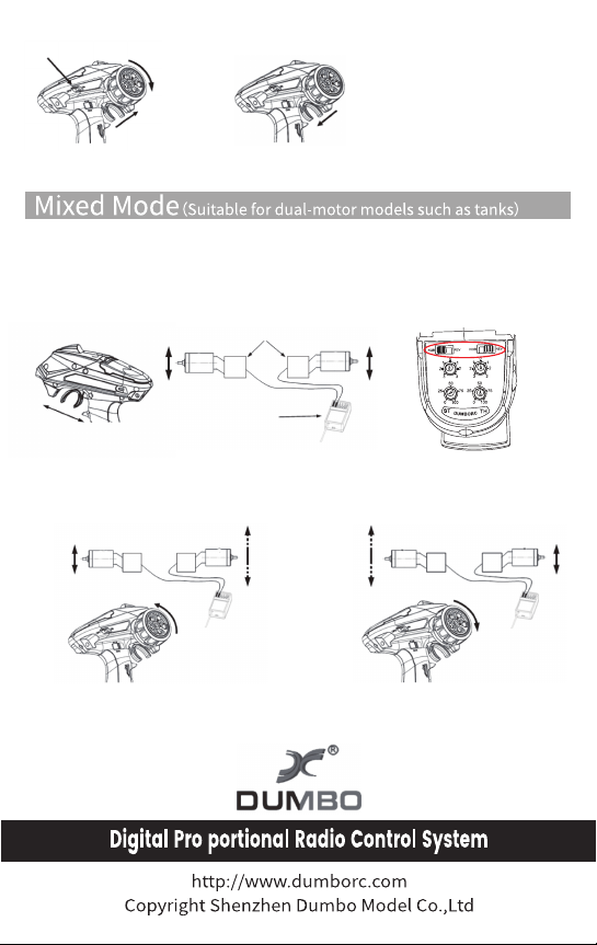
ESC
Motor
Receiver
Motor
2.Turn on
1.Turn the wheel and
trigger forward to the
maximum at the same time
3.After the LED light flashes, pull
the trigger backward to the
maximum. Release the trigger
after the LED light changes color.
Motor positive and negative switch
Connect the two ESC signal lines to the Channel 1 and Channel 2 of the receiver. Under the
mixed mode, the trigger moves backward and forward to control the rotation of the two
motors. The positive and negative rotation of the motor can be set through the two positive
and negative switches on the control panel.
In the mixed mode, the RC model moves forward at a certain speed. At this time, the speed of the
two motors can be adjusted by channel 1 directional wheel to realize left and right differential
steering.
In the mixed control mode, the channel 1 and channel 2 pass forward and reverse direction,
neutral point and motor range can be set separately.
Table of contents
Popular Controllers manuals by other brands

Digiplex
Digiplex DGP-848 Programming guide

YASKAWA
YASKAWA SGM series user manual

Sinope
Sinope Calypso RM3500ZB installation guide

Isimet
Isimet DLA Series Style 2 Installation, Operations, Start-up and Maintenance Instructions

LSIS
LSIS sv-ip5a user manual

Rockwell Automation
Rockwell Automation 1769-L31 installation instructions


