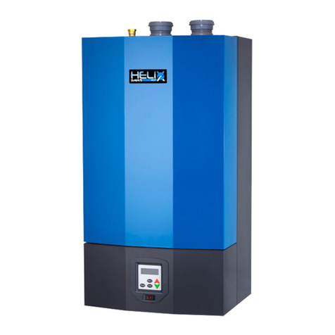
Dunkirk DPFO-3T Technical Document
Other Dunkirk Boiler manuals
Dunkirk
Dunkirk Q95M-200 Instruction manual

Dunkirk
Dunkirk EMPIRE 3EWC0.80 Instruction manual

Dunkirk
Dunkirk XEB-2 User manual

Dunkirk
Dunkirk 95M-200 User manual
Dunkirk
Dunkirk ESC-3090S Instruction manual

Dunkirk
Dunkirk DCBF-125 Instruction manual
Dunkirk
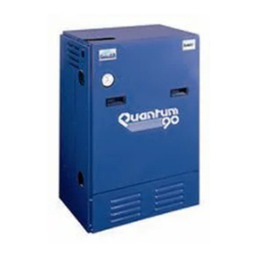
Dunkirk D248 Series Owner's manual
Dunkirk
Dunkirk 90-50 Instruction manual

Dunkirk
Dunkirk DMG-240 Instruction manual

Dunkirk
Dunkirk Q90-50 Instruction manual

Dunkirk
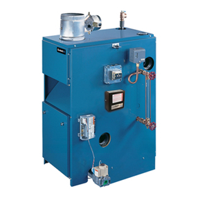
Dunkirk 95M-200 User manual
Dunkirk
Dunkirk PVSB User manual

Dunkirk
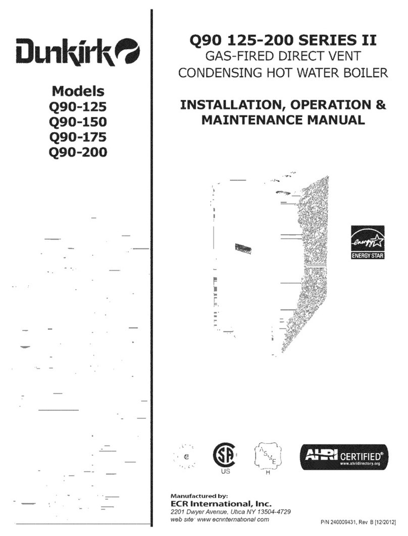
Dunkirk DCC-150 Guide
Dunkirk
Dunkirk Q90 Series II Instruction manual

Dunkirk
Dunkirk Q90-200 Instruction manual

Dunkirk
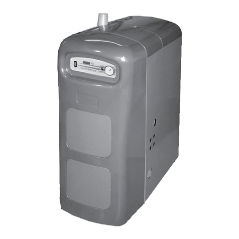
Dunkirk 95M-200 User manual
Dunkirk
Dunkirk Q95M-200 Owner's manual

Dunkirk
Dunkirk DXL-125 User manual
Dunkirk
Dunkirk ESB0365 Technical Document

Dunkirk
Dunkirk DKVLT-050 Instruction manual
Popular Boiler manuals by other brands

IDEAL
IDEAL IMAX XTRA EL 320 user guide

UTICA BOILERS
UTICA BOILERS BC3D Installation, operation & maintenance manual

Lochinvar
Lochinvar SOLUTION 260000 Installation & service manual

Weil-McLain
Weil-McLain EG 6 Series manual

RBI
RBI LCD Series Installation & operation manual

Baxi
Baxi MainEco Combi 28 Installation and service manual

Unical
Unical ALKON R 24 Installation and Servicing Manual

Automatic Heating
Automatic Heating Gasogen Installation and Servicing Manual

Viessmann
Viessmann VITORADIAL 300-T Type VR3 Service instructions for contractors

Alpha
Alpha GasSaver GS-1 Installation and servicing instructions

Baxi
Baxi ROCA LAURA PLUS 28/28 Operating, cleaning and maintenance instructions for the user

Vaillant
Vaillant uniSTOR VIH SW GB 500 BES operating instructions

Kärcher
Kärcher HWE 4000 Gas manual

Radijator
Radijator BIO max 23.1 instruction manual

Granby
Granby BKC Installation, operation and maintenance manual

Brunner
Brunner BSV 20 Instructions for use

Potterton
Potterton 50e Installation and Servicing Manual

UTICA BOILERS
UTICA BOILERS TriFire Assembly instructions


