5
3308120.XXX GENESIS AIR FILTRATION SYSTEM
D. REGISTERREQUIREMENTSASFOLLOWS:
Min. Max.
1. Distancefrom Duct End 5" 8'
2. Distancefrom End ofElbow 15" —
3. DistancebetweenRegisters 24” —
4. TotalNumberRequired 8 12
5. Min.No.requiredperRun 2 —
6. Min.FreeAreaperRegister 14 sq. in. —
E. The Duct material must meet or exceed any agency
or RVIA Standard that may be in existence at the
time the RV is produced.
F. All Discharge Air Ducts must be properly insulated to
preventcondensationfromformingontheirsurfacesor
adjacentsurfacesduringoperationoftheairconditioner/
heat pump. This insulation must be R-7 minimum.
G. Ducts and their joints must be insulated and sealed to
preventcondensationfromformingonadjacentsurfaces
duringoperationoftheairconditioner/heatpump.
4. AIR DISTRIBUTION SYSTEM
INSTALLATION
Dometic Corporation recommends the basic configuration
showninFIG.1for installingthisairconditioner/heatpump
system. We have found by testing, that this configuration
works best in most applications of this air conditioner/heat
pump system.
ItistheresponsibilityoftheInstallerofthissystemtoreview
eachRVfloorplananddeterminethefollowing:
A. Duct size
B. Duct layout
C. Registersize
D. Registerlocations
E. Thermostatlocation.
TheseitemsmustbedeterminedinconjunctionwiththeAir
DistributionSystemSizingandDesignRequirementslisted
in Section 3 of this manual.
Important: Alternate configurations and methods
may be used which still allow the air conditioner/heat
pump to operate properly. However, these alternate
configurations and methods must be approved by
Dometic Corporation in writing.
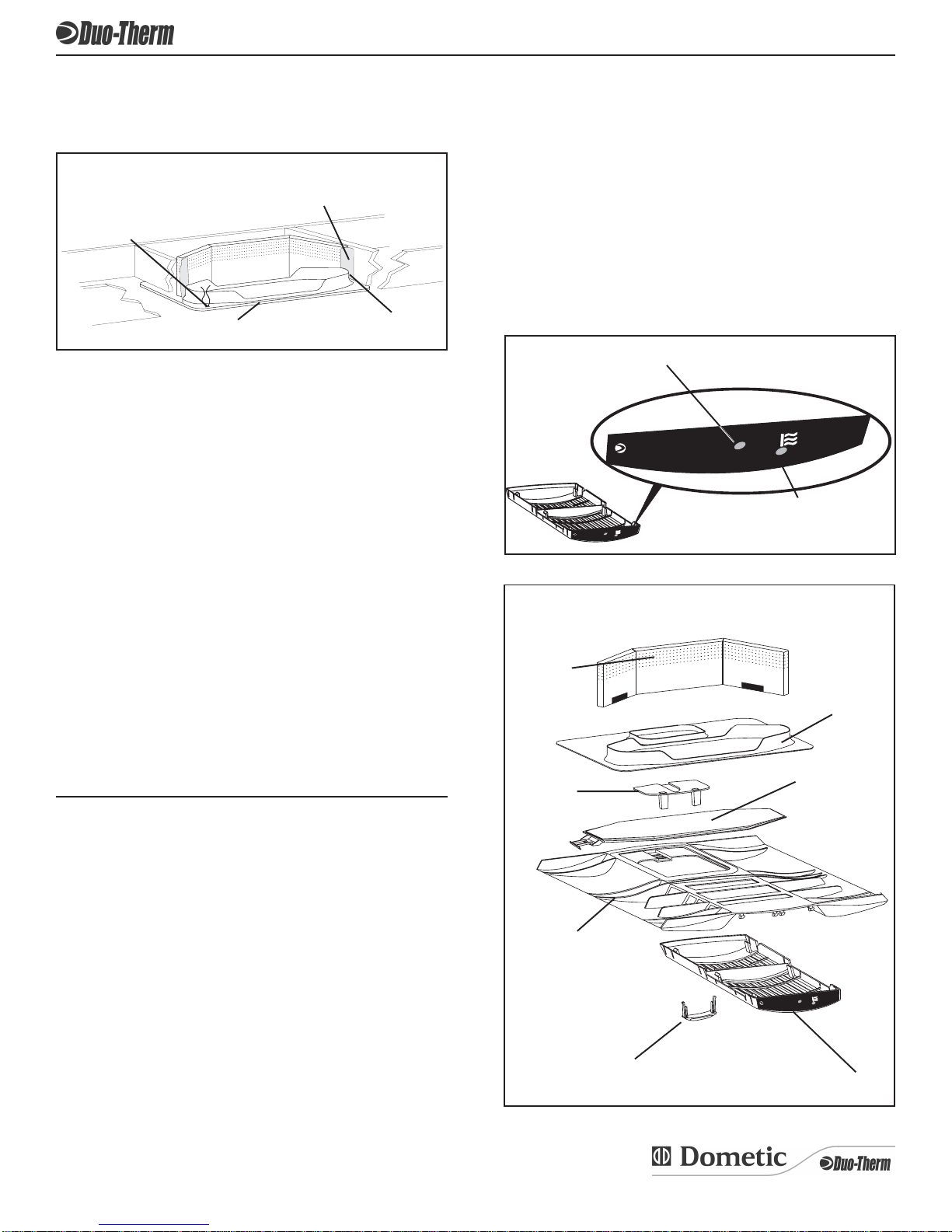
The following instructions are based upon the use of
DometicGenesisAirFiltrationSystemNo.3308120.XXX.
A. Beforepreparingtheceilingopening,thetypeofsystem
optionsmustbedecidedupon.Readalloftheinstruc-
tions packaged with the system options before
beginning the installation.
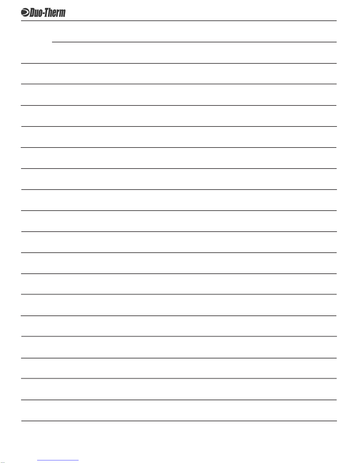
B. ROOFANDCEILINGOPENINGPREPARATION
1. A 14-1/4" x 14-1/4" (±1/8") opening must be cut
throughtheroofandceilingof the RV. This opening
mustbelocatedbetweentheroofandreinforcing
members.
C. DUCTSIZINGREQUIREMENTSASFOLLOWS:
NOTE: Duct sizes listed are inside dimensions.
Min. Max.
1. DuctDepth 2.00" 2-1/2"
2. Duct Width 8.00" 10.00"
3. TotalDuctLength 15' 40'
4. DuctLength (ShortRun) 1/3TotalLength
CENTER DUCT (Penguin 620 & 630 Series Only
Controls In Roof Package)Min. Max.
1. DuctDepth 2.00" 2.00"
2. Duct Width 8.00" 8.00"
3. TotalDuctLength 15' 40'
4. DuctLength (ShortRun) 1/3TotalLength
H. Return Air to the air conditioner/heat pump must be
filtered to prevent dirt accumulation on air conditioner/
heatpumpcoolingsurface.
I. Total System Static Air Pressure
This is to be determined with the air conditioner/heat
pumpbloweroperatingonHighSpeedandreturnairfilter
and grill in place. It is measured in inches of water
Column.
0.55 - 0.90 In. W.C. 579 Series
0.40 - 1.10 In. W.C. 590, 591, 595 Series
0.12 - 0.65 In. W.C. 600, 630 Series
It is the responsibility of the installer to in-
sure the ductwork will not collapse or bend
during and after the installation. Dometic
Corporation will not be liable for roof struc-
tural or ceiling damage due to improperly
insulated, sealed or collapsed ductwork.
CAUTION
2.Marka14-1/4"x14-1/4"(±1/8")squareontheroofand
carefullycuttheopening.
3. Using the roof opening as a guide, cut the matching
hole in the ceiling.
4. The opening created must be framed and sealed to
provideadequatesupportandpreventairfrombeing
drawn from the roof cavity. Lumber 3/4" or more in
thicknessmust be used. Remember to provide an
entranceholeforpowersuppliesandsystemwiresas
needed.
There may be electrical wiring between the
roof and the ceiling. Disconnect 115 volt AC
power cord and the positive (+) 12 volt DC
terminal at the supply battery. Failure to fol-
low this instruction may create a shock haz-
ard causing death or severe personal injury.