DURAG D-FL 200 User manual

07/00 Rev. 6
DURAG
Industrie Elektronik GmbH & Co KG
Kollaustraße 105 · D-22453 Hamburg · Tel. +49 40 554218-0 · Fax +49 40 584154
D-FL 200
Ultrasonic Flow Monitor

D-FL 200 / Rev. 6
______________________________________________________________________________________________________
Industrie Elektronik GmbH & Co KG
Table of Contents
1. Application.........................................................................................................................................1
2. Function .............................................................................................................................................1
3. System Components.........................................................................................................................6
3.1. Evaluation Unit D-FL 200-10......................................................................................................7
3.2. Transducer.................................................................................................................................8
3.3. Purge Air System........................................................................................................................9
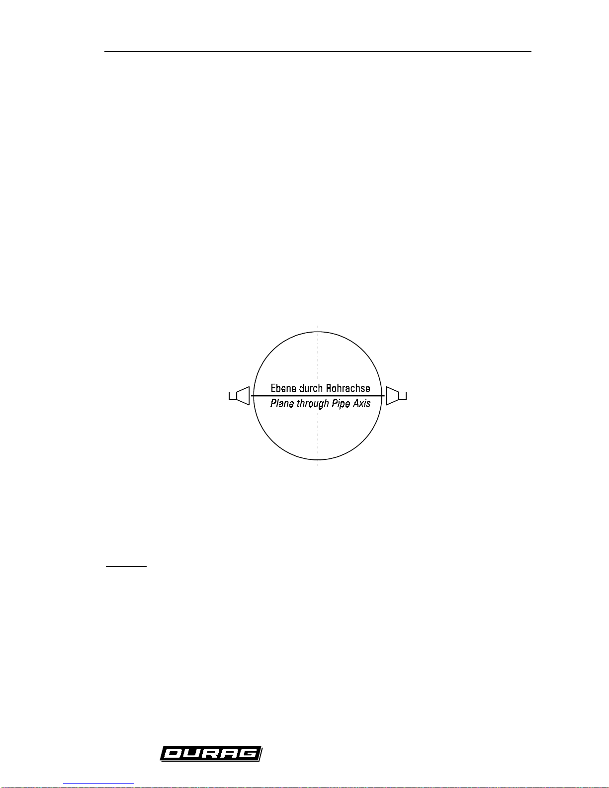
4. Choosing the Measuring Point ......................................................................................................12
5. Electrical Connection D-FL 200......................................................................................................13
5.1. Electrical Connection of the D-FL200-10 Evaluation Unit ........................................................13
5.2. Electrical Connection of the D-FL200-20 Transducers ............................................................15
6. Measuring Sequence.......................................................................................................................16
6.1. Self-Check................................................................................................................................16
6.2. Calibration Cycle....................................................................................................................16
6.2.1. Zero Test......................................................................................................................16
6.2.2. Span Test.....................................................................................................................16
6.3. Monitoring.................................................................................................................................16
7. Registration of Measured Values...................................................................................................16
8. Operating the D-FL 200-10 Evaluation Unit ..................................................................................17
8.1. Key Functions21
8.2. Storing / Entering Parameters by using the Keys....................................................................21
8.3. Storing / Entering Parameters via the RS232 Interface..........................................................21
9. Installation.........................................................................................................................................22
9.1. Mounting the Welding Flanges..................................................................................................22
9.2. Installation of the purge air system...........................................................................................23
9.3. Installation of the sensor units D-FL 200-MK...........................................................................23
9.4. Installation of the evaluation unit D-FL 200-10.........................................................................23
9.5. Start up of the evaluation unit D-FL 200-10..............................................................................24
10. PC-Parameterisation of the D-FL 200COM..................................................................................25
10.1. Installation of the program......................................................................................................25
10.2. Connecting the D-FL 200 system and the PC........................................................................25
10.3. Parameterisation Program D-FL 200COM.............................................................................25
10.3.1. First Page / Main........................................................................................................25
10.3.2. Second Page / Parameter..........................................................................................26
10.3.3. Third Page / Measuring..............................................................................................29
10.3.4. Fourth Page / Signal...................................................................................................31
11. Error Messages..............................................................................................................................32
12. High temperature applications......................................................................................................33
13. Maintenance....................................................................................................................................34
14. Scope of delivery / standard system............................................................................................35
15. Technical Data ...............................................................................................................................38
Transducers .....................................................................................................................................38
Purge air unit “G” for gas above dew point.......................................................................................39
16. Measuring Point Questionnaire ...................................................................................................40

D-FL 200 / Rev. 6
______________________________________________________________________________________________________
Industrie Elektronik GmbH & Co KG
Illustrations
(Fig. 1) Measuring principle.....................................................................................................................2
(Fig. 2) Plane through the pipe axis (standard) .......................................................................................3
(Fig. 3) Consideration of the flow profiles................................................................................................4
(Fig. 4) Measurement independent of the flow profile (optional).............................................................4
(Fig. 5) System components....................................................................................................................6
(Fig. 6) Basic diagram of the microprocessor unit...................................................................................7
(Fig. 7) Dimensions of the D-FL 200-10 evaluation unit..........................................................................8
(Fig. 8) Dimensional drawing of the transducer.......................................................................................8
(Fig. 9) D-FL 200 flange ..........................................................................................................................9
(Fig. 10) Electrical connection of the purge air system..........................................................................10
(Fig. 11) Electrical connection 3-phase power supply 230V..................................................................10
(Fig. 12) Electrical connection 3-phase power supply 400V..................................................................11
(Fig. 13) Dimensional drawing of the purge air system.........................................................................11
(Fig. 14) Measurement in a plane through the pipe axis, standard.......................................................12
(Fig. 15) Measurement in two planes offset from the pipe axis, optional..............................................13
(Fig. 16) Terminal strip on the housing..................................................................................................14
(Fig. 17) Layout of the transducer plug..................................................................................................15
(Fig. 18) Layout of the terminal strip on the sensor board.....................................................................15
(Fig. 19) Front panel of the D-FL 200-10 evaluation unit.......................................................................17
(Fig. 20) Recommended installation of the D-FL 200 welding flanges..................................................22
(Fig. 21) Recommended installation of the D-FL 200 welding flanges..................................................23
(Fig. 22) First page / Main .....................................................................................................................26
(Fig. 23) Second page / Parameter.......................................................................................................27
(Fig. 24) Third page / Measuring...........................................................................................................30
(Fig. 25) Fourth page / Signal................................................................................................................31
(Fig. 26) Measuring in high temperature applications ............................................................................34
Revision : 6
Document : D-FL200-e.doc
Issue : July-2000
Software : FL1.4 or higher
Print date : 31 July 2000

D-FL 200 / Rev. 6 1
______________________________________________________________________________________________________
Industrie Elektronik GmbH & Co KG
1. Application
Acoustic methods of flow measurement use sound waves to determine velocity and flow. The pulse
differential method is among the best known and reliable of such methods. High resolution is achieved
using frequencies in the ultrasonic range.
This monitoring system is applicable in acquiring flue gas volumetric flow in combustion or waste
incineration systems. The system also allows measurements to be made that are otherwise poorly
performed using traditional systems. Measurements in lower velocity ranges are also possible, in
contrast to differential pressure methods. This system is especially advantageous due to its ease of
installation, even on stacks that are wide in diameter.
Acquisition of volumetric flow occurs along the entire profile of the flow. The essential advantage of an
ultrasonic monitoring system is that neither temperature, pressure nor density changes will influence
the measured result. If you want receive the standard volumetric flow you have to consider these three
parameters.
The system is designed for velocities of 0-40 m/s (0-131 ft/sec.) and stack diameters till 5 m (197 in.)
with it measurements up to 0-5,000,000 m³/h (0-approx. 17,7*107ft3/h) are possible.
2. Function
The measurement of volumetric flow using ultrasonic probes offers great advantages compared to
conventional methods using differential pressure, since this type of system operates with no moving
parts. Conventional screens heavily choke the overall flow and cause pressure losses. This causes
high energy costs. The employment of dynamic pressure probes requires the use of expensive special
materials if the stack gas is heavily corrosive. In contrast, purge air is used to separate ultrasonic
sensors from the stack gas.
The monitoring system operates using two ultrasonic transducers, which can both transmit and receive
acoustic signals. These transducers are installed in a stack such that the velocity of the acoustic signal
is influenced by the gas flow. That is to say, the gas flow must show properties of a vectorial portion in
the direction of the acoustic signal (see
(Fig. 1) Measuring principle
). The ultrasonic sensors are
installed at an angle of about 45° (range 30° - 60°) to the axis of the stack. The transit times of the
acoustic impulses form the basis of the volumetric flow and velocity calculations.
(Fig. 1) Measuring
principle
offers a schematic of the monitoring system. The transmitting oscillator receives a keyed
sinusoidal signal and transforms it into an acoustic wave pack whose transit time through the gas
medium is measured. The transit times result as follows:
+=+⋅
tL
(c v cos )
α
Equation 1
−=⋅
tL
(c- v cos )
α
Equation 2
with: t+Impulse transit time with the flow
t
-Impulse transit time against the flow
c Sonic velocity

D-FL 200 / Rev. 6 2
______________________________________________________________________________________________________
Industrie Elektronik GmbH & Co KG
v Gas velocity
L Measuring path in the medium
αAngle of installation
(Fig. 1) Measuring principle
The two equations shown before for impulse transit times may be reduced down for sonic velocity ‘c’
and gas velocity ‘v’:
cL
2tt
tt
=⋅+
⋅
−+
−+
Equation 3
vL
2cos tt
tt
=⋅⋅+
⋅
−+
−+
α
Equation 4
The speed of the sound changes with the temperature of the gas according to the next formula.
whereby T is in Kelvin. With this equation the gas temperature can be obtained from the measurement.
K
T
273s
m
331,6c ⋅=
Gl.5

D-FL 200 / Rev. 6 3
______________________________________________________________________________________________________
Industrie Elektronik GmbH & Co KG
Volumetric flow may be obtained using the following formula:
QkAv=⋅⋅ Equation 6
with: K Correction factor
A Stack diameter
Since each stack develops its own particular velocity distribution, the mean velocity is determined for
calculation of the volumetric flow. If the flow were completely laminar, a single spot measurement
would suffice. The acoustic impulse method enables a cross-sectional measurement to be made over
the entire diameter of the stack. If the ultrasonic sensors are arranged in a plane through a pipe axis,
as shown in
(Fig. 2) Plane through the pipe axis (standard)
, the measured velocity must be weighted
according to the geometry of the pipe.
(Fig. 2) Plane through the pipe axis (standard)
If flow velocity lies in the lower range, the correction factor is 0.75 for cylindrical stacks and 0.66 for
square stacks. If it is technically feasible to do so, a calibration should be performed in such an
installation.
Optional:
An alternative installation is one in which the ultrasonic transducers are installed in one or two planes
which do not run through the pipe axis. This arrangement is shown in
(Fig. 4) Measurement
independent of the flow profile (optional).
This setup is advantageous since the influence of the flow
profile on the measured result is minimized. This is shown schematically in
(Fig. 3) Consideration of
the flow profiles
. The measuring planes must lie in zones which intersect the variable velocity curves.

D-FL 200 / Rev. 6 4
______________________________________________________________________________________________________
Industrie Elektronik GmbH & Co KG
(Fig. 3) Consideration of the flow profiles
(Fig. 4) Measurement independent of the flow profile (optional)
As shown in
(Fig. 4) Measurement independent of the flow profile (optional)
the measuring planes
must be arranged at a distance of r = 0.5774*R from the pipe axis. The correction factor is k=1.
The volumetric flow is determined using four ultrasonic transducers in two planes:
QkA
(v1 v2)
2
=⋅⋅ +
Equation 7
If only two ultrasonic transducers are used in a plane offset from the pipe axis, the volumetric flow is
determined as follows:
QkAv1
=⋅⋅ Equation 8

D-FL 200 / Rev. 6 5
______________________________________________________________________________________________________
Industrie Elektronik GmbH & Co KG
In general, the measurement should result in the standard volumetric flow. This requires the following
conversion:
QQ
P
PT
T
nn
n
=⋅ ⋅
Equation 9
with: P Absolute pressure [hPa]
P
nStandard pressure = 1013 hPa
T Temperature [K]
T
nStandard temperature [K]

D-FL 200 / Rev. 6 6
______________________________________________________________________________________________________
Industrie Elektronik GmbH & Co KG
3. System Components
The D-FL 200 Ultrasonic Flow Monitor consists of the following components:
• D-FL 200-10 evaluation unit
• two or (optional) four D-FL200-MK ultrasonic transducers
• purge air unit
• temperature measurement (optional)
• absolute pressure measurement (optional)
(Fi g. 5) System components

D-FL 200 / Rev. 6 7
______________________________________________________________________________________________________
Industrie Elektronik GmbH & Co KG
Temperature and absolute pressure measurements are required for converting the volumetric flow to
standard volumetric flow. Alternatively these quantities can be programmed into the evaluation unit as
constants. Two 4-20 mA inputs for absolute pressure and temperature measurements are provided in
the evaluation unit. Existing equipment can simply be looped in.
The ultrasonic sensors do not come into contact with the stack gas. In particular, the build-up of
condensate is prevented. The purge air system is specially designed for this and has a negligible effect
on the ultrasonic signal.
The transducers are exclusively supplied with auxiliary power from the evaluation unit. The
piezoelectric ultrasonic sensors are ruggedly built and are designed to withstand environmental
conditions.
3.1. Evaluation Unit D-FL 200-10
Two or (optional) four transducers may be connected to the evaluation unit. The block diagram below
depicts the operations of the unit.
(Fig. 6) Basic diagram of the microprocessor unit
1. Drive sensors
2. Sensor signal amplification
3. Auxiliary power for the transducers
4. Algorithms for assessment of measured values
5. RS232 interface
6. Display output function
7. mA inputs
8. Field bus communications interface (optional)
9. Limit value and state contacts
10.mA outputs

D-FL 200 / Rev. 6 8
______________________________________________________________________________________________________
Industrie Elektronik GmbH & Co KG
(Fig. 7) Dimensions of the D-FL 200-10 evaluation unit
3.2. Transducer
The transducer consists of the ultrasonic sensor, sensor electronics and welding flange.
(Fig. 8) Dimensional drawing of the transducer

D-FL 200 / Rev. 6 9
______________________________________________________________________________________________________
Industrie Elektronik GmbH & Co KG
(Fig. 9) D-FL 200 flange
The required minimum length of the welding flanges can be obtained from the next equation:
L(20 D 150 cos )
sin
W
=++⋅
α
α
Equation 9
with: L Length of the flanges [mm]
D
W Wall thickness of the duct [mm]
3.3. Purge Air System
The use of a purge air system helps to prevent the surfaces from getting dirty prematurely and also
protect the system against the heat of the flue gas. If a purge air system is not used, the monitoring
system may suffer from excessive dirt accumulation in applications where negative pressure is
prevalent. This is especially true if the boiler is shut down, absence of an upward draft and during start-
up phase.
The following points should be considered when selecting a location to mount the purge air system:
• The intake air must be as dry and dust-free as possible.
• The temperature of the intake air may be a maximum of 313 K (104°F/40°C).
• When mounting the system, the filter has to be vertical. The dust valve must situated at the
bottom.
• Adequate space must be left for exchanging the filter (see page 11).
If the purge air system is being mounted outdoors, the weather hood D-WSH 290 GN is available.

D-FL 200 / Rev. 6 10
______________________________________________________________________________________________________
Industrie Elektronik GmbH & Co KG
Caution! The following must be observed during the electrical installation of the
D-FL 200:
• The installation may be done only by a skilled worker.
• Before performing any work on the system, it must be disconnected from the power supply.
• The power supply and frequency has to correspond with the information shown on the nameplate.
• Connections must be made as shown on the wiring diagram on the cover of the terminal strip.
• The grounded lead must be connected to the ground terminal.
• The motor safety switch (not included) must be set to the rated current of the motor.
• The direction of rotation of the motor must be checked (Arrow on the cover).
• Ensure a separate power supply for the purge air system, because the purge air has to blow all
the time.
Use the wiring diagram as shown in
(Fig. 10) Electrical connection of the purge air system
if your
power supply is single phase. In the case of using three-phase power supply you must connect your
motor according to
(Fig. 11) Electrical connection 3-phase power supply 230V
and
(Fig. 12) Electrical
connection 3-phase power supply 400V.
Use
Fig. 11
if you supply with 200V - 240V. If you supply with
345V - 415V than connect the motor according to
Fig. 12.
Erde
Ground
(Fig. 10) Electrical connection of the purge air system
Erde
Ground
(Fig. 11) Electrical connection 3-phase power supply 230V

D-FL 200 / Rev. 6 11
______________________________________________________________________________________________________
Industrie Elektronik GmbH & Co KG
Erde
Ground
(Fig. 12) Electrical connection 3-phase power supply 400V
(Fig. 13) Dimensional drawing of the purge air system

D-FL 200 / Rev. 6 12
______________________________________________________________________________________________________
Industrie Elektronik GmbH & Co KG
4. Choosing the Measuring Point
The technical conditions found in different stacks, boilers or filtering systems vary greatly. In principle, it
is advisable to have a qualified independent agency (e.g., TÜV) make the determination. One must
observe, however, that the most symmetrical flow profile possible is present at the measuring point.
There must also be enough space available to install the purge air system and evaluation unit.
The flow paths (length of stack) ahead of and after the measuring point should be at least 3D (D =
interior diameter of the stack). If using four transducers, the flow paths may, if necessary, be less than
3D. This should only be done, however, in consultation with the independent agency mentioned above.
The measuring point should not only be safely accessible for start-up and calibration procedures, but
also for any necessary future maintenance.
The measuring path should, if possible, be set up at an angle of 45°. If the interior diameter of the
stack is very great, the equipment may be installed at a flatter angle. According to the flow direction
the angle should be at the very most 60°. Also, the maximum measuring path length for the acoustic
signals may not be exceeded:
Maximum measuring path length, standard flue gas
Temperature Measuring head 1
(50 kHz)
Measuring head 2
(41 kHz)
Measuring head 3
(30 kHz)
up to 80°C / 176°F 5m / 197 in 8m / 315 in 11m / 433 in
up to 120°C / 248°F 4m / 157 in 6,5m / 256 in 8,0m / 315 in
up to 160°C / 320°F 3m / 118 in 5m / 197 in 6m / 236 in
more than
160°C / 320°F
2m / 79 in 3,5m / 138 in 4,5m / 177 in
For stacks with a small interior diameter, it is recommended that the measuring heads be installed at a
smaller angle (min. 30°) concerning to the gas flow, since this increases the resolution. The minimum
measuring path length is 2 m/ 6.6ft. The angle is flexible enough that one can consider a working
platform, etc.
As already discussed in the section
2. Function, page 1
several installations are possible:
(Fig. 14) Measurement in a plane through the pipe axis, standard

D-FL 200 / Rev. 6 13
______________________________________________________________________________________________________
Industrie Elektronik GmbH & Co KG
(Fig. 15) Measurement in two planes offset from the pipe axis, optional
Ultrasonic transducers are frequently installed as shown in
(Fig. 14) Measurement in a plane through
the pipe axis
because it is less expensive. However, an installation of transducers in two planes can
certainly be carried out, as shown in
(Fig. 15) Measurement in two planes offset from the pipe axis
.
The correction factors, which you can find in section
2. Function, page 1,
have to be programmed into
the evaluation unit.
The handling of this evaluation unit is explained in section
8. Operating the D-FL 200-10 Evaluation
Unit
. The correction factors can be improved by parallel measurements of an independent agency if
necessary.
If the duct runs horizontally, the transducers may be installed in a horizontal plane. If the transducers
are installed in a vertical plane, the lower sensor will more easily accumulate condensate and dust.
5. Electrical Connection D-FL 200
5.1. Electrical Connection of the D-FL200-10 Evaluation Unit
The D-FL200-10 evaluation unit is manufactured as a 19” module. Since the evaluation unit is to be
mounted as close to the transducers as possible, an IP 65 / NEMA 4X housing is supplied. The layout
of the terminal strip on the housing is depicted in
(Fig. 16) Terminal strip on the
housing
.
The
transducers are connected to the evaluation unit with specially shielded cable. The maximum
permissible cable length from the transducers to the evaluation unit is 50 m / approx. 164 ft.

D-FL 200 / Rev. 6 14
______________________________________________________________________________________________________
Industrie Elektronik GmbH & Co KG
(Fig. 16) Terminal strip on the housing

D-FL 200 / Rev. 6 15
______________________________________________________________________________________________________
Industrie Elektronik GmbH & Co KG
5.2. Electrical Connection of the D-FL200-20 Transducers
The transducers are delivered with a plug connection. The terminal layout is shown in
(Fig. 17) Layout
of the transducer plug
.
(Fig. 17) Layout of the transducer plug
The sensor electronics are located in the transducer, along with a terminal strip. This terminal strip was
wired to the plug at the factory. The pin-out of this connector is shown in
(Fig. 18) Layout of the
terminal strip on the sensor board.
(Fig. 18) Layout of the terminal strip on the sensor board

D-FL 200 / Rev. 6 16
______________________________________________________________________________________________________
Industrie Elektronik GmbH & Co KG
6. Measuring Sequence
6.1. Self-Check
The evaluation unit performs a self-check upon power-up. The display will indicate “Self-Check”
throughout the duration of the test and the relay contact "Maintenance“ is in operation.
6.2. Calibration Cycle
After the self-check a calibration cycle is performed for 4 minutes. The calibration
cycle consists of a ‘zero test’ and ‘span test’. This cycle is performed according to the
time interval programmed in program mode2 (standard every 24h). The state output
contact “Maintenance” is contacted during this period.
Unaffected of this two calibration tests an automatic check cycle is performed. This
automatic check cycle inspects the right operation of the electronic parts. It takes
place beside the permanent measuring cycle.
6.2.1. Zero Test
After the sensor check, a zero test is performed for two minutes. Each sensor
transmits two brief impulses, which are received by the opposite sensor. This
sequence is repeated in both directions. The zero point is checked using the
evaluation formulas noted above.
6.2.2. Span Test
During the span test, staggered signals are transmitted and received. Using the
evaluation formulas, the reference point can be checked.
6.3. Monitoring
The system automatically begins monitoring after the calibration cycle. The state
output contact “Maintenance” changes from the position “ON” to “OFF”.
7. Registration of Measured Values
The D-FL 200-10 is equipped with two mA outputs. The standard volumetric flow is given to output 1,
and the gas velocity is given to output 2.
For continuous registration of measured values, strip chart recorders (0-20 mA) with a printing width of
at least 100 mm (4 inch) can be used (quality class 1.0, according to VDE 0410. The zero point (live
zero) lies at 20% (4 mA) of scale.
A computerized emissions evaluator may also process the measured values issued.
The integration time (continuous mean value generation) of the measured value can be set in the D-FL
200-10 in one-second steps between 1 and 180 seconds.

D-FL 200 / Rev. 6 17
______________________________________________________________________________________________________
Industrie Elektronik GmbH & Co KG
8. Operating the D-FL 200-10 Evaluation Unit
The parameters can be entered both by pressing the four keys on the front panel as well as via the
RS232 interface.
RS232
(Fig. 19) Front panel of the D-FL 200-10 evaluation unit
The three upper LED’s indicate the following:
LED Display Display Functions
Measuring The system is in measuring-mode
Check Cycle The system is doing a check cycle
Limit Value The limit value is reached
The three lower LED’s indicate the following:
LED Display Display Functions
Display Select Display.
The operator may choose to display the gas velocity, operating volumetric flow,
standard volumetric flow and temperature. Measurement continues when
switching from one display to the next. The “Measurement” state contact is
closed and the “Maintenance”
state contact remains open.
Maintenance The “Maintenance” state contact is closed
Parameterisation Parameterisation
- the “Maintenance” state contact remains closed
- the parameters may be entered using menus on the display
Table of contents
Other DURAG Monitor manuals