4
Technical Specifications
Dimensions: 745mm x 222mm
Reach: 2000mm over
material support capacity
Stand Height (with mounts): 690mm
Maximum Weight Capacity: 227kg
Weight: 10kg
General Safety Instructions for Power Tools
Using power tools of any kind can be dangerous if safe
operating procedures are not followed. Recognizing the
hazards of each tool and using them with respect and
caution will considerably limit the possibility of personal
injury. However, if safety precautions are ignored, personal
injury will likely result. Always use common sense – your
personal safety‑is your responsibility. Know your power tool.
Read and understand the Operator’s Manual and observe
the warnings and instruction labels affixed to the tool.
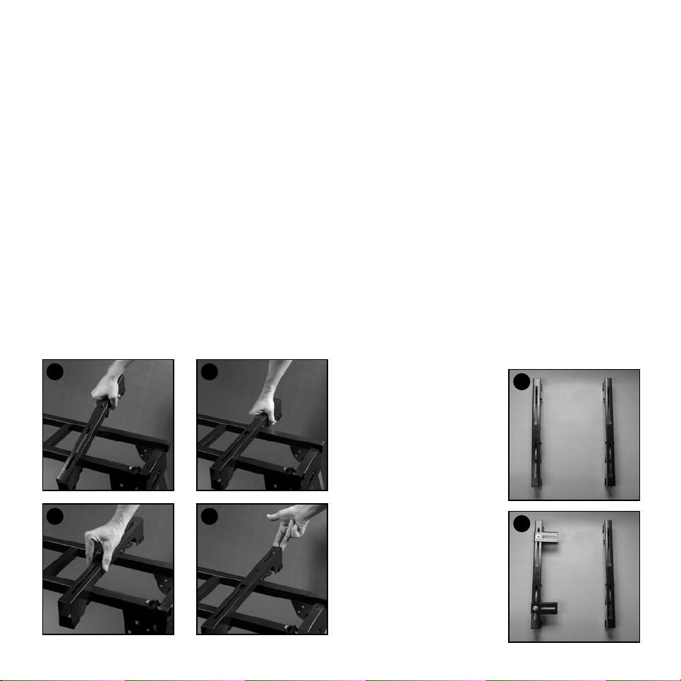
Safety Instructions for Mitre Saw Stands
1. Use caution when folding or unfolding legs to limit any
finger pinch points.
2. Place stand on flat and level surface to keep tool from
rocking or tipping.
3. Make certain that work support extensions are within safe
operating limits, and are properly locked in place before
using tool. Do not exceed 227kgs. on main
frame table.
4. Test the setup for stability before proceeding with work.
5. Be sure the Mitre saw is tightened securely at all
mountings before use.
6. This stand will safely mount most mitres saws (including
slide) of up to and including 10 inch provided the weight
distribution is central and the total loading including work
piece does not exceed the Max weight capacity. For
example, 12” sliding Mitre saws are NOT to be used on
this stand because the weight of the saw in the rear‑most
position can make the stand unbalanced, becoming a
tipping hazard.
7. This product is designed for mounting and supporting a
range of bench top appliances. It is NOT designed for
supporting persons for any reason.
8. Do Not stand, climb, or sit on this product
9. Do Not use for Scaffolding purposes.
10. Do not use the stand with one or more legs not locked
in the down position. All legs must be locked in place as
designed. The ground needs to be flat so all 4 legs are
in contact with the ground surface to ensure stability
Unpacking
Due to modern mass production techniques, it is unlikely
that your Duropro mitre saw stand is faulty or that a part is
missing. If you find anything wrong, do not operate the tool
until the parts have been replaced or the fault has been
rectified. Failure to do so could result in serious
personal injury.
Parts List
• Quick Attach Machine Mounts x 2
• Outrigger Supports x 2
• Work Supports / Tube Supports x 2
• Off Set Mounts x 2
• M8 Locking Knobs x 4
• 8mm x 20 Bolts / Washer & nut x 2
• 8mm x 45 Bolts / washer & nut x 4
• Top stand frame assembly with 4 legs attached
• Wheels x 2