3
Installation
The Dutypoint MiniBreak tank booster set is despatched mounted on a wooden pallet and
covered in a protective film, it is recommended that the unit be retained in the protective
packaging until the product is to be installed. The unit will arrive pre-packaged and wired ready
for installation. This product has been fully run tested at our works under simulated site
conditions. The unit should be thoroughly checked for physical damage that may have been
caused during transit. If the unit is found to have damage it must be reported immediately and
should not be installed.
The unit should be sited in a dry, frost-free environment wall mounted in a position that will
allow adequate room for general maintenance and service.
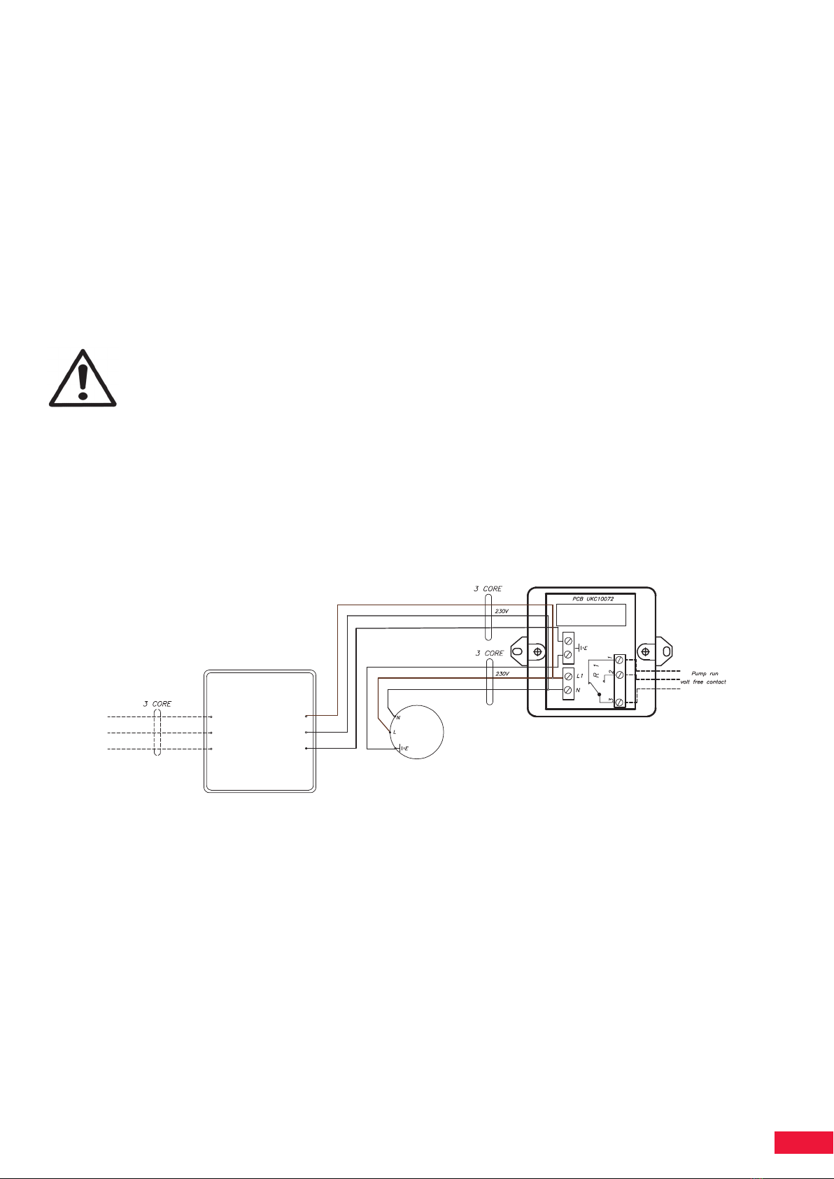
Electrical connections
The cable used for the incoming supply must be of adequate size to carry the motor full load
current. This is shown on the duty plate. A high sensitivity differential switch (0.03A) is also
recommended.
All connections must be made using the appropriate wiring drawings for the equipment being
installed, with particular attention being paid to the supply voltages.
Never operate this product with the pump controller front panel or the motor terminal
cover removed.
It is essential that this equipment is earthed to the building earth system.
Pump operates at 230v 50Hz
The base frame must be earth bonded directly to the building earth system.
The power supply wiring should be arranged such that it enters the enclosure
through appropriate cable gland and then enters the pump controller through its
cable gland.
Water supply and system connection
Connect the Dutypoint MiniBreak tank booster water inlet 15mm compression (left side of
cabinet) to a suitable water supply The inlet should be provided with an isolation valve to aid
maintenance. If the pressure available at the ball valve is below 0.3 bar, a low pressure orifice
must be obtained and fitted.
Extend the 22mm plastic overflow pipe from the left hand side of the unit to a position where
an overflow will be noticed and rectified.
It is the responsibility of the installer to ensure that the overflow is able to keep up with the
incoming water volume, if this is not the case then a pressure reducing valve should be fitted
to reduce the incoming mains water volume
Connect the discharge port 15mm push fit (right hand side of cabinet) to the system inlet.
Draining the break tank can be achieved by isolating the suction line ball valve on the flexible
connector and removing the flexible end attached to the pump, the flexible connector can then
be positioned over a container to collect the drained water.
Inexperienced users
This product must be operated by qualified personnel only.
Be aware of the following precautions:
This product is not to be used by anyone with physical or mental disabilities, or anyone without
the relevant experience and knowledge, unless they have received instructions on using the
equipment and on the associated risk or are supervised by a responsible person.
Children must be supervised to ensure that they do not play on or around the product.