Dutypoint ResiSHIELD DH-W User manual

Operation and Maintenance Manual
Dutypoint ResiSHIELD
Model - DH-W
DOC-RSDHW2306

About us.
Applied knowledge.
Shared know-how.
Fearless innovation.
Together, we are Dutypoint. Since 1976, we’ve been building up industry-defining expertise in fluid
technology.
This knowledge means we solve complex challenges with straightforward solutions that are built
around meeting and exceeding our clients’ needs. We approach everything with the same
philosophy: how will we go above and beyond?
Our commitment to collaboration and sharing knowledge galvanises and cements robust
relationships. Relationships that are built to last, because our clients are our partners.
Our focus for the future? Innovation. We want to be the future of our industry, globally. Where we
benchmark thought leadership, expertise and customer care.
We set the bar.
Contact details.
T: +44(0)1452 300592
Registered Office:
Dutypoint Limited
Quedgeley West Business Park
Bristol Road
Hardwicke
Gloucester
GL2 4PA
United Kingdom

Table of Contents
© 2023 Dutypoint Limited
Dutypoint is a trading name of Dutypoint Limited, a company registered in England and Wales No 9045694
1. Important Safety Information .................................................................................. 4
2.
System Specifications ............................................................................................ 9
4. Installation and Commissioning..............................................................................25
5. Operation and Maintenance....................................................................................28
6. Troubleshooting ..................................................................................................... 29
3. Control Panel Instructions...................................................................................... 15
7. Warranty................................................................................................................. 30
8. Declaration of Conformity........................................................................................31

1. Important Safety Information
4
1. Important Safety Information
1.1 Health & Safety at Work Act 1974
Section 6(a) of this Act requires manufacturers to advise their customers on the safety and the handling
precautions to be observed when installing, operating, maintaining and servicing their products. The user’s
attention is therefore drawn to the following:
• The appropriate sections of this manual must be read before working on the equipment.
• Installation, operating and maintenance must only be carried out by suitably trained/qualified personnel.
• Normal safety precautions must be taken and appropriate procedures observed to avoid accidents.
Refer to Dutypoint for any technical advice or product information. It is the responsibility of the customer and/or
the contractor:
• To ensure that anyone working on the equipment is wearing all necessary protective gear/clothing;
• Is aware of appropriate health & safety warnings and to read the information in this manual.
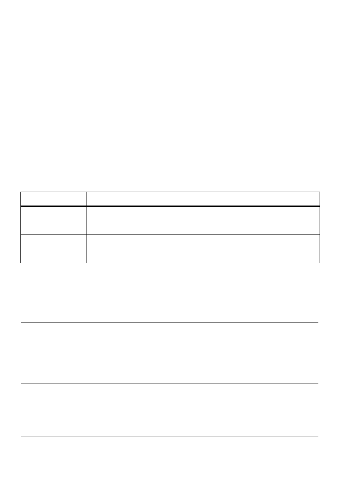
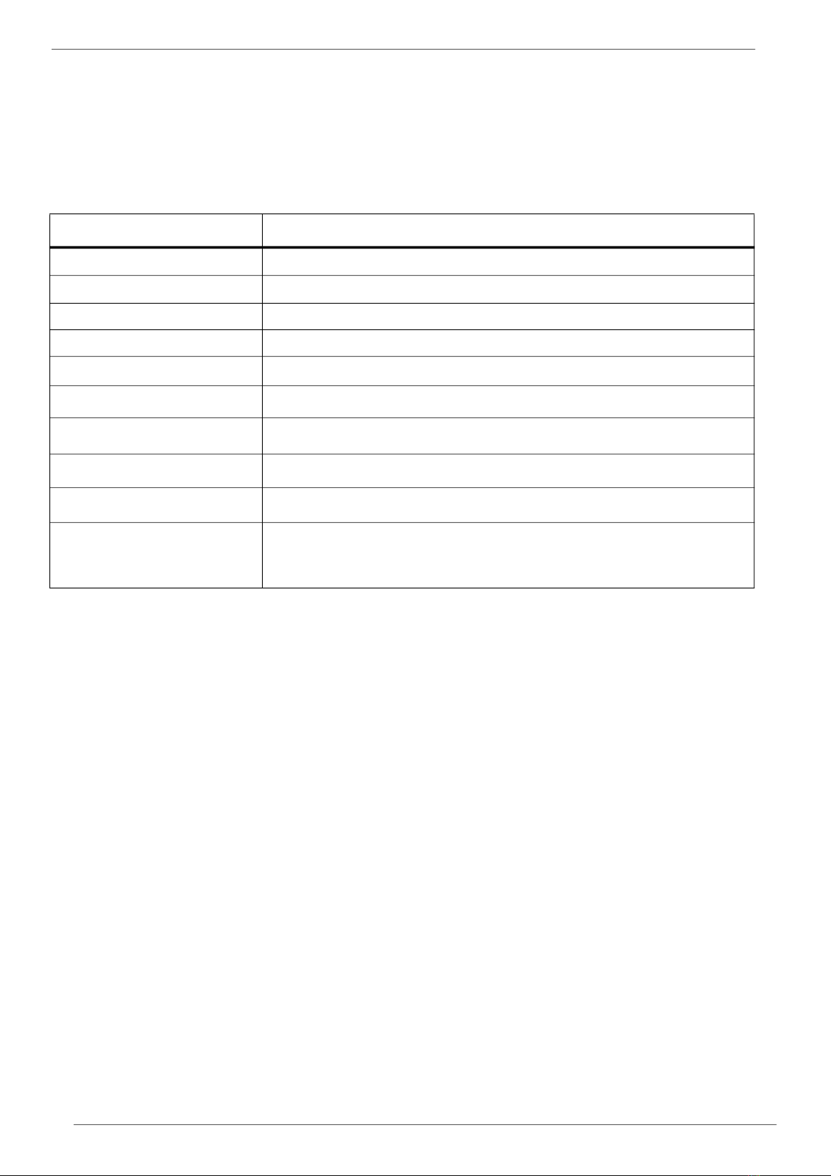
1.2 Safety Messages and Hazard Statement
Table 1.1: Hazard Notice Definitions
1.3 Qualified Personnel
WARNING
This product is intended for operation by qualified personnel only
• Only qualified personnel are allowed to install or operate this equipment
• Qualified personnel are defined as trained staff, who are authorised to install, commission and maintain
equipment, systems and circuits in accordance with relevant laws and regulations. Personnel must be
familiar with the instructions and safety procedures described in this document.
• This product should not be used by anyone with mental disabilities, or anyone without the relevant
experience and knowledge, unless they have received instructions on using the equipment and on the
associated risks, or are supervised by a responsible person.
• Children must be supervised to ensure they do not play on or around the equipment.
1.4 Environmental Protection
All local regulations and codes regarding emissions and waste disposal must be followed. This may include:
• Reporting of emissions to appropriate authorities
Message Level Definition
DANGER A hazardous situation which, if not avoided, will result in death or serious injury
WARNING A hazardous situation which, if not avoided, could result in death or serious injury
CAUTION A hazardous situation which, if not avoided, could result in minor injury
or moderate injury
ELECTRICAL HAZARD Risks associated with electricity will cause hazards if not properly avoided
Note A situation which may arise resulting in undesirable conditions and/or will
not cause direct hazards to persons

1. Important Safety Information
5
• Sorting, recycling and disposal of solid or liquid waste
• Clean-up of spills
• Separate disposal of electrical components from domestic waste
1.5 Mechanical Device Servicing
• Familiarise yourself with the relevant contents of this manual
• Installation, maintenance and repair work must only be carried out by trained, skilled and suitably qualified
personnel.
• Disconnect or lock-out the power source to ensure that the item(s) will remain inoperative. Locking out the
equipment by switching off the release mechanism or set value WILL NOT prevent accidental starting.
• Allow the item(s) to cool if over-heated.
• CLOSE the isolating valves on the suction and discharge connections of the affected item(s).
• If working on pump, VENT slowly and cautiously – Refer to the relevant section of this manual.
• DRAIN the pump(s).
1.6 Pump Hand Control Mode (Where Fitted)
In the 'HAND' position the pump(s) controlled by the switch will normally run at full speed and completely
independently of any control devices, and can result in pump(s) running against a closed valve head if there is no
draw. This can cause the system to be maintained at the maximum pressure produced by the pump plus any
incoming pressure and additional pressure caused by water surge and can potentially damage the pump and
other parts of the system.
The 'HAND' option should only be used with a competent operator in attendance, or when there is a continued
demand sufficient to provide constant flow through the pumps to maintain the running pressure of the system to an
acceptable level.
1.7 Personal Protective Equipment
Use personal safety equipment according to the site conditions and employer regulations. This may include, but
may not be limited to:
• Hard hat
• Safety goggles with side shields
• Protective footwear
• Protective gloves
• Respirator
• Ear protection
• First aid kid
• Safety devices
1.8 Precautions Before Commencing Work
Ensure that the following safety precautions are complied with before commencing work:
•Create a safe working area, and provide a suitable barrier around the work area
• Ensure all safety guards are in place and secure
• Ensure you have a clear path of exit
• Ensure that the product cannot roll or fall over and cause damage to persons or property
• Ensure all lifting equipment is in good condition and rated for the intended task
• Use a lifting harness, safety line and respirator as required
• Allow hot components to cool before handling them
• Ensure that product has been thoroughly cleaned
• Disconnect and lock out power supply, ensuring that it cannot be accidentally re-connected

1. Important Safety Information
6
• Check for any risk of explosion before using hand tools
1.9 Precautions During Work
• Never work alone
• Always wear protective clothing and hand protection
• Stay clear of suspended loads
• Always use appropriate lifting devices
• Beware of risks of sudden starts of any automated equipment such as level control
• Beware of starting jerks of electric motors - these can be powerful
• Do not exceed the stated operating limits of equipment
• Do not remove vent plugs from a pressurised system - ensure pressurised components are relieved of
pressure before disassembly
• Ensure guards are in place during operation
1.10 Hazardous Fluids and Chemicals
If hazardous chemicals come into contact with skin or eyes, use the following procedures:
1.11 Electrical Safety - High Voltages
This information is especially applicable when Variable Speed Controllers (Inverters) are fitted to pumps.
When the inverter variable speed drive head is connected to the power supply the components of the power unit as
well as certain components of the master control unit – are also connected to the power supply.
DANGER!
Touching these components can seriously endanger life!
• Before removing the frequency inverter cover, the system must be disconnected from the power supply
• After switching off the power supply wait at least 5 minutes before starting work on or in the inverter drive
head - the capacitors in the intermediate circuit must be given time to discharge completely via the discharge
restors.
ELECTRICAL HAZARD
Up to 800V can be present - if there are faults this can be higher
• All work carried out when the frequency inverter is open must be performed only by suitably qualified and
properly authorised personnel.
Condition Action
Chemicals or
hazardous fluids
in eyes
1) Hold your eyelids apart forcibly with your fingers
2) Rinse the eyes with eyewash or running water for at least 15 minutes
3) Seek medical attention
Chemicals or
hazardous fluids
on skin
1) Remove contaminated clothing
2) Wash the skin with soap and water for at least 1 minute
3) Seek medical attention

1. Important Safety Information
7
ELECTRICAL HAZARD
THE SYSTEM MUST ONLY BE OPERATED WHEN IT HAS BEEN CORRECTLY EARTHED AND PIPES
BONDED TO EARTH IN ACCORDANCE WITH IEE REGULATIONS
• When connecting external control wires care must be taken not to short circuit adjacent components. Bare
cable ends which are not in use must be insulated.
1.12 Electronic Safety Devices
• Inverter drives contain electronic safety devices which switch off the control element in the event of a fault
developing.
• A motor can also be stopped by ‘mechanical blocking’
• If it is switched off electronically, the motor is disconnected from the mains voltage supply via the electronics
in the inverter drive.
• Voltage fluctuation and power failures (temporary outages) can cause the motor to switch itself off.
WARNING
A motor will have zero current but will remain energised as it stops
• Take necessary precautions - the motor is not voltage-free in the circuit itself
WARNING
Repair of faults can cause items to start up again unexpectedly
Ensure the motor is isolated before commencing any work
WARNING
High voltage tests of inverters may damage the electrical components.
• Bridge before the incoming/outgoing terminals L-L2-L3 and U-V-W.
• To avoid incorrect metering by capacitors incorporated in the electronic circuits, isolate the motor from the
inverter drive head.
1.13 Spare Parts
WARNING
Use of non-genuine spare parts may cause damage to equipment, damage to property and voiding of
warranty
• Use genuine, Dutypoint-approved spare parts only
• If in doubt, contact Dutypoint Service on 01452 300590.

1. Important Safety Information
8
Depending on their characteristics the materials may be recycled. Through recycling and other forms of
processing Waste Electrical and Electronic Equipment, you can make a significant contribution towards helping to
protect the environment.
Please contact your local authorities for information on the collection point nearest you.
1.14 Storage
The product must be stored in a covered and dry location free from heat, dirt and vibrations.
NOTE: Protect the product against humidity, heat sources and mechanical damage
NOTE: Do not place heavy weights on the packed product
1.15 Disposal
At the end of its working life, this product should not be disposed of with standard household waste, but rather
dropped off at a collection point for the disposal of Waste Electrical and Electronic Equipment (WEEE) for recycling.
Figure 1.2: Waste Symbol
This is confirmed by the Waste Symbol found on the product, user manual or packaging.

2. System Specifications
Message Level Definition
Application BS9251:2021 Category 1 Fire Sprinkler Systems
Pumps Dutypoint TH Horizontal Multistage. See p. 12
Duty Flow Range 30 - 200 l/min
Duty head range 1 - 5 bar
Volt Free Contacts -Fire Mode Activated
-Common Fault
9
2. System Specifications
2.1 Range Specifications
Table 2.1: Range Specifications
Liquid temperature range 1-23 °C
Ambient temperature range
Humidity
Controller Type
Maximum System Pressure
5 - 40 °C
Max 50%
Dutypoint Martech WD2
10 Bar

2. System Specifications
2.2 ResiSHIELD Range
Table 2.2: Product Identification
10
-W
-W Denotes that a WD2 type panel has been installed

2. System Specifications
11
2.3 Product Overview
Table 2.2: Product Identification
1. Controller
2. Water Inlet Connection
3. Water Outlet Connection
4. Automatic Test Drain Connection
5. Pressure Gauge
6. Pump
7. Control Panel
8. Pressure Switch
9. Flow Switch
10. Union
11. Non-Return Valve
12. Isolation Valve
13. Manual Flow Test Valve
14. Auto Test Solenoid Valve
15. Strainer
16. Primer Port

2.System Specifications
2.4 Technical Data
Table 2.3 : Range Matrix
Model
DH0302E-MD
DH0303E-MD
DH0304E-MD
DH0305E-MD
DH1004E-MD
DH0502E-MD
DH0503E-MD
DH0504E-MD
DH0505E-MD
DH1002E-MD
DH1005E-MD
Pump
model
TH3/2
TH3/3
TH3/4
TH3/5
TH5/2
TH5/3
TH5/4
TH5/5
TH10/02
TH10/03
TH10/04
Supply
Voltage
200/1/50
200/1/50
200/1/50
200/1/50
200/1/50
200/1/50
200/1/50
200/1/50
200/1/50
200/1/50
200/1/50
Motor
Nominal Power
(P2) kW
0.33
0.45
0.55
0.75
0.55
0.45
0.9
1.1
0.75
1.1
1.5
Motor
Input Power
(P1) kW
0.46
0.6
0.76
0.91
0.81
0.59
1.1
1.32
0.87
1.24
1.7
FLC
(amps)
Suction
Size
(BSP)
Discharge
Size
(BSP)
2.5
3
3.7
4.3
3.9
3
5.3
6.2
4.3
6.3
8.2
1 1/4"
1 1/4"
1 1/4"
1 1/4"
1 1/4"
1 1/4"
1 1/4"
1 1/4"
1 1/4"
1 1/4"
1 1/4"
Recommended
Supply
MCB Type
D6
D6
D6
D6
D6
D6
D10
D10
D6
D10
D16
12
1"
1"
1"
1"
1"
1"
1"
1"
1 1/4"
1 1/4"
1 1/4"

2.System Specifications
13
2.5 Pump Performance Curves
SINGLE PUMP CURVES
Total head (m)
10
0
30
50
60
20
40
0
3
4
8
5
7
6
Flow (litres/minute)
02010 4030 8070 9050 60
Flow (litres/minute)
NPSH (m)
100
02010 4030 8070 9050 60 100
2
1
DH0305
DH0304
DH0303
DH0302
DH03 Series

2. System Specifications
Pump performance curves continued
14
SINGLE PUMP CURVES
Total head (m)
10
0
30
50
60
20
40
0
3
4
8
5
7
6
04020 60 120 14080 100
Flow (litres/minute)
NPSH (m)
160
2
1
04020 60 120 14080 100 160
DH0505
DH0503
DH0502
DH0504
Flow (litres/minute)
DH05 Series

2. System Specifications
15
Pump performance curves continued
DH10 Series
SINGLE PUMP CURVES
Total head (m)
10
0
30
50
20
40
0
3
4
6
5
Flow (litres/minute)
04020 60 220 240
Flow (litres/minute)
NPSH (m)
280
2
1
80 100 120 140 160 180 200 260
04020 60 220 240 28080 100 120 140 160 180 200 260
DH1004
DH1003
DH1002

Operation Manual
Electric Motor Driven Residential Pump
Controller BS9251: 2021
Dutypoint Martech WD2 version
16
3.Control Panel Operation

Dutypoint Martech Fire Sprinkler Controller Installation Guide
This document provides essential information on how to install, configure and test the Dutypoint Martech The
good news is the Dutypoint Martech is easy to install and requires minimum set up and configuration.
Key features:
Input connections for:
•Dual pressure switch (monitored)
•Flow switch (monitored)
•Water level
Output connections for:
•Pump
•Diverter valve
•Fire panel
•Fault monitor
•Low water alarm
USB connection for:
•Uploading of advanced configuration files
•Software updates
Dutypoint Martech has been designed with failsafe
features that help ensure that the pump will run
when the pressure drops (in the event of a
sprinkler head opening) even if the microprocessor
or software fails.
WARNING –Dutypoint Martech is a safety critical
device and MUST be installed by a qualified
electrician/electrical engineer in accordance with
relevant electrical installation regulations and
relevant fire sprinkler regulations.
Failure to install and configure correctly may result
in the fire sprinkler system failing to operate,
resulting in loss of life or severe injury. Coda
Octopus Martech Ltd. (Martech) accepts no
responsibility for failure of any kind resulting from
incorrect installation or from installation by
unqualified installers.
17

Dutypoint Martech Fire Sprinkler Controller Installation Guide
20092-04-15-HBK
SUGGESTED* SYSTEM CONFIGURATION
Important Note*
The above is illustrative ONLY and it is the responsibility of the installer to ensure compliance with all
relevant and current standards relating to Fire Sprinkler systems, including but not limited to regulations
for electrical installations, water supplies, plumbing and pipework.
Martech accepts no responsibility for non-compliance with the standards relating to the installation and
choice of components.
Pressure Switches
Pressure switches are required to be closed at pressure, opening on low pressure, and must be set correctly.
For optimum pressure switch settings, please refer to pump manufacturer’s advice, and configure in
accordance with the latest BS standard for Fire Sprinkler systems.
.
Flow Switch
Flow switch is required to be closed at zero flow, opening when flow is detected.
Pump
Dutypoint Martech is compatible with most commercially available single-phase pumps up to 3kW (13A at
240Vac), and is fused to 15A (T) as standard.
Diverter Valve
Dutypoint Martech has a change-over relay for use with a diverter valve (max 5A at 240Vac), and is
fused to 0.5A/500mA (T) as standard
Pumps with integral pressure switches and other advanced features should not be used unless these
features are disabled. Use of these types of pumps may cause problems during use including false alarms
or failure to operate in the event of fire.
OPTIONAL FEATURES –POWER LOSS ALARM
On boards where J35 is fitted (bottom RH corner), an optional rechargeable NimH battery (not supplied as
standard) can be fitted to provide an audible alarm every 10 minutes in the event of a power failure. This
battery is not used to maintain the main on-board clock, and will not run the pump in the event of a fire.
Battery type. RS 1769373 https://uk.rs-online.com/web/p/rechargeable-battery-packs/1769373
water return pipe for testing
Non-return
valve
Pump
Pressure
Switch x 2
Flow Switch
Diverter
Valve
Water Tank
Level switch
Sprinkler
Heads
Pressure
Gauge
18

Dutypoint Martech Fire Sprinkler Controller Installation Guide
20092-04-15-HBK
LED FUNCTIONS
LED
Function
PUMP (yellow)
ON = pump running
FAULT (red)
The LED stays on for 10 seconds then flashes according to the fault. At the last flash the LED stays on
for 10 seconds before the sequence is repeated (see below example for 3 flashes).
2 flashes - Auto_Test_Failure
3 flashes - Low_Water
4 flashes - Pressure_Switch1_Failure
5 flashes - Pressure_Switch2_Failure
6 flashes - Excessive_Operation
7 flashes - Phase_Failure (not on WD2)
8 flashes - Maximum_Run_time
9 flashes - Monitored_Valve_Failure (not on WD2)
10 flashes - Possible Fire (no flow detected)
FIRE! (red)
Flash 2Hz (0.5 secs) = Fire mode
SERVICE (blue)
Flash 1Hz (1 sec) = Service required
TESTING (orange)
Flash every 2 seconds = Dump Valve open
ON = Remainder of auto test in progress OR
ON = Wait period after operation (e.g., after jockey mode)
Also
ON when a USB stick is inserted and read/write is in progress (sounder sounds when read/write is
complete)
POWER (green)
Mains power available
BUTTON FUNCTIONS
Function
Button Press
Action
Run pump
TEST button, short press (>1<9 secs)
Runs pump for 20 seconds (no dump valve operation)
Logs time and date to USB stick
Run periodic Automatic
test.
TEST button >10 secs
Run full test with dump valve etc.
See periodic automatic test below
Reset periodic test
time.
RESET button > 10 secs (beep)
Followed immediately by
TEST button >10 secs (beep)
Resets periodic test time (time of day when auto test will
run). The frequency of the test (e.g., every 7 days) is
configured in the USB settings file
Silence sounder
RESET button, short press (>1 <2 secs)
Silences sounder until next weekly test
Stop pump
RESET button >10 secs when in fire mode
Stops pump, but only after initial 30 secs operation.
Will resume if pressure not restored or flow is present.
Clear faults
Resets annual service
RESET button >25 secs
Beeps after 10 secs, keep held for further
10secs or 15 seconds
Clears faults after 20 seconds
Resets annual service after further 5 seconds (25s total)
Multi-Function
TEST + RESET >10 seconds
USB stick plugged in –clears all logs
No USB stick –forces FIRE MODE
PERIODIC AUTOMATIC TEST SEQUENCE (ALSO KNOW AS WEEKLY SELF-TEST)
Periodic Automatic
Test
Refer to Button
Functions above to
reset the time of day
to run the test
Runs periodic test
according to time
period in settings
file.
e.g., weekly.
(default = 7 days)
1. Open dump valve, FLASH TESTING LED
2. Wait for pressure drop
3. Confirm both pressure sensors detect pressure drop (times out after
defined autotest period fault)
4. Close dump valve as soon as pressures switches activated
5. Run pump (PUMP LED ON)
6. TESTING LED to ON
7. Confirm both pressure sensors reinstated/closed
8. Run on for X secs after pressure reinstated (jockey run period)
9. If any faults, set fault o/p
10. TESTING LED OFF
ON 10
secs
ON 10
secs
ON 10
secs
Flash1 2 3
Flash1 2 3
19

Dutypoint Martech Fire Sprinkler Controller Installation Guide
20092-04-15-HBK
CodaOctopus Martech Limited
Commercial in Confidence www.firesprinklerwatchdog.com
ELECTRICAL CONNECTIONS
CURRENT RATING AND FUSING:
F1 - PCB control electronics 500mA(T)
F3 - PUMP max 13A* at 230Vac
Factory fitted with fuse 15A*(T)
F4 - VALVE (DO5), max 5A at 230Vac
Factory fitted with fuse 500mA(T)
DO NOT EXCEED MAXIMUM CURRENT
*Max running current. Where peak start-
up current exceeds 15A, causing fuse to
b ow, fuse up to 20A(T) may be fitted.
WARNING
240Vac
PRESENT!
MAINS INPUT
N
E
L, 240Vac, 15A
PUMP
N
E
L, 240Vac, 13A max
VALVE, 240Vac, 5A
Neutral
Earth
LNC = L, Valve Close
LNO = L, Valve Open
PRESSURE SW1
Com-NC contact
OPENS on low
pressure, closed on
High pressure
PRESSURE SW2
As per P SW1
FLOW SW, see note
WATER LEVEL
Com-NC contact
opens on low water
FIRE ALARM
Com-NO contact closes when in Fire Mode
Com-NC contact opens in Fire Mode
FAULT
Com-NC contact open when no fault closes
when fault detected or power failure
Com-NO, opens on fault or power failure
LOW WATER ALARM
Com-NO contact closes when Low Water detected
Com-NC contact opens when Low Water detected
INPUTS, 12Vdc on COM
terminal
OUTPUTS, Volt free change-over
contacts, max 5A
F3
F1
F4
USB
PCB viewed when lid folded downwards for installation. Some circuit
boards (PCB) may have additional components or connectors fitted, which
are not used.
FLOW SWITCH can be wired NC-COM where the flow switch opens on flow
(closed when no flow is present).
Flow Switch Can also be wired NO-COM where the flow switch closes on
flow. In this configuration, the COM-NC contacts must also be linked.
WARNING: DO NOT OVER-TIGHTEN TERMINALS!
Power terminals 0.5Nm max. Overtightening may
result in damage to the terminal
WARNING: DO NOT OVER-TIGHTEN TERMINALS!
Signal terminals 0.25Nm max. Overtightening may
resul in damage to the
terminal
20
Table of contents
Other Dutypoint Water Pump manuals
Popular Water Pump manuals by other brands

Lincoln
Lincoln Centro-Matic P653S manual

Watson-Marlow
Watson-Marlow 100 Series manual

Liberty Pumps
Liberty Pumps Pro370 Series installation manual

Stenner Pumps
Stenner Pumps Classic Series Basic service manual

Grundfos
Grundfos LC 241 Installation and operating instructions

Samoa
Samoa LARIUS NOVA 20:1 EXT manual

Blue-White
Blue-White FLEXFLO M2 Series operating manual

Becker
Becker SV 700 operating instructions

Levitronix
Levitronix PuraLev i100MU user manual

GORMAN-RUPP PUMPS
GORMAN-RUPP PUMPS PAH Series Installation, operation and maintenance manual

Westfalia
Westfalia 93 91 90 Original instructions

Annovi Reverberi
Annovi Reverberi AR 80 LFP instruction manual