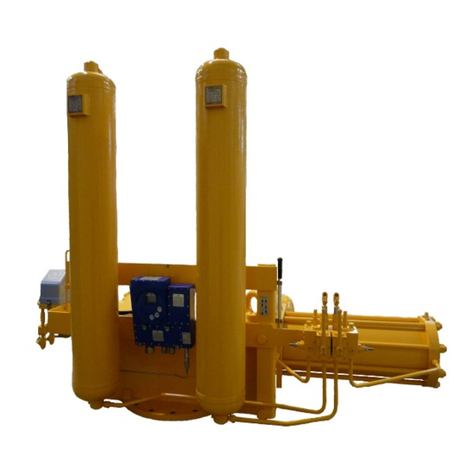
DVG ITVC Series Service manual

Intelligent Total
Valve Controller
BASIC version
Document Number
Prepared
Approved
Date
Release
IOM-ITVC
AA
GR
05/09/2017
05
INSTALLATION
SET-UP
OPERATING
& SERVICE MANUAL
ITVC Series
ITVC


ITVC Series – Intelligent Total Valve Controller IOM-ITVC-Basic-05
DVG AUTOMATION S.p.A.
Legal & Operative HQ: 29016 Cortemaggiore (Piacenza) Italy, Via G. Rossetti n° 2
Tel. (+39) 0523 255811; Fax (+39) 0523 255890;
Fully Paid In Capital: Euro 1.000.000,00= ISO 9001, ISO 14001, OHSAS 18001 CERTIFIED
REA 167410 - VAT 01494460338
COMPANY SUBJECT TO MANAGEMENT AND COORDINATION BY G.I.V.A. S.P.A. WITH HEADQUARTERS IN RHO (MILAN), RECORDED UNDER NUMBER 02917180172 IN
MILAN'S REGISTER OF COMPANIES
info@dvgautomation.it
www.dvgautomation.it SHEET 3 DI 64
DVGITVCSeries–“IntelligentTotalValve
Controller” – Basicversion
1 LEGEND.......................................................................................................................................................7
2 ITVC Intelligent Total Valve Controller .......................................................................................................7
3 Introduction................................................................................................................................................8
4 General information ...................................................................................................................................8
5 Storage........................................................................................................................................................8
6 Applicable regulations................................................................................................................................9
7 Classification and Certification ...................................................................................................................9
8 Warnings...................................................................................................................................................10
9 ITVC-features............................................................................................................................................12
9.1 Block diagram .................................................................................................................................. 12
9.2 Main characteristics ........................................................................................................................ 13
9.3 Input and Output of ITVC ................................................................................................................ 14
9.4 Status signalling............................................................................................................................... 14
9.5 BUS control...................................................................................................................................... 14
9.6 ITVC Terminal blocks ....................................................................................................................... 15
9.7 Operating principle.......................................................................................................................... 16
9.7.1 Actuator control ...................................................................................................................... 16
9.7.2 ESD Emergency Shutdown....................................................................................................... 17
9.7.3 Optional Panic Button ............................................................................................................. 18
9.7.4 Failsafe function ...................................................................................................................... 18
9.7.5 Output signalling relays ........................................................................................................... 18
9.7.6 Configurable Remote controls................................................................................................. 18
9.7.7 Interlock function .................................................................................................................... 19
9.7.8 4-20 mA analogue output........................................................................................................ 19
9.7.9 Configuration parameters protection ..................................................................................... 19
9.7.10 Display control......................................................................................................................... 19
9.7.11 Alarm, MRT Alarm, Warning.................................................................................................... 20

ITVC Series – Intelligent Total Valve Controller IOM-ITVC-Basic-05
DVG AUTOMATION S.p.A.
Legal & Operative HQ: 29016 Cortemaggiore (Piacenza) Italy, Via G. Rossetti n° 2
Tel. (+39) 0523 255811; Fax (+39) 0523 255890;
Fully Paid In Capital: Euro 1.000.000,00= ISO 9001, ISO 14001, OHSAS 18001 CERTIFIED
REA 167410 - VAT 01494460338
COMPANY SUBJECT TO MANAGEMENT AND COORDINATION BY G.I.V.A. S.P.A. WITH HEADQUARTERS IN RHO (MILAN), RECORDED UNDER NUMBER 02917180172 IN
MILAN'S REGISTER OF COMPANIES
info@dvgautomation.it
www.dvgautomation.it SHEET 4 DI 64
9.7.12 Instantaneous and Historical data and graphs........................................................................ 20
9.7.13 Test of coils of Solenoid Operated Valves ............................................................................... 21
9.7.14 Measure of closing time .......................................................................................................... 21
9.7.15 Date and time .......................................................................................................................... 21
9.7.16 Digital input repetition ............................................................................................................ 21
9.7.17 CPU’s and Diagnostics ............................................................................................................. 21
9.8 Examples of ITVC applications......................................................................................................... 22
10 ITVC HMI (ITVC Human Machine Interface) .............................................................................................24
10.1 HOME page...................................................................................................................................... 26
10.2 Actuator control mode .................................................................................................................... 27
10.3 Navigation in the MENU.................................................................................................................. 28
10.3.1 MENU chart ............................................................................................................................. 29
10.3.2 Password entry ........................................................................................................................ 30
10.3.3 Visualization of Alarms and Warnings..................................................................................... 30
10.3.4 Visualization of Pressures........................................................................................................ 31
10.3.5 LANGUAGE menu .................................................................................................................... 32
10.3.6 MEASUREMENT menu............................................................................................................. 33
10.3.6.1 Instantaneous measures sub-menu ................................................................................ 34
10.3.6.2 Historical data sub-menu................................................................................................. 36
10.3.7 SETUP menu ............................................................................................................................ 37
10.3.7.1 Set Time and Date ........................................................................................................... 39
10.3.7.2 Display Control................................................................................................................. 39
10.3.7.3 Operator menu................................................................................................................ 40
10.3.7.3.1 Change password ........................................................................................................ 40
10.3.7.3.2 Valve pos set................................................................................................................ 40
10.3.7.3.3 Firmware version......................................................................................................... 41
10.3.7.3.4 ITVC parameter............................................................................................................ 41
10.3.7.4 Administrator menu ........................................................................................................ 41
10.3.7.4.1 Change password ........................................................................................................ 42
10.3.7.4.2 Digital inputs................................................................................................................ 42

ITVC Series – Intelligent Total Valve Controller IOM-ITVC-Basic-05
DVG AUTOMATION S.p.A.
Legal & Operative HQ: 29016 Cortemaggiore (Piacenza) Italy, Via G. Rossetti n° 2
Tel. (+39) 0523 255811; Fax (+39) 0523 255890;
Fully Paid In Capital: Euro 1.000.000,00= ISO 9001, ISO 14001, OHSAS 18001 CERTIFIED
REA 167410 - VAT 01494460338
COMPANY SUBJECT TO MANAGEMENT AND COORDINATION BY G.I.V.A. S.P.A. WITH HEADQUARTERS IN RHO (MILAN), RECORDED UNDER NUMBER 02917180172 IN
MILAN'S REGISTER OF COMPANIES
info@dvgautomation.it
www.dvgautomation.it SHEET 5 DI 64
10.3.7.4.3 Output relays............................................................................................................... 43
10.3.7.4.4 Modbus 1 and Modbus 2 ............................................................................................ 43
10.3.7.4.5 Temperature limits...................................................................................................... 45
10.3.7.4.6 Service date ................................................................................................................. 45
10.3.7.4.7 Maximum stroke time ................................................................................................. 45
10.3.7.4.8 ITVC serial number ...................................................................................................... 45
10.3.7.4.9 Valve ............................................................................................................................ 45
10.3.7.4.10 Coil test...................................................................................................................... 45
10.3.7.4.11 Local and remote controls......................................................................................... 45
10.3.7.4.12 ESD shutdown............................................................................................................ 45
10.3.7.4.13 Operator menu.......................................................................................................... 45
10.3.7.4.14 MRT Maximum Repair Time...................................................................................... 45
10.3.7.4.15 Calibration L/S ........................................................................................................... 45
10.3.7.4.16 Stroke time calibration.............................................................................................. 49
10.3.7.4.17 Test coil absorption ................................................................................................... 49
10.3.7.4.18 Pressure eng unit....................................................................................................... 50
10.3.7.4.19 OP after PB action ..................................................................................................... 50
10.3.7.4.20 Panic button mode .................................................................................................... 50
10.3.7.4.21 Reset config ............................................................................................................... 50
10.3.7.4.22 Analog inputs............................................................................................................. 51
10.3.7.4.23 Out analog 1-2 calib................................................................................................... 51
11 Installation................................................................................................................................................52
11.1 Safety Recommendation ................................................................................................................. 52
11.2 Cable size ......................................................................................................................................... 53
11.3 Weights and Measurements ........................................................................................................... 53
11.4 Solenoid Operated Valves fuses ...................................................................................................... 54
11.5 Power supply ................................................................................................................................... 54
11.5.1 Power supply connection ........................................................................................................ 54
11.6 Input/output electrical characteristics............................................................................................ 55
12 Maintenance and cleaning .......................................................................................................................55

ITVC Series – Intelligent Total Valve Controller IOM-ITVC-Basic-05
DVG AUTOMATION S.p.A.
Legal & Operative HQ: 29016 Cortemaggiore (Piacenza) Italy, Via G. Rossetti n° 2
Tel. (+39) 0523 255811; Fax (+39) 0523 255890;
Fully Paid In Capital: Euro 1.000.000,00= ISO 9001, ISO 14001, OHSAS 18001 CERTIFIED
REA 167410 - VAT 01494460338
COMPANY SUBJECT TO MANAGEMENT AND COORDINATION BY G.I.V.A. S.P.A. WITH HEADQUARTERS IN RHO (MILAN), RECORDED UNDER NUMBER 02917180172 IN
MILAN'S REGISTER OF COMPANIES
info@dvgautomation.it
www.dvgautomation.it SHEET 6 DI 64
13 Troubleshooting .......................................................................................................................................56
14 Decommissioning .....................................................................................................................................59
15 Start-up procedure ...................................................................................................................................60
15.1 General checks................................................................................................................................. 60
15.2 End of travel setting ........................................................................................................................ 60
15.3 Test of absorption of coil of Solenoid Operated Valves.................................................................. 61
15.4 Test of Stroke time .......................................................................................................................... 61
15.5 Set of coil test option....................................................................................................................... 61
16 Nameplates...............................................................................................................................................61
17 Battery option...........................................................................................................................................62
17.1 Setting options in the ADMINISTRATOR menu ............................................................................... 63
WARRANTY .......................................................................................................................................................64
Trade Marks:.....................................................................................................................................................64

ITVC Series – Intelligent Total Valve Controller IOM-ITVC-Basic-05
DVG AUTOMATION S.p.A.
Legal & Operative HQ: 29016 Cortemaggiore (Piacenza) Italy, Via G. Rossetti n° 2
Tel. (+39) 0523 255811; Fax (+39) 0523 255890;
Fully Paid In Capital: Euro 1.000.000,00= ISO 9001, ISO 14001, OHSAS 18001 CERTIFIED
REA 167410 - VAT 01494460338
COMPANY SUBJECT TO MANAGEMENT AND COORDINATION BY G.I.V.A. S.P.A. WITH HEADQUARTERS IN RHO (MILAN), RECORDED UNDER NUMBER 02917180172 IN
MILAN'S REGISTER OF COMPANIES
info@dvgautomation.it
www.dvgautomation.it SHEET 7 DI 64
1 LEGEND
Protective Gloves Required
Work tools Necessary
Protective Shoes Required
Mechanical Operator
Protective Glasses Required
Operator
Prohibited to alter or remove the
nameplate
Advise
2 ITVC Intelligent Total Valve Controller
User terminal block
Actuator
terminal
block
ITVC Intelligent Total Valve Controller
HMI
Human
Machine
Interface
Cable entries
Main voltage terminals
Fuses of
Solenoid
Operated
Valves
Covers
Optional
Panic Button
ITVC
enclosure

ITVC Series – Intelligent Total Valve Controller IOM-ITVC-Basic-05
DVG AUTOMATION S.p.A.
Legal & Operative HQ: 29016 Cortemaggiore (Piacenza) Italy, Via G. Rossetti n° 2
Tel. (+39) 0523 255811; Fax (+39) 0523 255890;
Fully Paid In Capital: Euro 1.000.000,00= ISO 9001, ISO 14001, OHSAS 18001 CERTIFIED
REA 167410 - VAT 01494460338
COMPANY SUBJECT TO MANAGEMENT AND COORDINATION BY G.I.V.A. S.P.A. WITH HEADQUARTERS IN RHO (MILAN), RECORDED UNDER NUMBER 02917180172 IN
MILAN'S REGISTER OF COMPANIES
info@dvgautomation.it
www.dvgautomation.it SHEET 8 DI 64
3 Introduction
This document, IOM-ITVC-Basic, is the Installation, Operation and Maintenance manual (IOM) of ITVC,Intelligent
Total Valve Controller for pneumatic and hydraulic actuators. This manual includes only the instructions relevant to
BASIC version of ITVC. The instructions of the ITVC optional functions (PST, Line Break, HPU control module,
Modbus protocol, HIPPS, Battery, etc.) are in the documents Annex A,…,I, of the above IOM.
DVG Automation will activate only the functions requested by the user application and needed to correctly control the
actuator.
This document does not contain the instructions relevant to the actuator controlled by the ITVC. The wiring and
hydraulic diagrams present in the next pages should be considered only as examples of application of ITVC.
Refer to documentation supplied with the actuator to view the specific mechanical, electrical and hydraulic functional
diagram and instructions.
This document is an integral part of the apparatus, which must be carefully read, understood and consulted
before use and must be retained for future reference
WARNING!
Do not install, operate, or maintain an ITVC without first being fully trained and qualified in valve,
actuator and accessory installation, operation and maintenance, and carefully reading and
understanding the contents of this manual, including all safety cautions and warnings. For any
questions regarding these instructions, contact the factory before proceeding.
4 General information
DVG Automation spa products are engineered, manufactured and tested in accordance with the quality control system
complying with the international standard EN ISO 9001.
ITVC (Intelligent Total Valve Controller) is an electronic device designed to control pneumatic and hydraulic
actuators.
DVG Automation will not be responsible for any possible damage or physical injury resulting from use in other than the
designated applications or by lack of care during installation, operation, adjustment and maintenance of the machine.
Such risks lie entirely with the user. Depending on the specific working conditions, additional precautions may be
requested. Considering that DVG Automation has no direct control over particular applications, operation or
maintenance conditions, it is operator’s responsibility to comply with all applicable safety rules. Contact urgently DVG
Automation in case of dangerous situations not considered in the manual. It is total responsibility of the operator to be
according to the local health and safety regulations.
5 Storage
Receipt
On receipt of the ITVC, always check any damage. Never install a damaged unit and report the detected defect to the
forwarding agent.
Packing
Ensure that adequate protections were secured during transport.
Handling and Storage
Ensure that principal holes on enclosure are occluded with a cap.
Storage temperature: -60°C ≤ T ≤ +85°C.

ITVC Series – Intelligent Total Valve Controller IOM-ITVC-Basic-05
DVG AUTOMATION S.p.A.
Legal & Operative HQ: 29016 Cortemaggiore (Piacenza) Italy, Via G. Rossetti n° 2
Tel. (+39) 0523 255811; Fax (+39) 0523 255890;
Fully Paid In Capital: Euro 1.000.000,00= ISO 9001, ISO 14001, OHSAS 18001 CERTIFIED
REA 167410 - VAT 01494460338
COMPANY SUBJECT TO MANAGEMENT AND COORDINATION BY G.I.V.A. S.P.A. WITH HEADQUARTERS IN RHO (MILAN), RECORDED UNDER NUMBER 02917180172 IN
MILAN'S REGISTER OF COMPANIES
info@dvgautomation.it
www.dvgautomation.it SHEET 9 DI 64
6 Applicable regulations
94/9/CE: Directive on equipment and protective systems intended for use in potentially explosive atmospheres
(ATEX)
2004/108/CE EMC Directive (EMC)
EN 60079-0 Electrical apparatus for explosive gas atmospheres- Part 0: General requirements
EN 60079-1 Electrical apparatus for explosive gas atmospheres – Part 1: Flameproof enclosures "d"
EN 60079-31 Explosive atmospheres - Part 31: Equipment dust ignition protection by enclosure "t"
EN 61326-3-1 Electrical equipment for measurement, control and laboratory use. EMC requirements. Immunity
requirements for safety-related systems and for equipment intended to perform safety-related
functions (functional safety). General industrial applications
EN 61010-1 Safety requirements for electrical equipment for measurement, control, and laboratory use - Part 1:
General requirements
2006 / 95 / CE Low Voltage Directive (LVD)
EN 60529 Specification for degrees of protection provided by enclosures (IP code)
IEC 60068-2-6 Environmental testing – Part 2: Tests – Test Fc: Vibration (sinusoidal)
IEC 60068-2-27 Environmental testing - Part 2-27: Tests - Test Ea and guidance: Shock
IEC 61508 Functional safety of electrical/electronic/programmable electronic safety-related systems
7 Classification and Certification
EUM1 12 ATEX 0789 – ATEX 94/9/CE
II 2GD Ex db IIB+H2T5 Ex tb IIIC T88°C -60°C ≤ Tamb ≤ +85°C
II 2GD Ex db IIB+H2T5 Ex tb IIIC T88°C -45°C ≤ Tamb ≤ +85°C
II 2GD Ex db IIB+H2T5 Ex tb IIIC T88°C -20°C ≤ Tamb ≤ +85°C
IECEx EUT 14.0008
IP 68 – EN 60529
SIL 3 – IEC 61508
GOST – Certificate No. RU C-IT.ГБ08.B.00033
Resistance to Vibration – Certificate No. 223221TRFENV – IEC 60068-2-6
Seismic test – Certificate No. 223221TRFENV – IEC 60068-2-27

ITVC Series – Intelligent Total Valve Controller IOM-ITVC-Basic-05
DVG AUTOMATION S.p.A.
Legal & Operative HQ: 29016 Cortemaggiore (Piacenza) Italy, Via G. Rossetti n° 2
Tel. (+39) 0523 255811; Fax (+39) 0523 255890;
Fully Paid In Capital: Euro 1.000.000,00= ISO 9001, ISO 14001, OHSAS 18001 CERTIFIED
REA 167410 - VAT 01494460338
COMPANY SUBJECT TO MANAGEMENT AND COORDINATION BY G.I.V.A. S.P.A. WITH HEADQUARTERS IN RHO (MILAN), RECORDED UNDER NUMBER 02917180172 IN
MILAN'S REGISTER OF COMPANIES
info@dvgautomation.it
www.dvgautomation.it SHEET 10 DI 64
8 Warnings
WARNING!
Every notice in this manual, marked with the symbol shown to the left, concerns to the explosion risk and
must be enforced by all operators working in potentially explosive areas.
Not abiding by these rules can lead to health dangers for people and damages for things.
WARNING!
Do not open in explosive atmosphere and/or while energized. The area must be cleaned from explosive
mixture since battery and residual capacitor charge could generate electrical spark and cause explosion
WARNING!
The equipment must not be mechanically connected to a separate heat source with temperature higher than
85°C.
WARNING!
Cable glands and/or plugs must be IEC Ex certified.
WARNING!
Installation of equipment must be in accordance with IEC 60079-14 (latest edition) or national standard.
WARNING!
Earthing and protective conductors
Minimum cross-sectional area of protective conductors (IEC 60079-0 Table 10)
(S = cross sectional area of phase conductor [mm2]; SP= Minimum cross-sectional area of the corresponding
protective conductor [mm2])
S≤16; SP=S
WARNING!
External earth connection
Equipment must be securely connected to an earth ground. An earthing connection is provided externally to
the equipment. Connection must be secure so that the electrical conductors cannot be readily loosened or
twisted and contact pressure on electrical connection can be maintained in all conditions. Care must be taken
to protect the connection against corrosion.

ITVC Series – Intelligent Total Valve Controller IOM-ITVC-Basic-05
DVG AUTOMATION S.p.A.
Legal & Operative HQ: 29016 Cortemaggiore (Piacenza) Italy, Via G. Rossetti n° 2
Tel. (+39) 0523 255811; Fax (+39) 0523 255890;
Fully Paid In Capital: Euro 1.000.000,00= ISO 9001, ISO 14001, OHSAS 18001 CERTIFIED
REA 167410 - VAT 01494460338
COMPANY SUBJECT TO MANAGEMENT AND COORDINATION BY G.I.V.A. S.P.A. WITH HEADQUARTERS IN RHO (MILAN), RECORDED UNDER NUMBER 02917180172 IN
MILAN'S REGISTER OF COMPANIES
info@dvgautomation.it
www.dvgautomation.it SHEET 11 DI 64
WARNING!
Internal earth connection
Earth conductor of cables must be electrically connected to ground. An earthing connection is provided
internally to the equipment. Connection must be secure so that the electrical conductors cannot be readily
loosened or twisted and contact pressure on electrical connection can be maintained in all conditions. Care
must be taken to protect the connection against corrosion.
WARNING!
Paint procedures
No.1 (standard): 70 ÷ 100µm TGIC-free polyester powder coating
No.2 (optional): 840 ÷ 1050µm thermoplastic powder coating
WARNING!
REPAIR of equipment must be carried out according to IEC 60079-19 and only under control and
authorization of DVG AUTOMATION S.p.A. or an authorized third-party.
Nothing concerning the protection means can be modified.
Violation of the above mentioned rules will cause loss of every feature of conformity to the certificate of the
motor equipment.
WARNING!
Check periodically that maximum dust thickness on enclosure does never exceeds 5mm.
WARNING!
Perform electrical connections as per statutory requirements. In particular, check tightness and integrity of
cable glands and/or plugs. If opening of any cover is necessary, before reassembling, check integrity of
antideflagration joint/s and gasket/s, clean thoroughly and apply a small quantity of silicon grease on mating
surfaces and gasket. Tighten hex socket head screws (M6 – tightening torque 8,0 Nm).

ITVC Series – Intelligent Total Valve Controller IOM-ITVC-Basic-05
DVG AUTOMATION S.p.A.
Legal & Operative HQ: 29016 Cortemaggiore (Piacenza) Italy, Via G. Rossetti n° 2
Tel. (+39) 0523 255811; Fax (+39) 0523 255890;
Fully Paid In Capital: Euro 1.000.000,00= ISO 9001, ISO 14001, OHSAS 18001 CERTIFIED
REA 167410 - VAT 01494460338
COMPANY SUBJECT TO MANAGEMENT AND COORDINATION BY G.I.V.A. S.P.A. WITH HEADQUARTERS IN RHO (MILAN), RECORDED UNDER NUMBER 02917180172 IN
MILAN'S REGISTER OF COMPANIES
info@dvgautomation.it
www.dvgautomation.it SHEET 12 DI 64
9 ITVC-features
9.1 Block diagram
The main features of the ITVC electronic unit are:
To acquire the commands from control room
To acquire the feedback from sensors of the actuator (position pressure, etc.) and ITVC hardware (temperature,
current, etc.)
To process the acquired data and send commands to the Solenoid Operated Valves to move the process valve
To send status, alarms and warning signals of “ITVC-actuator- H/PCU” system to control room
To log alarms, warning, events
H/PCU: Hydraulic or Pneumatic Control Unit
It is made of hydraulic / pneumatic components to control the hydraulic / pneumatic power and drive the actuator in opening and closing direction (Solenoid Operated Valves,
Pneumatic and Hydraulic Operated Valves, filters, selectors, booster, flow regulated valves, etc.)
Block diagram of hydraulic or pneumatic actuator with ITVC
ITVC electronic cards
HMI card
Actuator
terminal block
Fuses of Solenoid
Operated Valves
User terminal block
Main power
terminals
Graphic LCD
display
Pushbuttons
and LED’s
Power card
Earth bar
Ferrite bead

ITVC Series – Intelligent Total Valve Controller IOM-ITVC-Basic-05
DVG AUTOMATION S.p.A.
Legal & Operative HQ: 29016 Cortemaggiore (Piacenza) Italy, Via G. Rossetti n° 2
Tel. (+39) 0523 255811; Fax (+39) 0523 255890;
Fully Paid In Capital: Euro 1.000.000,00= ISO 9001, ISO 14001, OHSAS 18001 CERTIFIED
REA 167410 - VAT 01494460338
COMPANY SUBJECT TO MANAGEMENT AND COORDINATION BY G.I.V.A. S.P.A. WITH HEADQUARTERS IN RHO (MILAN), RECORDED UNDER NUMBER 02917180172 IN
MILAN'S REGISTER OF COMPANIES
info@dvgautomation.it
www.dvgautomation.it SHEET 13 DI 64
9.2 Main characteristics
Here below are listed the most important functions of the BASIC ITVC.
Control and drive of DVG Automation pneumatic and hydraulic actuators, single acting spring return and
double acting, on-off service
Failsafe function
Redundant ESD Emergency Shut-Down function (ESD1 and ESD2 channels with diagnostic each channel)
Output to control Solenoid Operated Valves (SOV), fuse protection in each output
Test of coils of Solenoid Operated Valves (SOV)
Standard digital hardwired remote control
Interlock controls
Redundant Modbus RTU communication line
Local actuator control
Human Machine Interface (HMI) with graphic LCD display and non-intrusive, touch-sensitive, pushbuttons
Multi-language menu, icon based
User friendly navigation in the menu
Local configuration
Diagnostic functions
Two microcontrollers working in parallel with cross comparison of operations and diagnostic
Access to menu by password to protect against unauthorized change
Bluetooth wireless communication
Sensor of Temperature of Electronics
Alarm, Warning, Event logger
Real time clock and battery
SIL 3 compliance for the SIF functions (ESD Emergency Shut-Down, Line Break and Panic Button)
1oo1, 1oo2, 2oo3 and 1oo3 configuration of analogue input channels with diagnostic
Operating temperature and enclosure suitable for application in field, according to limits reported in the
Classification/Certification paragraph
Separated mounting option
Here below are listed the most important functions available and activated by DVG Automation according to the user
request
PST function (Partial Stroke Test) (see Annex A: PST function)
Line Break (LB and LB-d) function (see Annex B: Line Break function)
HPU (Hydraulic Power Unit) control module (see Annex C: HPU control module)
HIPPS (High Integrity Pressure Protection System) function (see Annex D: HIPPS function)
Panic Button (PB) (see Optional panic button paragraph)
Optional battery (see Optional battery paragraph or Annex B)
Separated mounting option: it allows mounting the ITVC separately from actuator. It is especially useful when the
actuator has to be mounted in a difficult access position, or highly vibrating valve or in excessive high/low temperature
area. The maximum length of cable between ITVC and actuator is 50m.
SIL features: the specific ITVC SIF functions “ESD Emergency shutdown”, Line Break and Panic Button comply
with IEC61508, application “Low Demand mode”. The certificate 43SO00071 is available on request.
Optional battery: if required, ITVC can be equipped (only -20°÷+85°C ITVC version) with a rechargeable lithium-ion
battery, which in case of power supply failure, keeps the ITVC functional, in monitoring mode. The battery is located
on the top of the ITVC enclosure. See Optional battery paragraph or Annex B: Line Break

ITVC Series – Intelligent Total Valve Controller IOM-ITVC-Basic-05
DVG AUTOMATION S.p.A.
Legal & Operative HQ: 29016 Cortemaggiore (Piacenza) Italy, Via G. Rossetti n° 2
Tel. (+39) 0523 255811; Fax (+39) 0523 255890;
Fully Paid In Capital: Euro 1.000.000,00= ISO 9001, ISO 14001, OHSAS 18001 CERTIFIED
REA 167410 - VAT 01494460338
COMPANY SUBJECT TO MANAGEMENT AND COORDINATION BY G.I.V.A. S.P.A. WITH HEADQUARTERS IN RHO (MILAN), RECORDED UNDER NUMBER 02917180172 IN
MILAN'S REGISTER OF COMPANIES
info@dvgautomation.it
www.dvgautomation.it SHEET 14 DI 64
9.3 Input and Output of ITVC
This paragraph lists the inputs and outputs available in the ITVC electronics. These I/O’s are collected in two terminal
blocks, one terminal block is available to user, for connection of signals with the control room, the other one is available
for connection of the actuator signals (Solenoid operated Valves, transmitters, etc.). The electrical features of the I/O’s
are described in the INSTALLATION chapter
I/O’s available on user terminal block
Digital inputs:
o2 configurable digital inputs (IN3, IN4) + Open and Close remote controls, optocoupled, 1 common.
o2 independent, separated ESD inputs (ESD1,ESD2), optocoupled,
o2 configurable digital inputs (IN1,IN2), optocoupled, 1 common
Outputs relays:
o1 Monitor relay, single side stable, SPDT contact, voltage free (Monitor Relay)
o4 configurable, latched, SPST contact, voltage free (R1,R2, R3, R4)
Analogue input:
o1 x 4-20mA channels, optocoupled isolated amplifier, factory configurable
Analogue output:
o2 x 4-20mA channels, optocoupled isolated amplifier, active and passive current loop, factory configurable
I/O’s available on the actuator terminal block
Digital inputs:
o4 digital inputs , optocoupled, 1 common, factory configurable
Digital outputs:
o8 x digital outputs , 1 common, fuse protected, to drive Solenoid Operated Valves, factory configurable
Outputs relays:
o3 x latched, SPST contact, voltage free, factory configurable
Analogue input:
o4 x 4-20mA channels, optocoupled isolated amplifier, factory configurable
9.4 Status signalling
Output status of system ITVC-H/PCU-Actuator is available:
Locally, by the HMI, Human Machine Interface, described in the chapter ITVC HMI
remotely by
o1 Monitor relay: it summarizes the Alarm and MRT alarm status
o4 latched, output relays. The condition to switch of each relay can be set by the configuration options
9.5 BUS control
2 independent RS 485, Modbus RTU communication lines, are available to control the ITVC by a Modbus
master station.

ITVC Series – Intelligent Total Valve Controller IOM-ITVC-Basic-05
DVG AUTOMATION S.p.A.
Legal & Operative HQ: 29016 Cortemaggiore (Piacenza) Italy, Via G. Rossetti n° 2
Tel. (+39) 0523 255811; Fax (+39) 0523 255890;
Fully Paid In Capital: Euro 1.000.000,00= ISO 9001, ISO 14001, OHSAS 18001 CERTIFIED
REA 167410 - VAT 01494460338
COMPANY SUBJECT TO MANAGEMENT AND COORDINATION BY G.I.V.A. S.P.A. WITH HEADQUARTERS IN RHO (MILAN), RECORDED UNDER NUMBER 02917180172 IN
MILAN'S REGISTER OF COMPANIES
info@dvgautomation.it
www.dvgautomation.it SHEET 15 DI 64
9.6 ITVC Terminal blocks
Actuator terminal block
User terminal
block
Electrical main
power supply
ITVC Intelligent Total
Valve Controller

ITVC Series – Intelligent Total Valve Controller IOM-ITVC-Basic-05
DVG AUTOMATION S.p.A.
Legal & Operative HQ: 29016 Cortemaggiore (Piacenza) Italy, Via G. Rossetti n° 2
Tel. (+39) 0523 255811; Fax (+39) 0523 255890;
Fully Paid In Capital: Euro 1.000.000,00= ISO 9001, ISO 14001, OHSAS 18001 CERTIFIED
REA 167410 - VAT 01494460338
COMPANY SUBJECT TO MANAGEMENT AND COORDINATION BY G.I.V.A. S.P.A. WITH HEADQUARTERS IN RHO (MILAN), RECORDED UNDER NUMBER 02917180172 IN
MILAN'S REGISTER OF COMPANIES
info@dvgautomation.it
www.dvgautomation.it SHEET 16 DI 64
9.7 Operating principle
9.7.1 Actuator control
The ITVC collects the commands from control room and HMI, the feedback sensors signals from H/PCU, Actuator
and Pipeline and drives the Solenoid Operated Valves of the H/PCU (Hydraulic or Pneumatic Control Unit) to open
and close the process valve by means of the single or double acting actuator. Three actuator control mode are
available: LOCAL,REMOTE and OFF. On request the OFF option can be removed.
In LOCAL, the actuator can be controlled by the local pushbuttons , and of HMI. If the display is in the
Local Command page, they work as open,close and stop actuator commands (see par. Actuator Control mode).
In REMOTE, the actuator is remotely controlled by the OPEN and CLOSE digital inputs. Further digital inputs (ESD,
PST, etc.) are available to carry out special actions (safety valve positioning, command inhibit, etc.).
In OFF no command to move the actuator is available.
Both in REMOTE and OFF the local pushbuttons , , and are available to navigate in the HMI menu. In
LOCAL they are available to menu operation only in HOME page. (see par. Actuator Control mode)
The Control Logic block handles the different source of inputs, drives the outputs, monitors the operation of the
complete system “ITVC-H/PCU-Actuator” and in case of malfunction generates Alarms,MRT Alarms, and
Warnings and carries out the configured actions. The condition of Alarm/MRT Alarm is remotely signalled by the
Monitor Relay. Four additional relay are available to signal configurable status (end of travel, warnings, etc.). ITVC
status is also locally signalled by the HMI. The minimum duration of each Local and Remote controls is 300ms
In case of “single acting spring return” actuator, when the actuator reaches the electrical end of travel (by limit switch
or analogue position transmitter), the coil of the Solenoid Operated Valve controlling the process valve is kept
energized (or de-energized). In case of “double acting” actuator, when the actuator reaches the electrical end of travel
(by limit switch or analogue position transmitter), the coil of the Solenoid Operated Valve controlling the valve is kept
energized 5 sec and then it is released.
By the ADMINISTRATOR menu, in the SETUP chapter, the following control options can be set:
Local control mode:
oPush to run: the open and close commands is active for as long as the pushbutton or is
pressed. When the pushbutton is released the action of command ends
oAuto-maintained: by pressing the or pushbutton the command open or close is activated.
Even if the pushbutton is released the command remains active. It is reset by the pushbutton or if
the actuator reaches the end of travel.
H/PCU:Hydraulic or
Pneumatic Control Unit:
made of Solenoid
Operated Valves,
hydraulic and pneumatic
valves, filter, directional
valves, etc. to drive the
Actuator in open and
close direction.

ITVC Series – Intelligent Total Valve Controller IOM-ITVC-Basic-05
DVG AUTOMATION S.p.A.
Legal & Operative HQ: 29016 Cortemaggiore (Piacenza) Italy, Via G. Rossetti n° 2
Tel. (+39) 0523 255811; Fax (+39) 0523 255890;
Fully Paid In Capital: Euro 1.000.000,00= ISO 9001, ISO 14001, OHSAS 18001 CERTIFIED
REA 167410 - VAT 01494460338
COMPANY SUBJECT TO MANAGEMENT AND COORDINATION BY G.I.V.A. S.P.A. WITH HEADQUARTERS IN RHO (MILAN), RECORDED UNDER NUMBER 02917180172 IN
MILAN'S REGISTER OF COMPANIES
info@dvgautomation.it
www.dvgautomation.it SHEET 17 DI 64
Remote control type
oDigital input: the hardwired digital signals control the actuator
oBus: the commands by Modbus control the actuator
oDigital input and Bus: digital inputs and bus can control the actuator. The Bus commands have the
priority over the digital inputs.
oFunction 2-Wires: hardwired digital control by two wires
Remote control mode:
oPush to run: the open and close commands is active for as long as the input signal is present. When
the signal disappears the action of command ends
oAuto-maintained: the command open or close is activated by the signal on the digital inputs OPEN
and CLOSE. Even if the signal is removed the command remains active. When the actuator reaches
the end of travel the command is cleared. The commands can also be cleared by a digital input if
configured as “Remote STOP”.
Remote stop:
oEnabled: the remote STOP digital signal clears both remote and local open/close commands
oDisabled: the remote STOP digital signal clears only the remote open/close commands
9.7.2 ESD Emergency Shutdown
The ESD,Emergency ShutDown, command overrides any existing command and allows the actuator executing the
emergency action to reach the safe position. The reaction time is less than 600 ms. The configuration options, in the
ADMINISTRATOR menu, allows setting:
ESD Safety position: close, open, inhibit all (stay in position)
ESD control signal polarity: ESD active when the signal is present (active HIGH or ETT:Energize-To-Trip)
or absent (active LOW or DETT:De-Energize-To-Trip)
ESD command type: push to run or self-maintained
ESD command mode: active only in REMOTE or both in LOCAL and REMOTE control mode
ESD latch: hold the ESD action until the signal is present or until a manual RESET,available in
ADMINISTRATOR menu of HMI, is entered.
ESD both active: two options are available: inactive (1oo2)and active (2oo2)
ESD signalling: While ITVC performs an ESD shutdown, it raises an alarm. This is signalled remotely, by the switch-
over of monitor relay, and locally, by the LED red colour and the icon in the Home page of display. In the
detailed alarm list appear: Performing ESD,Microprocessor 2 alarm and Safety action.
ESD Redundancy:
The ITVC has 2 independent, separated, ESD1 and ESD2, input channels and carries out the emergency action
according to the configuration options described below:
Active and signal polarity HIGH: ESD starts if the signal is HIGH in both inputs
Active and signal polarity LOW: ESD starts if the signal is LOW in both inputs
Active,any signal polarity: if the signals are different, a warning appears, no action is done, the LED
is colour fuchsia and icon is in the HOME display
Inactive and signal polarity HIGH: ESD starts if signal is HIGH at least in one input
Inactive and signal polarity LOW: ESD starts if signal is LOW at least in one input
ESD is one of the ITVC safety functions (the other ones are Panic Button and Line Break). The Diagnostics function of
the digital inputs can detect short circuit and open circuits in the ESD1/2 input channels. If the above failures occur in
2oo2 mode, the ITVC raises an “MRT timer” alarm (Fault opto ESD1 or ESD2) and switches to 1oo2 operation. When
the MRT time expires and if the alarm is still present, the ITVC performs the safe action. If the above failures occur in
1oo2 mode, the ITVC raises an alarm and performs the safe action. See “Alarm, MRT alarm and Warning”,
“Visualization of Alarms and Warnings” and “Instantaneous measures sub-menu, MRT” paragraphs.
If one only input channel is used it is mandatory to put a jumper between the terminals ESD1 and ESD2.
ETT: in the Energize-To-Trip applications the optional battery must be present.
.
A

ITVC Series – Intelligent Total Valve Controller IOM-ITVC-Basic-05
DVG AUTOMATION S.p.A.
Legal & Operative HQ: 29016 Cortemaggiore (Piacenza) Italy, Via G. Rossetti n° 2
Tel. (+39) 0523 255811; Fax (+39) 0523 255890;
Fully Paid In Capital: Euro 1.000.000,00= ISO 9001, ISO 14001, OHSAS 18001 CERTIFIED
REA 167410 - VAT 01494460338
COMPANY SUBJECT TO MANAGEMENT AND COORDINATION BY G.I.V.A. S.P.A. WITH HEADQUARTERS IN RHO (MILAN), RECORDED UNDER NUMBER 02917180172 IN
MILAN'S REGISTER OF COMPANIES
info@dvgautomation.it
www.dvgautomation.it SHEET 18 DI 64
9.7.3 Optional Panic Button
On demand, the ITVC can be equipped with an emergency Panic Button (PB) (push or pull operation can be set and the
procedure is described in the paragraph Administrator menu, SETUP chapter). When engaged, ITVC drives the valve-
actuator to its predetermined safe position. The reaction time is less than 600ms. The PB action is set by the parameter
“ESD safety position”. The PB action can be momentary or latched. In case of “latched”, the PB action can be reset by
a local command or by any local and remote command, according to the configuration of parameters “Op after PB
action” and “Panic Button mode” in the Administration menu, SETUP chapter. PB is one of the ITVC safety functions
(the other ones are ESD Emergency Shutdown and Line Break). The Diagnostics function of the digital input detects
short circuit and open circuit on the PB input channels. If the above failures occur the ITVC drives the actuator in safe
position. Option ETT (Energize-To-Trip) or DETT (De-Energize-To-Trip) are available. In case of ETT applications
the optional battery must be present.
9.7.4 Failsafe function
The Failsafe function allows the actuator performing the configured action when a Failsafe condition occurs. The
Failsafe action overrides any existing commands and works like an internally generated ESD command. It is activated
by the ITVC Diagnostics function and its action is set by the parameter “ESD safety position”. The procedure to set
the “ESD safety position” is described in the paragraph ADMINISTRATOR menu (ESD shutdown), SETUP chapter.
9.7.5 Output signalling relays
The following output contacts of relays are available to signal the status of the system “ITVC-H/PCU-Actuator” to the
user
1 Monitor relay, single side stable, voltage free SPDT contacts: it summarizes the status of Alarm and MRT
Alarm.
4 relays, configurable, latched, voltage free SPST contacts (R1, R2, R3, and R4). The action of contact and
the condition to switch are configurable. The procedure to set the relays is described in the paragraph
ADMINISTRATOR menu in the SETUP chapter.
Action of contact: the option “make” and “break” closes and opens the contact when the condition to trip occurs
Condition to trip: the table of configurable conditions to switch the R1, R2, R3, R4 relays is shown in the paragraph
ADMINISTRATOR menu, in the SETUP chapter.
9.7.6 Configurable Remote controls
The ITVC has 4 configurable digital inputs, IN1, IN2, IN3, and IN4, available on the user terminal block. Each input
can be individually associated to a control signal coming from control room. The configuration procedure is described
in the ADMINISTRATOR menu, Digital Inputs paragraph, SETUP chapter. The following options are available.
oNo set: not used
oInterlock open: input to inhibit the open command
oInterlock close: input to inhibit the close command
oPST command: input of PST command
oRemote STOP: input of STOP command
oLB action: remote command to inhibit the Line Break action once a pressure event has been detected (only if
the Valve Control is enabled). Line Break alarm is cleared.
oPressure switch: input available for an optional pressure switch or any digital signal. The signal can be
repeated on the output relays (R1,…, R4). No ITVC function is associated to the input
oAut-Man: automatic / manual
oOpen command: additional open command, it work in parallel with the OPEN digital input
oClose command: additional close commnad, it work in parallel with the CLOSE digital input

ITVC Series – Intelligent Total Valve Controller IOM-ITVC-Basic-05
DVG AUTOMATION S.p.A.
Legal & Operative HQ: 29016 Cortemaggiore (Piacenza) Italy, Via G. Rossetti n° 2
Tel. (+39) 0523 255811; Fax (+39) 0523 255890;
Fully Paid In Capital: Euro 1.000.000,00= ISO 9001, ISO 14001, OHSAS 18001 CERTIFIED
REA 167410 - VAT 01494460338
COMPANY SUBJECT TO MANAGEMENT AND COORDINATION BY G.I.V.A. S.P.A. WITH HEADQUARTERS IN RHO (MILAN), RECORDED UNDER NUMBER 02917180172 IN
MILAN'S REGISTER OF COMPANIES
info@dvgautomation.it
www.dvgautomation.it SHEET 19 DI 64
9.7.7 Interlock function
The Interlock Open and Interlock Close are two digital signals used to inhibit the opening or closing of actuator. The
function is activated by configuring 2 digital inputs, chosen from IN1,…, IN4, as Interlock Open and Interlock Close.
The Interlock digital signals come from control room or from an on-off sensor (temperature, pressure, etc.) of actuator
or pipeline. The existing open and close commands from remote digital inputs, are cleared.
The ESD command and the Failsafe function overrides the Interlock action. By the factory configuration options the
Interlock signals can be set to be active when the signal is present or absent.
9.7.8 4-20 mA analogue output
The ITVC has 2 x 4-20mA analogue outputs available on the user terminal block. Each output can be individually
associated to a different signal. The configuration of the outputs is done in FACTORY. According to the user request
and to actuator type, DVG Automation sets the signal associated to each analogue output.
The following configuration options are available:
Pressure L1 retransmission
Pressure L2 retransmission
Pressure S3 retransmission
Oil level retransmission
ITVC temperature retransmission
Valve Position retransmission
Position demand retransmission
Pressure S4 retransmission
Not used
The instructions in the paragraph ADMINISTRATOR menu, in the SETUP chapter, allows the user to re-calibrate the
output.
9.7.9 Configuration parameters protection
Unauthorised changes of parameters is prevented by 2 alphanumeric passwords, OPERATOR and ADMINISTRATOR.
One further password is reserved to DVG Automation, for factory configuration of ITVC. By the password
OPERATOR, the user can view all parameters, but can change few of them. By the password ADMINISTRATOR, the
user can view all parameters and can modify a lot of them. The ITVC shows the message “Type password” when it is
requested to change a parameter. The ITVC is supplied with the default passwords “1 0 0 0 “ (Operator) and “00001”
(Administrator) . The paragraphs ADMINISTRATOR menu and OPERATOR menu, in the SETUP menu, describe
the functions available with password OPERATOR and ADMINISTRATOR. The user can change the default
passwords by the “Change password" routine in the SETUP menu. After entering the new password, the old one
ceases to be valid, so it is important to record the password in a secure location for future retrieval. An option of the
Administrator menu, “Reset config”, allows clearing the present configuration and restoring the factory one.
9.7.10 Display control
The function sets the LCD backlight mode and the display contrast. No password is required. The function can be set in
the sub-menu with icon of the SETUP menu .
Backlight mode:
Always on: the LCD backlight is always on. The display maintains the last page (the re-power on cycle
restores the HOME page)
Automatic: the LCD backlight switches off after 2 minutes of inactivity of local pushbuttons. The display
shows the HOME page
Contrast: it can be set from 1 to 3

ITVC Series – Intelligent Total Valve Controller IOM-ITVC-Basic-05
DVG AUTOMATION S.p.A.
Legal & Operative HQ: 29016 Cortemaggiore (Piacenza) Italy, Via G. Rossetti n° 2
Tel. (+39) 0523 255811; Fax (+39) 0523 255890;
Fully Paid In Capital: Euro 1.000.000,00= ISO 9001, ISO 14001, OHSAS 18001 CERTIFIED
REA 167410 - VAT 01494460338
COMPANY SUBJECT TO MANAGEMENT AND COORDINATION BY G.I.V.A. S.P.A. WITH HEADQUARTERS IN RHO (MILAN), RECORDED UNDER NUMBER 02917180172 IN
MILAN'S REGISTER OF COMPANIES
info@dvgautomation.it
www.dvgautomation.it SHEET 20 DI 64
9.7.11 Alarm, MRT Alarm, Warning
The ITVC is provided with a powerful diagnostic program that monitors the hardware and the software execution and
generates Alarms,MRT alarm and Warning in case of malfunction. The table of the Alarms,MRT alarms and
Warnings is available in the paragraph Troubleshooting. The current Alarm / MRT alarm/ Warning can be locally
viewed by the procedure described in the paragraph “Visualization of Alarms and Warnings”
The ITVC carries out the following actions when an Alarm, MRT alarm and Warning occurs:
Warning: the ITVC does not perform any action, it only raises the local signalling of warning by the icon and by
the fuchsia LED of pushbutton . A remote signalling can be generated by the configuration options of the Output
Relays.
Alarm: the alarm condition is locally signalled by the icon and by the red LED of pushbutton , and remotely
by the tripping of the Monitor Relay. Depending on the type of malfunction the ITVC inhibits the commands to the
actuator or drives the valve in the safe position or only signals the failure.
MRT alarm: the MRT alarm condition is locally signalled by the icon and by the red LED of pushbutton ,
and remotely by the tripping of the Monitor Relay. In the list of the alarm is present “MRT timer”. The safe action due
to the malfunction is performed only when the MRT (Maximum Time to Repair) expires. Setting of MRT time is done
by the option “MRT” in the ADMINISTRATOR menu, SETUP chapter. The option “MRT”, described in the
Instantaneous measure sub-menu paragraph, MEASUREMENT menu allows viewing the type of MRT alarm and the
remaining time before than the safe action starts. This procedure allows also clearing the MRT alarm. The procedure
resets the selected MRT alarm, but it is effective only if the malfunction is solved.
If the ITVC carries out the safe action in the alarm list appear the message “Safety action” and the issue that causes it
(Performing ESD, Line break action, Panic Button, etc.).
When an Alarm/Warning ceases, the list is automatically updated. In case of Alarms and Warning present at the same
time, only the Alarms can be viewed. The Warning can be viewed only after having removed the Alarms.
The RESET function, described in the paragraph “Visualization of Alarms and Warnings”, allows clearing the
selected alarm or warning. Reset will be effective only if the issue will be solved.
The above procedure does not reset the MRT alarm. They can be cleared only by the procedure described in the
“Instantaneous measure sub-menu, MRT” paragraph, MEASUREMENT menu.
9.7.12 Instantaneous and Historical data and graphs
The ITVC acquires the variables connected to its input channels and visualizes them as: Instantaneous measures, 24
hours records, Alarm history, Temperature history, Event history. The zoom facility allows viewing the details relevant
to one hour. The procedure to view the above data is described in the “MEASUREMENT menu” of ITVC HMI
chapter.
Instantaneous measure: the values are continuously updated.
24 hours records: L1, L2, S3, S4 pressure history, Position history.
oThe records are available only if the acquisition of data was previously enabled in the SETUP menu.
oMax memory capacity: 180 days/1 sensors, 120 days/2 sensors, 60 days/3 sensors
Event History:
oThe records are available only if the acquisition of data was previously enabled in the SETUP menu.
The following events are recorded: External ESD, PSLL/PSHH (if present), (PSWLL/PSWHH=
Pressure switch low-low or high-high), PSL/PSH (if present) (PSL/PSH= Pressure level low or high),
PB(if present) (PB=Panic Button)
Temperature history: it records the minimum and maximum temperature of the Logic and Power electronic
boards
Alarm history: it records the last alarms and date (more than thousand), detected by the ITVC
PST, FST, Line Break, HPU, etc.: they are described in the ANNEX A,B,.., etc.
A
A
Other manuals for ITVC Series
1
This manual suits for next models
1
Table of contents
Other DVG Controllers manuals
Popular Controllers manuals by other brands

GARDASOFT
GARDASOFT TR-CL Series user manual

elsner elektronik
elsner elektronik KNX S2 Technical specifications and installation instructions

ISVT
ISVT IVC3100 instruction manual

Grundfos
Grundfos LC 110 Installation and operating instructions

PI
PI MS249E user manual

Danfoss
Danfoss VLT AQUA Drive FC 202 operating instructions