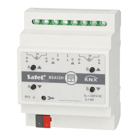
Satel KNX-BSA12L User manual

KNX-BSA12L (24 VDC)
KNX-BSA12H (230 VAC)
Blind/shutter Actuator
Firmware version 1.02 knx-bsa_en 09/20
SATEL sp. z o.o. •ul. Budowlanych 66 • 80-298 Gdańsk • POLAND
tel. +48 58 320 94 00
www.satel.eu

IMPORTANT
The device should be installed by qualified personnel.
Prior to installation, please read carefully this manual in order to avoid mistakes that can lead
to malfunction or even damage to the equipment.
Changes, modifications or repairs not authorized by the manufacturer shall void your rights
under the warranty.
SATEL aims to continually improve the quality of its products, which may result in changes in
their technical specifications and software. Current information about the changes being
introduced is available on our website.
Please visit us at:
http://www.satel.eu
The declaration of conformity may be consulted at www.satel.eu/ce
The following symbols may be used in this manual:
- note;
- caution.

SATEL KNX-BSA12L • KNX-BSA12H 1
CONTENTS
1. Features ...........................................................................................................................2
2. Description........................................................................................................................2
2.1 Enclosure ...................................................................................................................................4
2.2 Operating the module manually .................................................................................................4
2.3 Service mode .............................................................................................................................4
3. Installation ........................................................................................................................5
3.1 Wiring diagram...........................................................................................................................6
4. Configuring the module.....................................................................................................6
4.1 Function priorities.......................................................................................................................7
4.2 Configuring global parameters ...................................................................................................7
4.2.1 Weather alarms...............................................................................................................................8
4.3 Configuring channels..................................................................................................................9
4.3.1 Blind/shutter operating parameters...............................................................................................10
Motor..............................................................................................................................................17
Shutter / awning / window..............................................................................................................18
Venetian blind................................................................................................................................18
4.3.2 Functions.......................................................................................................................................20
Scene 1-bit.....................................................................................................................................20
Scene.............................................................................................................................................23
Weather alarms.............................................................................................................................25
Position forcing..............................................................................................................................26
4.4 Communication objects............................................................................................................26
4.4.1 Global objects................................................................................................................................26
4.4.2 Channel objects.............................................................................................................................29
Blind/shutter control.......................................................................................................................29
Functions.......................................................................................................................................32
4.5 Restoring module factory default settings ................................................................................34
5. Specifications .................................................................................................................34

2 KNX-BSA12L • KNX-BSA12H SATEL
The KNX-BSA12L and KNX-BSA12H are KNX blind/shutter actuators that allow you to
control the movement of sun protection products such as horizontal (Venetian) blinds, vertical
blinds, roller shutters and awnings. They also enable control of the movement of electrically-
operated windows. The KNX-BSA12L module is designed to control devices having the
24 VDC motor. The KNX-BSA12H module instead can control devices equipped with the
230 VAC motor.
The KNX-BSA12L and KNX-BSA12H modules have two physical outputs with two
corresponding logic channels. Each channel allows control of one selected type of
blind/shutter or window. Operating parameters of the channels are configured in the
ETS program in the same way for both modules, except for defining operation of the
vertical blinds, as only the KNX-BSA12L module supports this blinds.
1. Features
Communication with the KNX bus via integrated bus connector.
Feedback information about the state of module and individual channels.
Selectable type of blind/shutter for each channel.
Automatic detection of blind/shutter travel time and slat adjustment time.
Weather alarms (rain, wind, frost).
Position forcing function.
Ability to call scenes for each channel by using 1- and 8-bit commands.
Detection of blind/shutter errors (no power, incorrect position, mechanical jam, motor
overheating).
Manual control of blind/shutter travel by using buttons on the enclosure.
LEDs to indicate status of each channel / blind/shutter.
Ability to be mounted on DIN rail (35 mm).
Module configuration by using ETS program.
2. Description

SATEL KNX-BSA12L • KNX-BSA12H 3
connecting terminals for blind/shutter motors and power supply.
LEDs indicating state of blinds/shutters / channels and errors ( and –green,
–orange) –see Table 1.
LED
State of channel / blind/shutter
no blind/shutter / channel not used
blind/shutter not synchronized with module
/
/
blind/shutter travel time detection (synchronization of
blind/shutter with module)
blind/shutter fully open
position other than fully open
blind/shutter move up
blind/shutter move down
restoring module factory settings
Error type
blind/shutter error* when move up
blind/shutter error* when move down
–OFF, –ON, –flashing, / and / –LEDs are OFF and ON alternately.
* incorrect position, mechanical jam, no power / supply circuit fault, motor overheating
or obstacle detection by smart motor.
Table 1.
Blind/shutter error does not block the channel. The blind/shutter travel can be
controlled for the entire duration of the error. The error is automatically cleared when
the blind/shutter reaches the end position in the opposite direction to that in which it
was moving when the channel reported an error.
Continuous operation for too long a time or repeated activation of the blind/shutter in
very short intervals can cause motor overheating. Re-starting of the motor is only
possible after it has cooled down. The maximum continuous operation time of the
motor and the time required for cooling down after overheating are specified in the
motor manual.
buttons for manual control of blinds/shutters / channels –see Table 2.
Button
How to use
Reaction
short press
blind/shutter move one step up* / stop
long press
blind/shutter fully open
short press
blind/shutter move one step down* / stop
long press
blind/shutter fully closed
+
long press
starts process of blind/shutter travel time
detection (synchronization of blind/shutter with
module)
* function available in normal operating mode (not available in service mode).
Pressing the button is interpreted by the module as a long press, when you press and
hold down the button for longer than 1 second.
Table 2.

4 KNX-BSA12L • KNX-BSA12H SATEL
The buttons are also used for restoring the module to its factory default settings
(see “Restoring module factory default settings”).
red LED –ON during physical address assignment via the ETS program and flashes
when the service mode is active. Address assignment can be activated manually by
using the button on the enclosure or remotely from the ETS program.
programming button (used for physical address assignment). The button can also be
used to start the service mode in the module (see “Service mode”).
terminal to connect KNX bus.
2.1 Enclosure
Electronics of the KNX-BSA12L and KNX-BSA12H modules is installed in enclosures of
identical shape and dimensions. The enclosures only differ in their panels for manual control
of channel state. The figure shows enclosure dimensions based on the KNX-BSA12L
module. The module takes up 4 units on the DIN rail (35 mm).
2.2 Operating the module manually
Manual operation allows you to control the movement of blinds/shutters using the buttons
located on the module enclosure (see p. 3). The blind/shutter control is possible after
configuring the module settings in the ETS program.
The weather alarm (see “Weather alarms” p. 25) and position forcing function (see
“Position forcing” p. 26) block the manual operation of the module. The manual control
is then interrupted and the blind/shutter is set to the position defined as the reaction to
the weather alarm / position forcing function.
2.3 Service mode
The service mode allows checking whether connections between the module and the
blind/shutter motors are made properly, and whether the module correctly detects the
blind/shutter movement. You can use the service mode before configuring the module
settings in the ETS program (e.g. to set limit switches when installing the blind/shutter).

SATEL KNX-BSA12L • KNX-BSA12H 5
To enter the service mode, press and hold the button on the module enclosure for about
5 seconds. The LED next to the button will start flashing. When the service mode is started,
the blind/shutter can only be moved by using the buttons located on the enclosure (see p. 3).
Scenes and other functions will be blocked.
Table 3 contains information on operating the module in service mode.
Control
Blind/shutter
state
LED
State of connection between
module and blind/shutter
motor
long press
move up
motor connected correctly, the
module detects blind/shutter
movement
long press
move down
long press
move down
motor connected incorrectly*
long press
move up
long press
move up
motor connected correctly, but
the module detects no
blind/shutter movement**
or detects movement in one
direction only***
long press
move down
long press
no move
motor is defective / connected
incorrectly / receives no power
from the module
long press
no move
short press /
stop
–OFF, –ON
* KNX-BSA 12L –reverse the wires connecting the module with the blind/shutter motor,
KNX-BSA 12H –reverse the wires controlling the direction of motor rotation.
** Check the current consumption by the blind/shutter motor:
–if it is lower than the minimum current detected by the module, the blind/shutter travel
time must be detected manually,
–if it is higher than the minimum current detected by the module, it means failure of the
motor detection circuit in the module.
*** Take a measurement to determine the blind/shutter travel time and program it in the
module.
Table 3.
If you want to end the service mode, press and hold the button on the module enclosure
for about 5 seconds. The module will restart and the blind/shutter will be set to the position
defined by the “Reaction to KNX bus recovery” parametr. If automatic travel time detection is
programmed for the blind/shutter, the detection process will start before setting the position
(see “Travel time detection”p. 13). When manual detection is programmed for the
blind/shutter, the module assumes that the blind/shutter and slats (in the case of slat blinds)
are fully open (see “Blind/shutter operating parameters” p. 10).
3. Installation
Disconnect power before making any electrical connections.
The module is designed for indoor installation, in spaces with normal air humidity, e.g. in
distribution boxes on 35 mm DIN rail.

6 KNX-BSA12L • KNX-BSA12H SATEL
1. Mount the module on the mounting rail.
2. Connect the blind/shutter motors and power cables to the connection terminals as
indicated on the enclosure.
All connections should be made as recommended in section “Wiring diagram”.
3. Use the connection terminal to connect the KNX bus cable to the module.
4. Connect a computer running ETS program to the KNX bus and configure the module.
To configure the module, you will require a computer running the ETS program version
5.5 or newer, provided with USB or Ethernet (TCP/IP) connector. The SATEL ETS
application file, which can be downloaded from www.satel.eu/ets, must be imported
into the program.
For detailed information on how to configure the module, refer to section “Configuring the
module”.
3.1 Wiring diagram
4. Configuring the module
Working parameters of the module are defined in the ETS program (version 5.5 or higher).
The tabs for defining individual parameters are built dynamically when working with the
program. Further parameters may be displayed in the tabs or further tabs may be displayed.
Moving the cursor over the parameter will display a tooltip with default value or value range
for that parameter.
The module has two groups of configuration parameters. The first of them includes global
parameters, which define general functionality of the module and have no direct impact on
individual channels (see “Configuring global parameters”). The other group includes channel

SATEL KNX-BSA12L • KNX-BSA12H 7
parameters, which directly affect operation of the connected blind/shutter. These parameters
enable precision control of the selected blind/shutter type and make it possible to define
blind/shutter reaction to the functions activated in the module (see “Configuring channels”).
4.1 Function priorities
The position forcing function is the one having the highest priority. Priorities of the other
functions have been set as follows:
weather alarms, where priorities for individual alarms i.e. “Wind”, “Rain” and “Frost” can be
defined in the program (see “Weather alarms”),
blind/shutter position control functions.
No lower priority functions can control position of the blind/shutter until a higher priority
function is active in the channel.
Example. If the “Wind” weather alarm is triggered when the blind/shutter position control
function is active, the function will be stopped and the blind/shutter will be set to the position
defined as the reaction to weather alarm. However, if the blind/shutter position has been set
in response to the “Wind” alarm, the position control function will not be able to change the
blind/shutter position, until the alarm is called off.
4.2 Configuring global parameters
The main working parameters of the module are defined in the “Global” tab, which is
presented below.
Startup delay –time period by which the module startup will be delayed after power-on
(0 - 65535 [seconds]). Value “0”will disable the delay.
During the delay period the telegram handling is stopped and the channels do not change
their state –the blind/shutter travel is locked. The module sends no telegrams to the KNX
bus. After the delay expires, the telegrams are sent and the state of channels is set
according to the parameters defined. If any telegrams are received from communication
objects during the delay period, they will be saved. Replies to these telegrams are sent
after the delay time expires.
The startup delay may be used to reduce load on the KNX bus and supply circuit after
power-on.
Interval of cyclic device status sending –frequency with which a telegram is sent to the
bus by the “Device operation status” communication object with the module status
information (0 –65535 [seconds]). Information contained in the telegram enables the
module operation to be monitored by other devices on the KNX bus. Value “0”disables the
sending.

8 KNX-BSA12L • KNX-BSA12H SATEL
Sending telegrams may be enabled either permanently, for continuous monitoring of
the module operation, or during testing only. If you do not want to load the bus with an
excessive number of telegrams, you can set the sending cycle time at the highest
possible value.
Interval of cyclic device error (alarm) sending –frequency of sending a telegram with
information that one of the module channels is signaling a blind/shutter error. The telegram
is sent by the “Device error alarm” communication object for each type of blind/shutter
error: incorrect position, mechanical jam, no power / supply circuit fault, motor overheating
or obstacle detection by smart motor. Value 00:00:00 disables the cyclic telegram sending.
Weather alarms –enables / disables weather alarm functions in the module (Disable /
Enable). If you select “Enable”, the “Wind alarm”, “Rain alarm” and “Frost alarm”
communication objects will be activated and the “Weather alarms” tab will be available.
Channel A –the type of blind/shutter whose movement can be controlled by using the
channel A (not used / shutter / venetian blind / vertical blind / awning / window). Selecting
the type of blind/shutter will enable the communication objects to control its movement and
display the “Channel A” tab.
Channel B –the type of blind/shutter whose movement can be controlled by using the
channel B (not used / shutter / venetian blind / vertical blind / awning / window). Selecting
the type of blind/shutter will enable the communication objects to control its movement and
display the “Channel B” tab.
The “Vertical blind” type of blind is only available for the KNX-BSA12L module.
The KNX-BSA12H module does not support this type of blinds.
4.2.1 Weather alarms
Weather alarms protect the blind/shutter from damage. You can define 3 communication
objects in the module: “Wind alarm”, “Rain alarm” and “Frost alarm”. These objects can
receive telegrams sent cyclically by the (wind, rain, temperature) sensors or by the weather
station. In response to the change of state of these objects, alarms can be triggered in
the channels, as a result of which the blind/shutter travel can be stopped or the blind/shutter
can be set to a defined position. For each channel, you can define a different type of reaction
to the change of state of the communication objects linked to the weather alarms.
Position to which the blind/shutter will be set in response to a weather alarm can be
changed only as a result of a higher priority alarm (see “Weather alarms”) or by using
the position forcing function (see “Function priorities”).
For the “Wind alarm”, “Rain alarm” and “Frost alarm” objects, monitoring time can be defined.
The countdown begins when the start delay time after module power-on has elapsed.
Receiving a telegram with the value opposite to that triggering the alarm during the
monitoring time will restart the countdown (reset). If no telegram is received during the
monitoring time, the communication object will be activated.
SATEL KNX-BSA12L • KNX-BSA12H 9
Description of parameters
Wind: control scheme –value of the “Wind alarm” object activating telegram:
0 = reset monitoring time, 1 = alarm.
1 = reset monitoring time, 0 = alarm.
Wind: monitoring time –monitoring time of the “Wind alarm” object (0 – 65535 [seconds]).
With the monitoring disabled (field value “0”), the alarm will only be triggered by receiving
the “Alarm” telegram.
Rain: control scheme –value of the “Rain alarm” object activating telegram:
0 = reset monitoring time, 1 = alarm.
1 = reset monitoring time, 0 = alarm.
Rain: monitoring time –monitoring time of the “Rain alarm” object (0 - 65535 [seconds]).
With the monitoring disabled (field value “0”), the alarm will only be triggered by receiving
the “Alarm” telegram.
Frost: control scheme –value of the “Frost alarm”object activating telegram:
0 = reset monitoring time, 1 = alarm.
1 = reset monitoring time, 0 = alarm.
Frost: monitoring time –monitoring time of the “Frost alarm” object (0 – 65535 [seconds]).
With the monitoring disabled (field value “0”), the alarm will only be triggered by receiving
the “Alarm” telegram.
As good practice indicates, monitoring time of the “Wind alarm”, “Rain alarm” and
“Frost alarm” objects should be at least three times longer than the time of cyclic
telegram sending by sensors. This prevents alarm from being triggered when the
telegram resetting the monitoring time fails to be received in time because of the
excessive bus load.
Channel reaction to weather alarms can be defined in the “Weather alarms” tab.
4.3 Configuring channels
Operating parameters of blinds/shutters and their drives must be defined for each channel.
For the blinds/shutters, you should define the travel time and the slat adjustment time (for slat
blinds), and for the drives, the times that allow correction of delays occurring during operation
of the motor. For each channel, you can also define the type of blind/shutter reaction to the
functions activated in the module (weather alarms, position forcing function as well as 1- and
8-bit scenes).

10 KNX-BSA12L • KNX-BSA12H SATEL
It is recommended that the blind/shutter travel time and slat adjustment time (for all
blind types where it is applicable) be measured as a result of automatic detection done
by the module. It will make possible very accurate determination of these parameters
as well as precise control of the blind/shutter travel.
Each channel of the module has the same group of parameters. How to define the
parameters has been discussed based on the channel A.
4.3.1 Blind/shutter operating parameters
Blind/shutter travel time
Depending on whether or not the given type of blind/shutter has upper/lower limit switches,
the blind/shutter travel time may be detected by the module automatically (recommended) or
can be determined based on a measurement taken. The travel time is the time during which
the blind/shutter can be moved from one to the other end position (i.e. the position from
which the blind/shutter can only be moved to one direction). Position for all types of
blinds/shutters is defined in percentage values, where: the upper end position = 0%
(no protection –blind/shutter fully open) and the lower end position = 100% (full protection –
blind/shutter fully closed).
The figure below shows how to define the position and travel time for roller shutter and
Venetian blind.
The next figures show how to define the position and travel time for the vertical blind (Fig. 5),
awning (Fig. 6) and motorized window (Fig. 7).
The “Vertical blind” is only supported by the KNX-BSA12L module.

SATEL KNX-BSA12L • KNX-BSA12H 11
The blind/shutter travel time must be measured very carefully.
Because of their weight, the roller shutters, vertical blinds or awnings, as well as the
motorized windows, move with a different speed when traveling up or down.
For precise control of this type of blind/shutter and windows, it is recommended that
you take a measurement of the time of travel in both directions, from the upper to the
lower end position, and from the lower to the upper end position.
It is advisable to automatically detect the time of movement by the module for all
blinds/shutters that make it possible.
Slat adjustment time
This parameter applies to the slat blinds. It is the time during which the blind slats can be
adjusted from the upper to the lower end position. The position of slats is defined as
a percentage, where: 0% = the upper end position in which the slat edge located closer to the
sun can only be adjusted downwards; 100% = the lower end position in which the slat edge
located closer to the sun can only be adjusted upwards.
Fig. 8 shows how to define the slat position and adjustment time for the Venetian blind.

12 KNX-BSA12L • KNX-BSA12H SATEL
Because of their weight, the slats in Venetian blinds move with a different speed,
depending whether they are being adjusted up or down. For precise control of slat
adjustment, it is recommended that you take a measurement of the time of slat
adjustment in both directions, from the upper to the lower end position, and from the
lower to the upper end position.
Fig. 9 shows how to define the slat position and adjustment time for a vertical blind (only for
the KNX-BSA12L module).
Description of parameters
Depending on the type of blind/shutter selected for the channel “A”, different parameters are
displayed in the “A: [Blind/shutter type]” tab (where: [Blind/shutter type] = Shutter / Venetian
blind / Vertical blind / Awning / Window), visible after opening the “Channel A” tab.
During normal operation, the vertical blind motor carries out the positioning process
when turned on. The blind slats are set to one of the end positions (Fig. 9), and then to
the 50% opened position (tilting of the slats is skipped, when they are gathered

SATEL KNX-BSA12L • KNX-BSA12H 13
i.e. when the blind/shutter is fully opened –see Fig. 5). Then, the blind is moved to
one of the end positions where the slats are closed (moved to the lower end position).
The process of positioning can be interrupted at any moment by turning the motor off.
Travel time detection –you can select:
Manually on basis of measurement –blind/shutter travel time and slat adjustment time
(for slat blinds) as well as correction for delays in blind/shutter motor operation are
defined based on the taken measurements and/or data from the blind/shutter installation
guide (e.g. delays in motor operation). If you select the manual detection, fields that
allow you to enter the measured values will be displayed in the tab (see “Shutter /
awning / window” and “Venetian blind”).
If you select manual detection for a blind/shutter having limit switches, they will be
disregarded by the module and the movement will only be controlled based on the
defined time. If the blind/shutter travel is stopped by the limit switch before the time
elapses, voltage will be supplied to the motor until the defined time has elapsed.
For vertical blinds, manual detection is not available. You can only select automatic
detection for this type of blind/shutter.
Automatic after programming –the blind/shutter travel time and slat adjustment time
(for slat blinds) will be recognized and saved by the module automatically just once after
being programmed. Default value.

14 KNX-BSA12L • KNX-BSA12H SATEL
Automatic after programming and restart –the blind/shutter travel time and slat
adjustment time (for slat blinds) will be recognized and saved by the module
automatically after being programmed and after each restart.
Automatic detection is enabled only by receiving the “Move up/down” telegram or
pressing the channel control button on the module enclosure.
You can only select the automatic detection for the blind/shutter whose motor is
equipped with the upper/lower limit switch. If the blind/shutter has an electronic motor
drive, the motor quiescent current must not be higher than 25 mA for KNX-BSA L and
60 mA for KNX-BSA H.
For the horizontal blinds, the slat adjustment time cannot be recognized automatically
by the module. Therefore, the “Time of slat adjustment” parameter is also displayed
after selecting automatic detection.
If, during the automatic detection, the module detects that the blind/shutter motor is
deenergized for longer than 30 seconds, the detection process will be stopped and the
module will report lack of synchronization between the blind/shutter and the module.
If, after restarting the process (e.g. using the buttons on the module panel), the module
reports lack of synchronization, check the blind/shutter motor supply circuit for
a possible fault.
Automatic detection will not start, if the channel is locked by the position forcing
function activated in it, or the weather alarm.
Automatic detection will only be carried out properly if the module correctly detects the
movement of blind/shutter in both directions (see “Service mode”).
Position tolerance –maximum distance from the target position at which the blind/shutter
can stop –see Fig. 10 (0 –100 [%]; default= 10). If, after stopping, the distance between
the blind/shutter and the target position is greater, the channel will report an error –
incorrect position of the blind/shutter (“Channel error alarm” and “Device error alarm”
communicationn object). The blind/shutter error does not block the channel, and
blind/shutter movement control is possible for the entire duration of the error. The error will
be automatically cleared when the blind/shutter reaches the end position in the opposite
direction to the one in which it was moving when the problem occurred. After the error is
removed, a telegram is sent to the KNX bus with information that the channel is working
properly. Entering the value “0” in the field disables checking the blind/shutter position
(an incorrect blind/shutter position will not cause any error).
The “Position tolerance” parameter is only available for automatic travel time detection.
Step: object type –selects the type of data for the “Stop/step up/down” communication
object. Sets the range within which the object values can be defined:
1-bit –the object can assume value 0 or 1 (0 = step up by the value defined in the “Step:
value” field; 1 = step down by the value defined in the “Step: value” field; if the
blinds/shutters / slats are moving 0 and 1 = Stop).
4-bit –the object can assume values from 0 to 100% and value “Stop” (0% = the upper
end position (fully open); 100% = the lower end position (fully closed); Stop = movement
stopped).
Step: value –percentage value by which the blind/shutter will be moved or blind slats
adjusted in response to 1-bit telegram from the “Stop/step up/down” communication object
or by a short press of the button for manual control of channel / blind/shutter (0 –100 [%],
default value = 10). The field is displayed in the tab, if the “1-bit” data type is selected for
the object.

SATEL KNX-BSA12L • KNX-BSA12H 15
The time necessary to execute a step (blind/shutter movement / slat adjustment) must
be longer than the sum of the start delay time and the blind/shutter motor stop time.
If the step execution time is shorter than this sum, the module will be unable to
correctly control the motor operation and the step will not be executed.
Legend to Fig. 10:
X –position tolerance.
Interval of cyclic channel error (alarm) sending –frequency of sending a telegram with
information about channel error (0 –255 [seconds]). The telegram is sent by the “Channel
error alarm” communication object for each type of blind/shutter error: incorrect position,
mechanical jam, no power / supply circuit fault, motor overheating and obstacle detection
by smart motor. Value “0” disables the cyclic telegram sending.
Interval of cyclic position sending –frequency of sending a telegram with information
about current blind/shutter position (0 –255 [seconds]). The telegram is sent by the
“Current absolute position percentage” communication object. Information contained in the
telegram enables the blind/shutter position to be controlled by other devices on the KNX
bus. Value “0” disables the cyclic telegram sending.
Interval of cyclic slats position sending –frequency of sending a telegram with
information about current slat position (0 –255 [seconds]). The telegram is sent by the
“Current absolute position percentage” communication object. Information contained in
the telegram enables the blind/shutter slats to be controlled by other devices on the KNX
bus. Value “0” disables the cyclic telegram sending. The field is only displayed for the slat-
type shutters/blinds.

16 KNX-BSA12L • KNX-BSA12H SATEL
Reaction to KNX bus recovery –allows you to select the position to which the blind/shutter
will be set in response to the bus recovery (no reaction / fully opened / fully closed).
It defines the value which the “Move up/down” communication object will assume after
starting the module (0 = move up, 1 = move down).
Central move up/down –enables / disables the central function in the channel to control the
blind/shutter travel (Disable / Enable). Select “Enable” to activate the “Move up/down”
central communication object. Changing the object value will trigger a channel response,
as a result of which the blind/shutter will be moved up or down, according to the value
saved in the object.
The “Move up/down” central object allows you to move both blinds/shutters connected to
the module up or down by using one telegram.
Central absolute position –enables / disables the central function for setting the absolute
position of blind/shutter and slats in the channel (Disable / Enable). Select “Enable” to
activate the “Set absolute position percentage” / “Set absolute position slats percentage”
central communication object. Changing the object values will trigger a channel response,

SATEL KNX-BSA12L • KNX-BSA12H 17
as a result of which the blind/shutter / slats will be set to absolute positions corresponding
to the values saved in these objects.
The “Set absolute position percentage” central object sets both blinds/shutters connected
to the module to the same absolute position by using one telegram. On the other hand, the
“Set absolute position slats percentage” central object sets the slats of both blinds to the
same absolute position by using one telegram.
Central stop –enables / disables the central function for stopping the movement of
blind/shutter and slats in the channel (Disable / Enable). Select “Enable” to activate the
“Dedicated stop” central communication object. Changing the object value will trigger
a channel response, as a result of which the movement of blind/shutter or slats will be
stopped.
The “Dedicated stop” central object stops the travel of both blinds/shutters or movement of
slats in both blinds connected to the module by using one telegram.
Scene 1-bit –enables / disables the possibility of defining 1-bit scenes for the channel
(Disable / Enable). Selecting “Enable” activates the “Call scene 1-bit (1/2)” communication
object and displays the “Scene 1-bit” tab.
Scene –enables / disables the possibility of defining scenes for the channel (Disable /
Enable). Selecting “Enable”enables the “Scene”communication object and displays the
“Scene”tab.
Weather alarms –enables / disables weather alarm functions in the channel (Disable /
Enable). If you select “Enable”, the “Weather alarms”tab will be displayed. The parameter
is available, when the weather alarm functions are enabled in the module (“Weather
alarms”parameter, “Global”tab).
Position forcing –enables / disables the position forcing function in the channel (Disable /
Enable). If you select “Enable”, the “Forced position” communication object will be
activated and the “Position forcing” tab displayed.
Motor
The parameters described below are only available for manual detection of travel time.
The blind/shutter motor is characterized by some inertia, i.e. after receiving the “START”
control signal it needs time so that its rotor can reach the speed that enables the blind/shutter
travel. Also, the motor needs time so that its rotor can stop after receiving the “STOP” signal.
You must correct the delays in motor operation by entering correctly measured values in the
fields “Switch-on delay when up”, “Switch-on delay when down” and “Switch-off delay”.
Correct determination of delays in the motor operation is necessary to be able to
precisely control the blind/shutter movement. You should take into account the
technical data specified by the manufacturer of blinds/shutters in the manual.
Switch-on delay when up –time that must elapse from the moment of receiving the
“START” control signal by the motor to the moment when its rotor reaches the speed
enabling the blind/shutter to travel up (50 –16384 [milliseconds]; default = 100).
Switch-off delay –time that must elapse from the moment of receiving the “STOP” control
signal by the motor to the moment when its rotor stops (50 –16384 [milliseconds];
default = 100).

18 KNX-BSA12L • KNX-BSA12H SATEL
Switch-on delay when down –time that must elapse from the moment of receiving the
“START” control signal by the motor to the moment when its rotor reaches the speed
enabling the blind/shutter to travel down (50 –16384 [milliseconds]; default = 100).
Shutter / awning / window
The parameters described below are only available for the manual detection of travel time.
Travel time in two directions –defines how the shutter travel time will be determined:
no –based on the measurement of time of travel in one direction, e.g. from the upper to
the lower end position. Default value.
yes –based on the measurement of time of travel in two directions, from the upper to the
lower end position and from the lower to the upper end position.
Travel time –shutter travel time from one to the other end position, see Fig. 4, 6 and 7
(0 - 480000 [milliseconds]). The field is available when the “no” option is selected for the
“Travel time in two directions” parameter.
For precise determination of the shutter operating parameters, it is recommended that
measurements of travel time in two directions be taken.
Travel time up –shutter travel time from the lower to the upper end position, see Fig. 4, 6
and 7 (0 - 480000 [milliseconds]). The field is available if the “yes” option is selected for
the “Travel time in two directions” parameter.
Travel time down –shutter travel time from the upper to the lower end position, see Fig. 4, 6
and 7 (0 - 480000 [milliseconds]). The field is available if the “yes” option is selected for
the “Travel time in two directions” parameter.
Additional travel to end position –allows you to adjust the position of the blind/shutter
when moving to the end position (0 –125 [%]; default = 25). In the case of manual
detection, the blind/shutter end positions are defined in the module, based on the taken
measurements of the travel time. If the blind/shutter reaches the position stored in the
module as its end position, the module output is turned off. Entering a value greater than
“0”in the field means that after the blind/shutter reaches the end position, the module
output will remain on for the time needed to move the blind/shutter by this value. Entering
the value “0”in the field means that after the blind/shutter reaches its end position,
the module output will be turned off.
Venetian blind
The parameters described below are only available in the case of manual detection of travel
time.
This manual suits for next models
1
Table of contents
Other Satel Controllers manuals

Satel
Satel KNX-SA41 User manual

Satel
Satel INT-CR User manual

Satel
Satel ACU-220 User manual

Satel
Satel RX-2K User manual

Satel
Satel KNX-SA41 User manual

Satel
Satel RX-2K User manual

Satel
Satel ACU-270 User manual

Satel
Satel VERSA-MCU User manual

Satel
Satel ASW-100 E User manual

Satel
Satel KNX-DIM21 User manual

Satel
Satel ACU-250 User guide

Satel
Satel RX1K User manual

Satel
Satel MTX-300 User manual

Satel
Satel KNX-DIM21 User manual

Satel
Satel ABAX 2 ACU-280 User manual

Satel
Satel ACU-280 User manual

Satel
Satel Abax ACU-100 User manual

Satel
Satel ABAX 2 ACU-280 User manual

Satel
Satel MICRA VERSA-MCU User manual

Satel
Satel ABAX 2 ACU-220 User manual