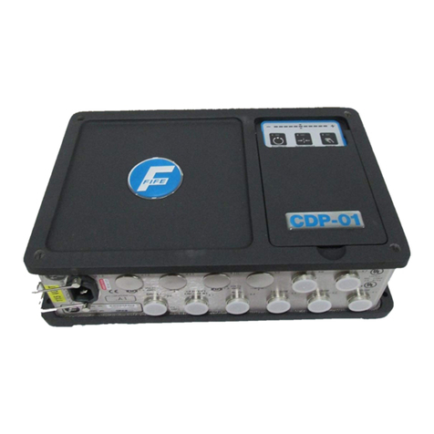
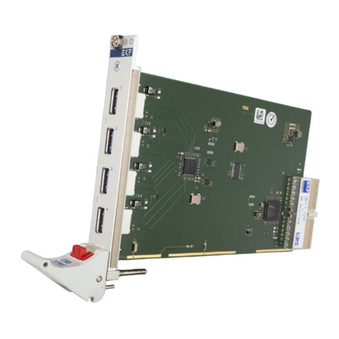
Fife CDP-01 User manual

06-26-06 CDP-01 Figure Sheet 1-878-A
© 2006 Fife Corporation. All rights reserved.
CDP-01
Additional Instruction Manual
For Side Guide Application
Using SE-34 Sensor With Width Reference
For Side Guide Width (Variable Ratio)

06-26-06 CDP-01 Figure Sheet 1-878-A
© 2006 Fife Corporation. All rights reserved.

SUPPLEMENTARY OPERATING MANUAL i
06-22-06 CDP-01 Figure Sheet 1-878-A
COPYRIGHT
NOTE
These additional instructions explain the special features of the system delivered to the customer.
They are intended for being used in conjunction with the CDP-01 Reference Manual. The CDP-01
Reference Manual applies except as noted to the contrary in these instructions.
Copyright:
All rights reserved. Any reproduction of this Additional Instruction Manual, in any form, in whole or in
part, requires the prior written consent of FIFE.
The information given in this Additional Instruction Manual is subject to change without notice.
We have compiled this Additional Instruction Manual with the greatest possible care and attention:
however, the possibility of error can not be completely excluded. FIFE accepts no legal liability for
incorrect information given and the consequences arising therefrom.
Copyright ©2006 FIFE Corporation, P.O. Box 26508, Oklahoma City, OK 73126, U.S.A.
FIFE GmbH,Postfach 1240, D-65762 Kelkheim/Ts., Germany

06-22-06 CDP-01 Figure Sheet 1-878-A

SUPPLEMENTARY OPERATING MANUAL iii
TABLE OF CONTENTS
GENERAL INTRODUCTION 1
APPLICATION DESCRIPTION............................................................................................1-1
SOFTWARE PART NUMBERS...........................................................................................1-1
CONNECTING THE SYSTEM COMPONENTS ..................................................................1-1
OVERVIEW OF FUNCTION 2
OPERATOR CONTROL OPTIONS.....................................................................................2-1
SPECIAL FEATURES OF EXTERNAL CONTROL .............................................................2-1
INPUT MATRIX - EXTERNAL CONTROL...........................................................................2-2
EXPLANATION OF THE OPERATING MODES........................................................2-3 to 2-5
START UP / GUIDE POSITION TRANSDUCER CALIBRATION........................................2-6
START UP / SIDE GUIDE POSITION TRANSDUCER CALIBRATION...............................2-7
START UP / SE-34 WIDTH CALIBRATION.........................................................................2-8
START UP / SE-34 STRIP WIDTH TO SIDE GUIDE WIDTH RATIO CALIBRATION.........2-9
START UP / SIDE GUIDE WIDTH DRIVE POLARITY......................................................2-10
START UP / GUIDE DRIVE POLARITY............................................................................2-11
TROUBLESHOOTING 3
FAULT DIAGNOSIS - FAULT RECTIFICATION........................................................3-1 to 3-2
06-22-06 CDP-01 Figure Sheet 1-878-A

06-22-06 CDP-01 Figure Sheet 1-878-A

SUPPLEMENTARY OPERATING MANUAL 1
1-1
GENERAL INTRODUCTION
Application Description
Application is a Side Guide, which uses linear analog position feedback for both the Guide and the
Side Guide width. The SE-34 width output is used for positioning the Side Guide width. The SE-34
sensor width to Side Guide width ratio is programmable. External control is required. When placed
in automatic mode, the Guide is positioned to the Sensor and the Side Guide width is positioned to
the SE-34 width. A CDP-01-MHH is required for this application.
Software Part Numbers
The software part numbers are located on the side of the CDP-01 housing. They include the Matrix
Setup no. (MS) , State Machine no. (SM) and firmware version ( Dx ).
CDP version: CDP-01-MHH D1:5650xx-02x MS: 100190.02x
D2:5650xx-02x SM: 100191.02x
D3:5650xx-02x FIFE USA
Connecting the System Components
The system components are to be connected according to the Cable Connection Diagram contained
in the documentation.
06-22-06 CDP-01 Figure Sheet 1-878-A

06-22-06 CDP-01 Figure Sheet 1-878-A

SUPPLEMENTARY OPERATING MANUAL 2
2-1
06-22-06 CDP-01 Figure Sheet 1-878-A
OVERVIEW OF FUNCTION
Operator Control Options
The CDP-01 signal amplifier can be operated by way of the CDP-01 control panel (internal operation)
for setup purposes only. For normal operational control, the parallel port must be used. Control is to
be supplied from a remote control panel or programmable logic controller.
The symbols below are used for the various operator control options in the following:
Internal operation
External operation
Special Features of External Control
When the operation modes are being controlled via
external control, the Automatic, Servo-Center, Manual
keys of the CDP-01 control panel are disabled.
If the cable to the parallel port ( -X7 ) of the CDP-01 is
disconnected, Drives 2 & 3 will Jog Right & Jog out
respectively.

SUPPLEMENTARY OPERATING MANUAL 2
2-2
06-22-06 CDP-01 Figure Sheet 1-878-A
Input Matrix - External Control
Inputs CDP-01
Modes I5 I4 I3 I2 I1 I0
Auto - - - L H H
Center - - - H L H
Manual - - - H H H
Jog Guide Right - - - - H L
Drive 2
Jog Guide Left - - - - L L
Auto L H H - - -
Center H L H - - -
Manual H H H - - -
Jog Width In - H L - - -
Drive 3
Jog Width Out - L L - - -
L = Low level
H = High level
- = any

SUPPLEMENTARY OPERATING MANUAL 2
2-3
06-22-06 CDP-01 Figure Sheet 1-878-A
Explanation of the Operating Modes
Note: All Start-up Procedures must be performed before Automatic and Servo Center
modes are used.
MANUAL
Select ‘Manual’ via external control.
The active drives are switched to Manual.
Check: LED (3) lit.
Setup functions can be performed.
‘Left’
‘Right’
Press the - or + key to set ‘Left’ or ‘Right’ to manually
alter the position of the drive.

SUPPLEMENTARY OPERATING MANUAL 2
2-4
06-22-06 CDP-01 Figure Sheet 1-878-A
AUTOMATIC – GUIDE
’Automatic’
Select ‘Automatic’ via external control for the Guide.
The Guide is switched to Automatic. The Guide now
follows the position of the strip within the sensor
bandwidth.
The guide point or system gain can be altered, if desired.
Reference: CDP-01 Reference Manual, ‘Basic Settings’
section.
AUTOMATIC – SIDE GUIDE
’Automatic’
Select ‘Automatic’ via external control for the Side Guide.
The Side Guide is switched to Automatic. The Side
Guide now follows the strip width output from the SE-34
sensor.
The guide point (distance between the Side Guide and
strip) or system gain can be altered, if desired.
Reference: CDP-01 Reference Manual, ‘Basic Settings’
section.

SUPPLEMENTARY OPERATING MANUAL 2
2-5
06-22-06 CDP-01 Figure Sheet 1-878-A
CENTER GUIDE
Select ‘Center’ for Drive 2 via external control.
The mandrel moves to the center of the stroke.
Check: LED 2 lit.
RETRACT SIDE GUIDE
Select ‘Center’ for Drive 3 via external control.
The Side Guide moves to the retract position.
Check: LED 2 lit.
JOG GUIDE LEFT / RIGHT
Select ‘Jog Guide Left’ or ‘Jog Guide Right’ via external
control to manually alter the position of the mandrel.
JOG WIDTH IN / OUT
Select ‘Jog Width In’ or ‘Jog Width Out’ via external
control to manually alter the position of the sensor.

SUPPLEMENTARY OPERATING MANUAL 2
2-6
06-22-06 CDP-01 Figure Sheet 1-878-A
Start-up / Guide Position Transducer Calibration
The following procedure must be performed while in Manual mode with all parallel inputs high.
Select Drive 2 by pressing key 20.
Press the Sensor key repeatedly until LED 11 is lit.
Press the Setup key.
Press the Sensor key.
Press and hold the Left or Right Jog key until the Guide is
located at the end of the stroke.
Press the F1 key.
Check: LED 4 lit.
Press and hold the Left or Right Jog key until the Guide is
located at the end of the stroke in the opposite direction.
Press the F2 key.
Check: LED 5 lit.
The LED bar graph indicates contrast. If the contrast
is too low an error message is displayed (left and
right outer LEDs flash).
Press the Automatic key to store the settings.
or
Press the Manual key to abort the procedure.

SUPPLEMENTARY OPERATING MANUAL 2
2-7
06-22-06 CDP-01 Figure Sheet 1-878-A
Start-up / Side Guide Position Transducer Calibration
The following procedure must be performed while in Manual mode with all parallel inputs high.
Select Drive 3 by pressing key 20.
Press the Sensor key repeatedly until LED 12 is lit.
Press the Setup key.
Press the Sensor key.
Press and hold the Left or Right Jog key until the Side
Guide is completely to its most narrow position.
Press the F1 key.
Press and hold the Left or Right Jog key to retract the
Side Guide completely to its most wide position.
Press the F2 key.
Press the Automatic key to store the settings.
or
Press the Manual key to abort the procedure.

SUPPLEMENTARY OPERATING MANUAL 2
2-8
06-22-06 CDP-01 Figure Sheet 1-878-A
Start-up / SE-34 Web Width Calibration
The following procedure must be performed while in Manual mode with all parallel inputs low.
a.
Press the Sensor key repeatedly until LED 9 is lit.
b.
Press the Setup key.
Check: LED 3 flashes.
c.
Press the Sensor key.
Check: LED 8 & 10 lit.
d.
Remove web material fully from sensor proportional
band.
e.
Press the F1 key
Check: LED 4 lit.
f.
Bring web material into sensor and fully cover the
sensor proportional band.
g.
Press the F2 key.
Check: LED 4 & 5 lit.
h.
The LED bar graph indicates contrast. If the contrast is
too low an error message is displayed (left and right
outer LEDs flash).
j.
Press the Automatic key to store the settings.
or
k.
Press the Manual key to abort the procedure.

SUPPLEMENTARY OPERATING MANUAL 2
2-9
06-22-06 CDP-01 Figure Sheet 1-878-A
Start-up / SE-34 Strip Width to Side Guide Width Ratio Calibration
Select Drive 3 by pressing key 20.
Place the MAXIMUM width of strip in the SE-34 sensor
and in the Side Guide.
Press and hold the Left or Right Jog key until the Side
Guide is just touching the strip.
Press and hold the F2 and F3 keys until LEDs 5 and 6
are lit (approximately 3 seconds).
Place the MINIMUM width of strip in the SE-34 sensor
and in the Side Guide.
Press and hold the Left or Right Jog key until the Side
Guide is just touching the strip.
Press and hold the F1 key until LEDs 4, 5, and 6 are lit.
Note: Approximately one minute is required for calculations
in this procedure. If it is desired to abort this procedure, press
and hold the Manual key until LEDs 5 and 6 turn off.
The previous calibration is retained.
Half way through the calculations (approximately 30
seconds), LEDs 4 and 6 will turn off.
Note: If it is desired to abort this procedure, press
and hold the Manual key until LED 5 turns off.
The previous calibration is retained.
When the calculations are complete (approximately 30
additional seconds), LED 5 will turn off.

SUPPLEMENTARY OPERATING MANUAL 2
2-10
06-22-06 CDP-01 Figure Sheet 1-878-A
Start-up / Side Guide Width Drive Polarity
The following procedure must be performed using External control.
Select Drive 3 by pressing key 20.
Select ‘Servo Center’ mode. Verify that the Side Guide
moves to the desired end for retract.
If the Side Guide moves the wrong direction, select
‘Manual’ and change the Servo Center polarity.
Reference: CDP-01 Reference Manual, Section “Servo
Center Polarity”.
Select ‘Automatic’ mode. Verify that the Side Guide
moves to the edge of the strip.
If the Side Guide moves the wrong direction, select
‘Manual’ and change the guide polarity.
Reference: CDP-01 Reference Manual, Section
“Changing The Guide Direction”.

SUPPLEMENTARY OPERATING MANUAL 2
2-11
06-22-06 CDP-01 Figure Sheet 1-878-A
Start-up / Guide Drive Polarity
The following procedure must be performed using External control.
Select drive 2 by pressing key 20.
Select ‘Servo Center’ mode. Verify that the Guide
moves to the center of the stroke.
If the Guide moves to either end, select ‘Manual’ and
change the Servo Center polarity.
Reference: CDP-01 Reference Manual, Section “Servo
Center Polarity”.
Place the Drive in Automatic mode. Verify that the
Guide follows the edge of the strip.
If the Guide moves to either end, select ‘Manual’ and
change the guide polarity.
Reference: CDP-01 Reference Manual, Section
“Changing The Guide Direction”.

06-22-06 CDP-01 Figure Sheet 1-878-A
Other manuals for CDP-01
9
Table of contents
Other Fife Controllers manuals
Popular Controllers manuals by other brands
Regada
Regada ST 1-Ex Installation, service and maintenance instructions
Hanna Instruments
Hanna Instruments BL 983319-0 instruction manual
ESCO Technologies
ESCO Technologies ETS-Lindgren EMControl 7006-001 user manual
Hacker
Hacker MASTER Senstrol 120A Opto manual
sauter
sauter EQJW146F001 Short manual
AOR
AOR AR-210 operating instructions
